Video-Capable Ultrasonic Wireless Communications Through Biological Tissues
←
→
Page content transcription
If your browser does not render page correctly, please read the page content below
664                     IEEE TRANSACTIONS ON ULTRASONICS, FERROELECTRICS, AND FREQUENCY CONTROL, VOL. 68, NO. 3, MARCH 2021

                    Video-Capable Ultrasonic Wireless
                        Communications Through
                           Biological Tissues
      Gizem Tabak , Member, IEEE, Sijung Yang, Rita J. Miller, Michael L. Oelze , Senior Member, IEEE,
                                 and Andrew C. Singer , Fellow, IEEE

   Abstract — The use of wireless implanted medical                        body and communicate data wirelessly to a receiver or
devices (IMDs) is growing because they facilitate moni-                    transmitter outside of the body. Because of technological
toring of patients at home and during normal activities,                   advances, these devices are rapidly becoming an integral part
reduce the discomfort of patients, and reduce the likeli-
hood of infection associated with trailing wires. Currently,               of medical diagnostic and treatment procedures. About one
radio frequency (RF) electromagnetic waves are the most                    in ten people in America and about 1 in 17 people living
commonly used method for communicating wirelessly with                     in industrialized countries rely on IMDs to regain body
IMDs. However, due to the restrictions on the available band-              function, to improve life quality or to maintain survival [1].
width and the employable power, data rates of RF-based                     Applications employing IMDs include, but are not limited to,
IMDs are limited to 267 kb/s. Considering standard def-
inition video streaming requires data rates of 1.2 Mb/s                    pacemakers that prevent cardiovascular malfunctions, insulin
and high definition requires 3 Mb/s, it is not possible to                 monitors, and pumps that control glucose levels in the blood
use the RF electromagnetic communications for high data                    and adjust insulin levels accordingly, and capsule endoscopy
rate communication applications such as video stream-                      cameras that record the digestive tract when swallowed
ing. In this work, an alternative method that utilizes ultra-              and deliver diagnostic information about gastrointestinal
sonic waves to relay information at high data rates is
introduced. An advanced quadrature amplitude modula-                       conditions. Some of these devices, such as pacemakers,
tion (QAM) modem with phase-compensating, sparse deci-                     are designed to perform a task to overcome deficiencies of
sion feedback equalizer (DFE) is tailored to realize the                   the patient’s body and to be replaced invasively once their
full potential of the ultrasonic channel through biological                batteries are exhausted. Other devices, such as ingestible
tissues. The proposed system is tested in a variety of                     cameras, are designed to be collected after data acquisition,
scenarios, including both simulations with finite impulse
response (FIR) channel models, and real physical trans-                    and the data can be processed offline. Nevertheless, these
mission experiments with ex vivo beef liver and pork chop                  systems are not connected devices that relay high-bandwidth,
samples as well as in situ rabbit abdomen. Consequently,                   real-time information. Therefore, they lack the capability
the simulations demonstrated that video-capable data rates                 of instantaneous, in situ intervention. They have to be
can be achieved with millimeter-sized transducers. Real                    followed up with invasive, interventional procedures in
physical experiments confirmed data rates of 6.7, 4.4, 4, and
3.2 Mb/s through water, ex vivo beef liver, ex vivo pork chop,             case an anomaly is detected, and a delay in necessary
and in situ rabbit abdomen, respectively.                                  clinical intervention can result in declining patient outcomes.
                                                                           Hence, a medically significant need exists to develop an
   Index Terms — Intrabody communications, quadrature
amplitude modulation (QAM) modulation, video transmis-                     active and wirelessly communicating system that can relay
sion, wireless implanted medical devices (IMDs), wireless                  information in real time or near real time to devices outside
ultrasonic communications.                                                 of the body and open up the possibility of instantaneous
                                                                           intervention.
                                                                              Currently, radio frequency (RF) electromagnetic waves are
                        I. I NTRODUCTION                                   the most frequently used method in wireless communication
                                                                           applications such as television, radio, or mobile phone com-
M        ANY     modern   wireless implanted   medical
         devices (IMDs) make use of sensors within the                     munications. When RF waves travel through the air, they
                                                                           experience little attenuation. Additionally, they can operate
  Manuscript received May 2, 2020; accepted August 26, 2020. Date          at high frequencies, where the available bandwidth is also
of publication September 1, 2020; date of current version February 24,
2021. This work was supported by the National Institutes of Health (NIH)   high. Their capability of operating at high frequencies while
under Grant R21EB025327. (Corresponding author: Gizem Tabak.)              experiencing low loss makes RF waves appropriate for long-
  The authors are with the Beckman Institute for Advanced Science          range, high data rate wireless communication applications
and Technology, University of Illinois at Urbana–Champaign, Urbana,
IL 61801 USA, and also with the Department of Electrical and Com-          through the air. However, there are various drawbacks of using
puter Engineering, University of Illinois at Urbana–Champaign, Urbana,     RF waves with wireless IMDs to transmit data through the
IL 61801 USA (e-mail: tabak2@illinois.edu).
                             .   .

                                                                           body. RF waves are highly attenuated in the body and have
  This article has supplementary downloadable material available at
https://ieeexplore.ieee.org, provided by the authors.                      limited penetration depth. RF waves can travel 10 cm through
  Digital Object Identifier 10.1109/TUFFC.2020.3020776                     the body from a deep-tissue IMD before experiencing 60 dB

This work is licensed under a Creative Commons Attribution 4.0 License. For more information, see https://creativecommons.org/licenses/by/4.0/
                                                                                                    .
TABAK et al.: VIDEO-CAPABLE ULTRASONIC WIRELESS COMMUNICATIONS THROUGH BIOLOGICAL TISSUES                                        665

of path loss [9]. In stark contrast, they can travel as far as       reasons. First, because the loss is lower compared to RF
59 m through air before undergoing the same loss at the same         electromagnetic waves, the transmission can take place at
frequency [10]. Therefore, higher power levels need to be            lower transmit power levels. As a result, the patient expe-
employed to compensate for the losses in the body due to high        riences lower, if not insignificant, tissue heating. Second,
attenuation. However, the RF signal power levels that an IMD         medical applications that utilize ultrasonic waves, such as
could deploy are limited for safety reasons, as higher power         ultrasonic imaging, have been considered as a safer option
increases the risk of tissue damage [11]. There are also federal     when compared with applications that utilize electromagnetic
regulations on the allocation of the RF spectrum use within,         waves, such as X-ray imaging, which exposes the patients to
and outside the body. The Medical Device Radio Communica-            significant amounts of ionizing radiation [17]. Third, because
tions (MedRadio) guidelines impose different rules on wireless       there are no official regulations on the ultrasonic frequency
IMDs, medical body area networks (MBANs), and medical                spectrum, the available bandwidth, and the corresponding
micropower networks (MMNs). While the first include the              potential for high data rates, are significantly higher. For all
devices designed for communicating with an implant inside            these reasons, employing ultrasonic waves for through-tissue
the body, MBAN include the network of sensors that are worn          communications at video-capable data rates offers a safe and
on the body, and MMN include implanted devices that help             efficient alternative to RF communications.
restore functions to limbs and organs. According to MedRadio            Ultrasonic waves have been used in the literature for
guidelines, the allocated operation frequencies for the IMDs         wireless in-body and through-body communications, and have
are within the range of 401–406 MHz, and the corresponding           demonstrated the feasibility of the ultrasonic communication
maximum allowed bandwidth is 300 kHz [12]. Moreover,                 link through biological tissues. A comparison of recent works
MedRadio transceivers are further limited by interference            in the literature employing ultrasound for through-tissue com-
regulations because they must be able to operate in the              munications is provided in Table I. Nevertheless, the methods
presence of primary and secondary users in those bands. Such         in the literature either achieve lower data rates (1 cm) that could not be utilized in a small
are demonstrated to be limited to 267 kb/s [13]. Considering,        implantable device [6], [8], or the communication link is
for example, the standard definition video requires 1.2-Mb/s         established through phantoms instead of real biological tissues
bitrate, while high-definition video streaming starts at 3 Mb/s      [5], [6]. To the authors’ knowledge, this work is the first work
[14], these regulations set a significant barrier against possible   to demonstrate video-capable data rates with small form factor
wireless IMD applications to include video transmission.             transducers through real ex vivo and in situ biological tissues
   For many years, ultrasonic waves have been widely used            (Fig. 1). The contributions of this work can be summarized as
as an alternative to RF electromagnetic waves in under-              follows.
water communication applications, where RF waves experi-
ence significant losses. Employing ultrasonic waves for such           1) To utilize the ultrasonic through-tissue communication
applications enables data rates of 1.2 Mb/s over 12 m under               channel more efficiently, several underwater acoustic
water [15], as opposed to 50 kb/s over similar distances with             communication techniques are tailored to this particular
electromagnetic waves [16]. Because acoustic waves have been              application. At the transmitter end, a high order, spec-
used broadly in underwater communication applications for a               trally efficient modulation technique [quadrature ampli-
long time, the characteristics of the underwater acoustic com-            tude modulation (QAM)] is utilized to relay information
munication channel have been well established. The under-                 at video-capable data rates. At the receiver end, a phase-
water acoustic communication channel is time varying due to               tracking, sparse decision feedback equalizer (DFE) [18],
motion and the changing environment, dispersive due to speed              [19] is used to compensate for the distortion and the
and attenuation values that vary with frequency, temperature,             intersymbol interference (ISI) introduced by the channel,
salinity, and pressure, frequency selective with long delay               and to recover the transmitted data successfully at high
spread due to multipath, and with Doppler effects due to                  data rates.
motion. Considering a wireless medical implant moving inside           2) Proposed communication system is tested with finite
the body and communicating with a receiving probe outside                 impulse response (FIR) channel models provided in [2].
of the body, most if not all of these characteristics apply               The simulated experiments demonstrate three to ten fold
to the through-body ultrasonic communication channel as                   increase in data rates when compared to a basic QAM
well. Hence, employing advanced underwater communication                  modem without equalization.
techniques is a promising approach to achieve video-capable            3) The system is tested in a physical test platform with
data rates through biological tissues.                                    modular transducers that have a variety of center fre-
   The similarities between the ultrasonic communication                  quencies and sizes, and are communicating through
channels through the body and under water suggest ultrasonic              different thicknesses of ex vivo beef liver slices.
waves as a promising option for high data rate transmission               The experiments demonstrate that the proposed sys-
in situ. Besides experiencing lower loss and hence propa-                 tem achieves video-capable data rates with different
gating deeper in the tissue, ultrasonic waves are desirable               transducers communicating through the real biological
for wireless through-body communications for several other                tissues.
666 IEEE TRANSACTIONS ON ULTRASONICS, FERROELECTRICS, AND FREQUENCY CONTROL, VOL. 68, NO. 3, MARCH 2021
TABLE I
C OMPARISON OF R ECENT W ORKS E MPLOYING U LTRASOUND FOR C OMMUNICATING W ITH IMD S
in [2]. Section IV expands the method to real physical experi-
ments. Finally, Section V concludes the findings of this article.
II. C OMMUNICATION S YSTEM
In the proposed communication system (Fig. 2), the digital
data stream is obtained as video data from a camera. The video
bitstream obtained from the camera is mapped into transmit
symbols by the digital modulator. The symbol sequence is
mixed with the carrier and shifted to passband. The passband
transmit signal is then realized by an arbitrary waveform
generator and transmitted through the communication channel.
The communication channel is emulated in Section III with an
FIR model, while in Section IV, the communication channel
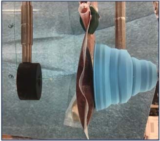
Fig. 1. This is the first work in the literature that achieves high data rates comprises the emitting transducer, the propagation medium
(>1 Mb/s) through real biological tissues (as opposed to phantoms) using (water or biological tissue), and the receiving transducer.
small form factor (
TABAK et al.: VIDEO-CAPABLE ULTRASONIC WIRELESS COMMUNICATIONS THROUGH BIOLOGICAL TISSUES 667
Fig. 2. Proposed communication system with equalizer (EQ) at the receiver.
it is more robust to Doppler [18]. At the beginning of each
data packet, a linear chirp spanning from −( f b /2) to ( f b /2)
followed by a guard interval is appended. The guard interval is
included to prevent the spreading of the preamble into the data
packet due to long channel impulse response. The transmission
packet, which consists of the linear chirp preamble, guard
interval, and data packet, is then mixed with a sinusoidal
carrier, where f c is the center frequency of the transmission
band. The passband signal
N−1
x(t) = Re x k p(t − kTb )e j 2π f c t
(2)
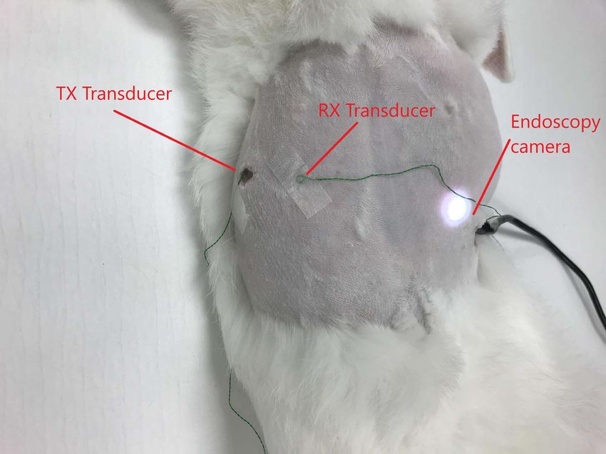
Fig. 3. Transmitting and receiving transducers with different center
frequencies and form factors, with inch rulers for reference. k=0
is then sent through the channel.
The data rate in a digital communication system is given
B. Communication Channel
by
The communication channel consists of the transmit-
R = f b log2 M ting transducer, the transmission medium, and the receiving
transducer.
where fb is the symbol rate and log2 M represents the
1) Transducers: The physical characteristics of transducers
number of bits in a symbol. fb is limited by the bandwidth
affect the data rates and the capability of the application in dif-
of the communication channel. Hence, to achieve high data
ferent ways. In a practical deployment scenario, the transducer
rates, the available bandwidth should be utilized as efficiently
is limited due to size constraints and the need to be biocompat-
as possible with a high-order modulation technique that can
ible. Furthermore, the directivity of the source affects the SNR
represent as many bits with one symbol as possible.
of the received signal, and the center frequency is related to the
In this article, QAM is used due to its potential for
level of attenuation of the signal and the available bandwidth.
high spectral efficiency. The modulator maps the binary data
obtained from the webcam into N symbols {x 1 , . . . , x N } ∈ 1) Directivity: An essential property of a transducer is
{0, . . . , M − 1}, which corresponds to N log2 M bits. M its ability to focus the transmitted energy in a par-
represents the order of QAM and indicates the number of ticular direction and its sensitivity to the direction of
possible complex symbol values the transmitted symbols may the received signal. The more directional a transducer,
take. The symbols are upsampled by L = ( f s / f b ), where f s the higher the projected and received signal power,
is the sampling frequency of the digital-to-analog converter in resulting in higher SNR at the focal point. However,
the arbitrary signal generator, and shaped with a root-raised increased directivity requires the transmitting and receiv-
cosine filter p(t), resulting in the data packet ing transducers’ fields to be aligned precisely, or else
the received signal might degrade significantly. Beam
N−1
spread of highly directive transducers also causes sub-
x D (t) = x k p(t − kTb ) (1) stantial changes in the received signal depending on the
k=0
transmitter and receiver alignment.
where Tb = (1/ f b ) is the symbol period. 2) Center Frequency: The center frequency of a transducer,
To detect the signal arrival at the receiver, a preamble is which dictates the frequency band of the passband
appended at the beginning of each data packet at the transmit- signal, impacts the attenuation of the signal through a
ter, and the preamble is matched filtered at the receiver. This medium. In soft tissue at clinical ultrasonic frequen-
synchronizing preamble can be a chirp signal, or it can be cies, the attenuation increases with frequency. Therefore,
a signal waveform representing a set of symbols. In this higher frequencies give rise to lower signal power levels
application, linear chirp is chosen as the preamble because over the same transmission distance (Table II). On the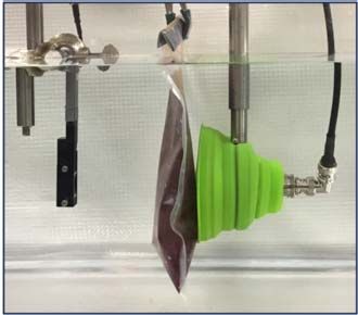
668                          IEEE TRANSACTIONS ON ULTRASONICS, FERROELECTRICS, AND FREQUENCY CONTROL, VOL. 68, NO. 3, MARCH 2021

                           TABLE II
 ATTENUATION OF U LTRASONIC WAVES AT D IFFERENT F REQUENCIES
                 FOR D IFFERENT T ISSUES [20]

     other hand, higher center frequency usually results in
     higher available bandwidth, which enables higher data
                                                                    Fig. 4. Without equalization (green stars), received symbols cannot be
     rates. As an example, consider a transmission signal with      recovered successfully at higher data rates due to spreading effects of
     30-dB SNR at 5 cm distance in fat tissue, and assume           the channel on the transmitted symbols. The equalizer compensates for
     the channel is flat within K % of the center frequency.        most of the channel effects and the received symbols after the equalizer
                                                                    (orange squares) are better distinguishable. The symbols at output of
     Losses due to absorption would limit the modulation            the equalizer are comparable to the ones received through an AWGN
     to 1024-QAM at 1 MHz, and to 64-QAM at 5 MHz,                  channel (blue diamonds).
     yielding data rates of 0.1 K Mb/s and 0.3 K Mb/s,
     respectively, for example, for K = 10, this corresponds
     to 1 Mb/s at 1 MHz and 3 Mb/s at 5 MHz. At 9 cm, same          of symbols, causing ISI. Due to ISI, the transmitted symbols
     input signal would allow for 1024-QAM at 1 MHz and             spread into each other at high data rates, and they are no longer
     QPSK at 5 MHz, both yielding data rates of 0.1 K Mb/s.         distinguishable as separate pulses at the receiver.
     On the other hand, the absorption at frequencies above
     9.2 MHz at 5 cm and above 5.4 MHz at 9 cm would                C. Channel Equalization
     prevent QAM communication altogether. These rough
                                                                       The transducers and the transmission medium impose limits
     estimates, although dependent on various hypothetical
                                                                    on the frequency components of the signal waveform that can
     assumptions such as a flat channel response, demon-
                                                                    pass through the channel. To achieve sufficient data rates for
     strate the intricacies of the trade-off between attenuation,
                                                                    video streaming through bandlimited communication channels,
     penetration depth, and data rate, and emphasize the
                                                                    higher order modulation needs to be employed. However,
     importance of choosing an appropriate center frequency.
                                                                    because of dispersion, ISI, phase and frequency distortion, and
  3) Size: The constraints imposed by the application typ-
                                                                    noise, it is not possible to retrieve the higher order transmitted
     ically limit the size of the transducer. For example,
                                                                    QAM symbols at the receiver. Moreover, due to the long
     transducers that could be used in a wireless capsule
                                                                    impulse response of the channel, without further processing,
     endoscopy pill device would need to be smaller than
                                                                    ISI becomes a further limiting factor in the data rates of the
     the pill, which typically measures at 1.1 cm × 2.6 cm
                                                                    transmission system. Without equalization, received symbols
     [21], whereas the size of a permanently implanted device
                                                                    cannot be demodulated successfully at higher data rates due
     might range from less than 1 mm3 to a few cm3 [22].
                                                                    to degrading effects of the channel on the transmitted signal
   2) Transmission Medium: The tissue type and the different        (Fig. 4). The equalizer aims to compensate these effects of the
segments that constitute the tissue affect the attenuation of the   channel to achieve better BER.
signal. To explore the effects of the transmission channel on          There are different ways to mitigate ISI, including designing
the data rates, experiments were conducted through different        longer symbol durations, introducing guard intervals between
media such as water, ex vivo beef liver, ex vivo pork chop,         symbols or designing a robust receiver that can compensate
and in situ through a rabbit abdominal wall. Beef liver and         for the nonideal channel effects. The first two options would
pork chop samples were initially used for this study because        reduce the symbol rate, and hence the data rate. Therefore,
they are easy to obtain (e.g., can be bought from a grocery         in this work, it is most convenient to use a robust receiver
store). Furthermore, beef liver is a representative example         that can compensate these effects of the channel and achieve
of a homogeneous biological tissue while the pork chop is           better BER performance at higher data rates.
a nonhomogeneous tissue consisting of layers with different            For a known channel with ISI, the optimum receiver (that
attenuation and scattering properties.                              minimizes sequence error probability) is a matched filter fol-
   Through water and the biological tissues used in this            lowed by a maximum likelihood sequence detector (MLSD).
study, different frequencies travel with small variations in        One disadvantage of MLSD is its complexity, which grows
speed. More importantly, they are attenuated at different rates.    exponentially with the channel impulse response length. This
In addition, the layers and the inhomogeneities within the tis-     makes MLSD an almost intractable solution for channels with
sues, as well as their reflective surroundings, cause multipath.    relatively long delay spread. A commonly used alternative for
As a result, the channel impulse response spans some number         equalization is the DFE [23], which consists of two parts:
TABAK et al.: VIDEO-CAPABLE ULTRASONIC WIRELESS COMMUNICATIONS THROUGH BIOLOGICAL TISSUES 669
a feedforward filter and a feedback filter. The feedforward filter TABLE III
operates on the received signal, and the feedback filter operates H IGHEST ACHIEVED D ATA R ATES R W ITH BER < 1 E -4 FOR
S IMULATED E XPERIMENTS W ITH 80-mm FIR C HANNEL M ODELS
on the past symbol decisions. The operation of the feedforward
filter cancels out the noncausal ISI, and the feedback filter
removes causal ISI by feeding back previous symbol decisions,
which are assumed to be known. When the channel impulse
response is not known, the filters can be updated using a
training sequence and an adaptive gradient descent [e.g., least
mean squares (LMS)] or least squares [e.g., recursive least
squares (RLS)] algorithm to update the filters.
A QAM signal requires coherent detection of the signal
at the receiver for successful equalization and demodulation.
Hence, a preamble is used to coarsely align the received
signal. To obtain a reasonable coarse alignment that would
fall within a few samples of the precise alignment, a preamble mimicking implant to implant communication inside the body
which has a high peak-to-sidelobe ratio in its autocorrela- (I2I-Bone); 4) gelatin phantom with transducers placed on
tion function should be chosen. Furthermore, by choosing the surface of the phantom, mimicking implant to implant
an appropriate preamble, a coarse Doppler estimate can be communication on the surface of the body (S2S-Gelatin);
obtained, enabling the resampling of the signal at the receiver and 5) gelatin-bone phantom with transducers placed on
before demodulation and equalization. A linear chirp provides the surface of the phantom, mimicking implant to implant
high peak-to-sidelobe ratio and it can also be used for coarse communication on the surface of the body (S2S-Bone).
Doppler estimation [18]. After coarse alignment and Doppler
correction, the remaining Doppler effects and variations during A. Setup
the transmission can be compensated using a phase-locked
loop, which enables the receiver to adapt to the slow phase The communication system in Fig. 2 is simulated by
fluctuations, in combination with a fractionally spaced DFE replacing the transducers and the propagation medium with
that uses more than one received signal sample for each the provided channel models for 80-mm propagation dis-
symbol (i.e., filter taps are located at fractions of a symbol tance. The transducers used in [2] are the same biocom-
period) to account for symbol timing drifts [18]. Once the patible 2-mm sonomicrometry crystals in this work. For
transmitted symbols are estimated by the equalizer, they are each channel model, 16 experiments are repeated 100 times
mapped back to the bitstream and the corresponding video for each M-QAM, M ∈ 2{2,4,6,8} , and symbol rate
data. f b ∈ {100, 250, 500, 625} kHz. The transmit data consisted
A reverberant channel with a long impulse response may of 50 000 random bits. The bits mapped into corresponding
require a long feedback filter to compensate for the channel. QAM symbols and modulated on the carrier signal centered
Such equalizers may prohibit implementation in practical sce- at fc = 1.2 MHz. The modulated waveform was preceded with
narios with limited computational resources and require exces- a 10-μs linear chirp and 1-ms guard interval. The simulated
sive training data [19]. When the channel impulse response received signals are obtained by adding white Gaussian noise
is long but sparse, a workaround would be placing zeros with variance that corresponds to the desired SNR, measured
within the span of the feedback filter where the response does per bit, represented as E b /No . The received signal is first
not contain significant arrivals. For the DFE proposed in this matched-filtered with the linear chirp to synchronize the signal
work, locations of the significant arrivals are determined with arrival time, then fed into fractionally spaced DFE, which had
matched filtering with the linear chirp in the guard interval, 18 1/2-spaced feedforward taps and 100 feedback taps. About
and setting the feedback filter taps to zero when the matched 10% of the symbols are used for training, and DFE taps are
filter output is below the threshold τ = 3(RC (0)σG2 )1/2 , where updated with the RLS algorithm with learning rate 0.997.
σG2 is the noise variance estimated from the guard interval and
RC (τ ) is the chirp autocorrelation function. B. Results
An experiment performed with an (M, fb ) pair was consid-
III. FIR C HANNEL S IMULATIONS ered successful if it could reach BER < 1e-4 for E b /No <
To determine the theoretical limits of the QAM modem 30 dB. For each channel type, successful experiments that
and to compare the high data rate capabilities of the pro- resulted in the highest data rates by utilizing the proposed
posed method and the methods in the literature, a series of method are summarized in Table III. For each success-
simulated experiments were performed with the FIR channel ful experiment, BER versus E b /No curves in Fig. 5 were
measurements provided in [2]. The channel measurement obtained by averaging the BER over 100 trials. For each trial,
data set includes impulse response models of five different the received signal was also demodulated without equalization,
types of ultrasonic communication channels through: 1) water; which yields the results obtained with the basic QAM modem
2) gelatin phantom with embedded transducers, mimicking (QAM modulation and demodulation without equalization) in
implant to implant communication inside the body (I2I- [2]. To establish the baseline for the AWGN channel, demod-
Gelatin); 3) gelatin-bone phantom with embedded transducers, ulation was performed on the noisy signal without channel670 IEEE TRANSACTIONS ON ULTRASONICS, FERROELECTRICS, AND FREQUENCY CONTROL, VOL. 68, NO. 3, MARCH 2021
Fig. 5. BER versus Eb /No plots of successful experiments that achieve the highest data rates using DFE for five different 80-mm channel models (blue
solid line), compared with decoding without equalization (red dashed line) and AWGN channel (black dottedline). (a) Water (16-QAM, 625 kSymps).
(b) I2I - Bone (16-QAM, 625 kSymps). (c) I2I - Gelatin (16-QAM, 500 kSymps). (d) S2S - Bone (QPSK, 100 kSymps). (e) S2S - Gelatin (QPSK,
100 kSymps).
to achieve better communication performance through water
when compared to other channels in the given setup because
there is less absorption and reverberation. However, the per-
formance for the 80-mm water channel in these experiments is
slightly worse than 80-mm I2I-Bone channel. This is likely due
to time variations in the 80-mm water channel measurements.
In accordance with the findings in the literature, the simula-
tions demonstrated that the basic QAM modem is not capable
of communicating at high data rates required for video trans-
mission through biological tissues with small, biocompatible
transducers for given channel models. An advanced equalizer
tailored for this particular application, on the other hand,
shows promise toward the video-capable data rates through
biological tissues at moderate to high SNR levels.
Fig. 6. With the proposed DFE modem (DFE), 1 Mb/s (QPSK,
500 kSymps) is achieved with BER of 1e-4 at 13 dB. The same IV. E XPERIMENTS
communication parameters result in BER > 2e-2 with basic QAM modem
(without EQ) at 13 dB. To test the capabilities of the proposed method on real
data, two sets of experiments were performed on ex vivo
and in situ biological tissues. In the first set of experiments,
effects. Without equalization, the channel frequency response different transducers were used to communicate through water
needs to be fairly flat for successful communication with basic and different thicknesses of ex vivo beef liver to explore the
QAM modem to prevent interference between transmitted capabilities of the method with transducers that have different
symbols. The channels with 2-mm transducers in [2] have a bandwidths and received signal powers through similar type
−3-dB bandwidth less than 180 kHz, which only allowed for of transmission media. In the second set of experiments,
successful communication at 400 kb/s through water, 200 kb/s small, biocompatible transducers were used through ex vivo
through implant-to-implant channels and did not allow for pork chop and in situ through the rabbit abdomen to explore
successful communication with the given parameters through the capabilities of the method through different media and
surface-to-surface channels without equalization. As listed in surrounding environments.
Table III, equalization enabled wider bandwidth by compen-
sating for nonflat channel frequency response. As a result,
the proposed method achieved at least 2 Mb/s, providing more A. Different Transducers, Similar Channels
than five times increase in the data rates through water and 1) Setup: The first set of experiments were performed in
ten times increase through implant-to-implant communication a water tank filled with degassed water. In the water tank,
channels when compared to the basic QAM modem. More- two transducers were placed in a pitch-catch configuration.
over, it enabled communication at 200 kb/s through surface-to- In the through-water experiments, the plastic bag, in which
surface channels, which was not possible without equalization. the beef liver was placed in further experiments, was filled
The required SNR for 200 kb/s through implant-to-implant with degassed water and suspended between the transducers
channels with a basic QAM modem is reported as 13 dB in to account for the reflective properties of the bag. In the
[2]. Although SNR values required to achieve the data rates in experiments with beef liver, ex vivo beef livers of different
Table III are higher than 13 dB, the proposed method achieved thicknesses placed in between the transducers (Fig. 7). The
1 Mb/s through water and implant-to-implant channels at experiments were conducted using four different transducers
13 dB (Fig. 6). Under normal circumstances, one would expect (Fig. 3) that have different sizes, directivities, and centerTABAK et al.: VIDEO-CAPABLE ULTRASONIC WIRELESS COMMUNICATIONS THROUGH BIOLOGICAL TISSUES 671
TABLE IV
E XPERIMENTAL T RANSMISSION PARAMETERS , R ESULTING D ATA R ATES W ITH BER < 1 E -4 AND SNR AT THE O UTPUT OF THE E QUALIZER FOR
T RANSMISSIONS T HROUGH D IFFERENT M EDIA W ITH D IFFERENT T RANSDUCERS
at the receiving transducer via potential signal paths reflected
from the tank’s walls without traveling through the biological
tissue. A direct channel was also established by connecting the
signal generator to the second channel of the digitizer with
a BNC cable. The delay between direct and acoustic signal
arrivals corresponded to the distance between transmitting
and receiving transducers, hence demonstrating successful
electrical isolation and ensuring acoustic path integrity.
The transmission data were generated from random bits
with different symbol rates and modulation orders as described
in Section III-A. For each experiment setup, two packets
of 20 000 symbols each were generated randomly with chirp
and guard interval preceding each packet. In all the exper-
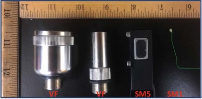
Fig. 7. Experimental setup with different transducers suspended in a
water tank, facing each other with beef liver in between. A silicone funnel iments, the signal was generated, transmitted, recorded, and
was used to prevent potential paths reflecting from the tank’s walls and then processed. An arbitrary waveform generator (PXI-5422,
arriving at the receiver without passing through the tissue. (a) 2 mm at National Instruments, Austin, TX, USA) was used to generate
1.3-MHz transducer (SM1) through 2-cm beef liver. (b) 5 × 8 mm2 at
5-MHz transducer (SM5) through 2-cm beef liver. the transmission signal at the preset center frequencies with
different bandwidths, and coded with different modulation
schemes. A digitizer was used (PXI-5124, National Instru-
frequencies to examine the effects of each of these factors on ments, Austin, TX, USA) to acquire the signal at the receiver
data rates. The transducers used in the experiments were: large, end. To drive the National Instruments equipment and to
focused, and directional transducers with 1- and 5-MHz center process the received data, custom MATLAB (MathWorks,
frequencies (IL0106HR and IL0506HR, Valpey Fisher, Hop- Natick, MA, USA) software was used.
kinton, MA, USA), denoted as VF1 and VF5, biocompatible At the receiver end, the signal was captured by the digitizer,
sonomicrometry crystals of 2-mm diameter that operate around coarsely aligned and corrected for Doppler effects using the
1.2 MHz (2-mm Round, Sonometrics, London, CAN), denoted chirp preamble, and the received data packet was decoded
as SM1, and a single-element, 5 mm × 8 mm rectangular using the fractionally spaced, phase-tracking, sparse DFE [18],
transducer at 5 MHz (E1423, Valpey Fisher, Hopkinton, MA, [19]. The equalizer had at most 53 feedforward taps and
USA) denoted as SM5. At the receiver end, because the 90 feedback taps. Out of 20 000 symbols transmitted in each
applications are typically not limited by the transducer size packet, 10% were used for training except through water with
outside of the body, large and highly focused transducers with VF5 to learn the equalizer coefficients, and the rest were used
1- and 5-MHz center frequencies, VF1 and VF5, were used to in the decision-directed mode while updating the equalizer
maximize the received signal power. The receiving transducer coefficients to track the channel variations. The signal power
was also placed inside a soft, silicone funnel that would act was higher with the focused transducers, and attenuation of
as an acoustic damper to verify that the signal does not arrive the signal when communicating through water was less than672 IEEE TRANSACTIONS ON ULTRASONICS, FERROELECTRICS, AND FREQUENCY CONTROL, VOL. 68, NO. 3, MARCH 2021
Fig. 8. Transmission of the data, obtained with an endoscopy camera,
through the abdominal wall of a rabbit using 2-mm sonomicrometry
crystals.
TABLE V
D ATA R ATES W ITH C ORRESPONDING BERs T HROUGH D IFFERENT
T ISSUES U SING 2-mm SM1 T RANSDUCERS
Fig. 9. Mean-squared error (left) and received signal constellation after
equalization (right) for transmissions through 2-cm ex vivo pork chop
(top), 8-cm ex vivo pork chop (middle), and in situ rabbit abdomen
(bottom).
with 2-mm transducers (SM1) communicating through ex vivo
pork chop and in situ through the rabbit abdomen. First,
two SM1 transducers were attached at each sides of 2- and
8-cm pork chops suspended in air. The transmission data
were obtained from a webcam (c925e USB HD Webcam,
Logitech, Lausanne, Switzerland) that has onboard h.264 video
compression. Through 2- and 8-cm pork chops, 16-QAM,
through biological tissues. These resulted in longer channel 1.4-MHz center frequency signal with 500-kHz symbol rate
impulse responses through water with VF1, for which a 14% and 16-QAM, 1.4-MHz center frequency signal with 400-kHz
training was required for the feedback filter to cover the causal symbol rate were transmitted, respectively.
channel response. The coefficients were updated using the RLS The experiments were repeated by streaming video with
algorithm with learning rate 0.997. SM1 transducers through the abdominal wall of a eutha-
2) Results: The results of the first set of transmission exper- nized rabbit to demonstrate in situ transmission capabilities
iments through water and beef liver are listed in Table IV. of the system. The transmitting transducer was implanted
The thickness of the biological tissue increased attenuation, behind the abdominal wall, and the receiving transducer
and resulted in decreased data rates for a given transmission was placed on the shaved abdomen of the rabbit with gel
frequency. For a given thickness, higher frequencies provided coupling (Fig. 8). The distance between the two transducers
higher data rates despite the increased attenuation, thanks to was 2.2 cm. The data were obtained through an endoscopy
higher available bandwidth. However, the form factors of the camera (T01 8.5-mm USB Semi-Rigid Endoscope, Depstech)
high-frequency transducers are too large to be used in an placed inside the abdomen of the rabbit. The data were
IMD such as video capsule endoscopy pill. Hence, it is more sent through the rabbit abdomen with a 256-QAM, 1.1-MHz
realistic to focus on the small form factor transducers (SM1), center frequency signal with 400-kHz symbol rate. A sim-
for which the experiments demonstrated video-capable data ilar receiver structure to Section IV-A was used for each
rates through water and beef liver. experiment.
2) Results: The mean-squared error plots and constellation
diagrams for received, equalized symbols sent through the
B. Different Channels, 2-mm Transducers pork chops are displayed in the top and middle plots of Fig. 9.
1) Setup: To examine the effects of tissue properties on The results demonstrate successful demodulation of the sym-
the data rates, the second set of experiments were performed bols for each experiment. Although the current experimentalTABAK et al.: VIDEO-CAPABLE ULTRASONIC WIRELESS COMMUNICATIONS THROUGH BIOLOGICAL TISSUES 673
results achieved video-capable data rates of 2 and 1.6 Mb/s [3] M. L. Wang and A. Arbabian, “Exploiting spatial degrees of
with BER < 6.25e-5, the E b /No at the output of the equalizers freedom for high data rate ultrasound communication with
implantable devices,” Appl. Phys. Lett., vol. 111, no. 13, Sep. 2017,
in these experiments suggest that successful demodulation Art. no. 133503.
would be possible with even higher order of QAM. Specifi- [4] T. C. Chang, M. L. Wang, J. Charthad, M. J. Weber, and A. Arbabian,
cally, 28-dB output E b /No for the 2-cm pork chop experiment “A 30.5 mm3 fully packaged implantable device with duplex ultrasonic
data and power links achieving 95kb/s with674 IEEE TRANSACTIONS ON ULTRASONICS, FERROELECTRICS, AND FREQUENCY CONTROL, VOL. 68, NO. 3, MARCH 2021
Gizem Tabak (Member, IEEE) received the B.S. Michael L. Oelze (Senior Member, IEEE) was
degree in electrical engineering from Bilkent born in Hamilton, New Zealand, in 1971.
University, Ankara, Turkey, in 2014, and the He received the B.S. degree in physics and math-
M.S. degree in electrical and computer engi- ematics from Harding University, Searcy, AR,
neering from the University of Illinois at Urbana– USA, in 1994, and the Ph.D. degree in physics
Champaign, Urbana, IL, USA, in 2016, where she from the University of Mississippi, Oxford, MS,
is currently pursuing the Ph.D. degree. USA.
She was a Fulbright Scholar during her M.S. From 2000 to 2002, he was a Postdoctoral
studies, and a Motorola Solutions Foundations Researcher with Bioacoustics Research Lab-
Scholar during the academic year 2019. Her oratory, Department of Electrical and Com-
research interest includes high-rate acoustic puter Engineering (ECE), University of Illinois
information transfer in nonideal systems. at Urbana–Champaign (UIUC), Urbana, IL, USA. From 2002 to 2004,
he was an NIH Fellow conducting research in quantitative ultrasound
techniques for biomedical ultrasound applications in cancer detection.
In 2005, he joined the Faculty of ECE, UIUC, where he is currently a
Professor and the Associate Head for Graduate Affairs. His research
interests include biomedical ultrasound, quantitative ultrasound imaging
for improving cancer diagnostics and monitoring therapy response, ultra-
sound bioeffects, ultrasound tomography techniques, ultrasound-based
therapy, beamforming, and applications of coded excitation to ultrasonic
Sijung Yang received the B.S. degree in elec- imaging.
trical engineering from Seoul National Univer- Dr. Oelze is currently a fellow of the AIUM and a member of ASA.
sity, Seoul, South Korea, in 2014, and the He is a member of the Technical Program Committee of the IEEE
M.S. degree in electrical engineering from the Ultrasonics Symposium. He currently serves as an Associate Editor
University of Illinois at Urbana–Champaign, for the IEEE TRANSACTIONS ON ULTRASONICS, FERROELECTRICS, AND
Urbana, IL, USA, in 2017, where he is cur- FREQUENCY CONTROL, Ultrasonic Imaging, and IEEE TRANSACTIONS ON
rently pursuing the Ph.D. degree in electrical BIOMEDICAL ENGINEERING.
engineering.
His research interests are the fundamen- Andrew C. Singer (Fellow, IEEE) received
tal limits and optimal implementations of seis- the S.B., S.M., and Ph.D. degrees in electri-
mic/acoustic/ultrasonic communication systems, cal engineering and computer science from the
and energy-efficient communication system design, which targets Inter- Massachusetts Institute of Technology (MIT),
net of Things networks deployed on urban areas. Cambridge, MA, USA, in 1990, 1992, and 1996,
respectively.
Since 1998, he has been on the faculty of
the Department of Electrical and Computer
Engineering, University of Illinois at Urbana–
Champaign, Champaign, IL, USA, where he cur-
rently holds a Fox Family Endowed Professorship
with Electrical and Computer Engineering Department and serves as an
Rita J. Miller received the DVM from the Univer- Associate Dean for Innovation and Entrepreneurship with the College
sity of Wisconsin, Madison, WI, USA, in 1992. of Engineering. During the academic year 1996, he was a Postdoctoral
She completed a small animal medical/surgical Research Affiliate with the Research Laboratory of Electronics, MIT. From
internship at the University of Illinois at Urbana– 1996 to 1998, he was a Research Scientist with Sanders, a Lockheed
Champaign, Urbana, IL, USA, in 1993. She Martin Company in Manchester, U.K. He was the co-founder of Intersym-
joined the Bioacoustics Research Laboratory, bol Communications (now a subsidiary of Finisar) and OceanComm, Inc.,
University of Illinois at Urbana–Champaign, a provider of Mb/s underwater acoustic modem technology.
in 1998, where she is a Senior Research Spe- Dr. Singer was elected as a fellow of the IEEE for contributions to
cialist of Bioengineering. Her research inter- signal processing techniques for digital communication in 2009. He was
ests include ultrasound emphasis, assessment a recipient of the IEEE JOURNAL OF SOLID STATE CIRCUITS Best Paper
of the biological effects of ultrasound on tissue, Award in 2006 and IEEE Signal Processing Magazine Award in 2008.
the early detection and grading of fatty liver disease, and the interaction In 2014, he was named as a Distinguished Lecturer of the IEEE Signal
of contrast agents with ultrasound. Processing Society.You can also read