User Manual - TriSonica Mini Sensors ANEMOMENT LLC
←
→
Page content transcription
If your browser does not render page correctly, please read the page content below

ANEMOMENT LLC
TriSonica Mini Sensors

                           User
                         Manual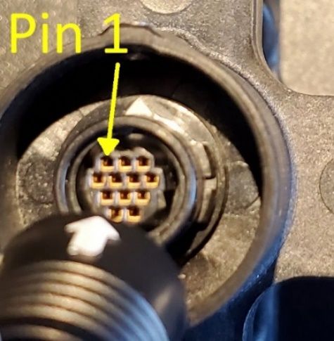
0 Release Date 9 July 2021 Anemoment LLC
A NEMOMENT LLC
TriSonica Mini Sensors: User Manual
2021 Anemoment LLC
353 Main Street
Longmont, CO 80501
Phone 720.600.7241 • Fax 720.223.7504
Email: info@anemoment.com
1 Release Date 9 July 2021 Anemoment LLC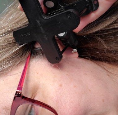
NOTES:

Sensor Unit Numbers: ___________________________________________________

Purchase Date: _________________________________________________________

2                                 Release Date 9 July 2021          Anemoment LLC
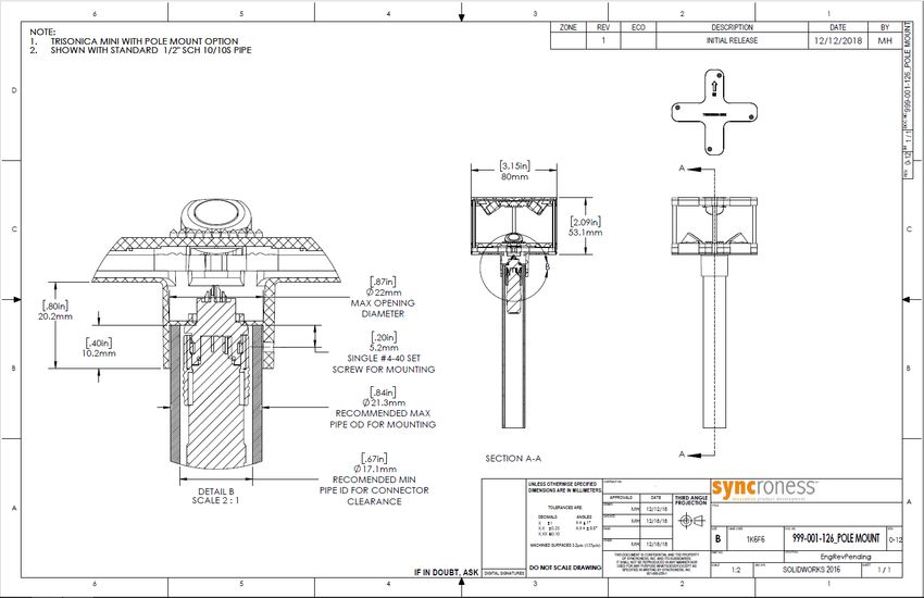
Table of Contents
Hello World! ............................................................................................................................... 5
    Guide to User Manual ............................................................................................................. 5
    The TriSonica Mini Family of Products ..................................................................................... 5
    Tell Us!.................................................................................................................................... 6
    Limitation Alerts...................................................................................................................... 6
       Compact Fluorescent Lamps ................................................................................................ 6
       Electro-Mechanical Motors and Magnetic Sensors .............................................................. 6
       Ice and Snow ....................................................................................................................... 7
       Just the Facts, Ma’am .......................................................................................................... 7
       Sorry, No Apples Today ....................................................................................................... 7
       Wind Tunnels & Ultrasonic Frequency ................................................................................. 7
TSM Body, Drawings, & Mounting Specifications....................................................................... 9
    TSM Sensor Body Composition ................................................................................................ 9
    Orientation ............................................................................................................................. 9
    TSM-FB ................................................................................................................................... 9
       Considerations for User-Supplied Mounting Platform for TSM-FB ...................................... 10
       TSM-FB Tripod Mounting Plate .......................................................................................... 10
    TSM-PM ................................................................................................................................ 10
       TSM-PM Tripod Adapter .................................................................................................... 10
Connecting Up .......................................................................................................................... 11
    TSM-FB ................................................................................................................................. 11
       Connecting the TSM-FB to Other Anemoment Products .................................................... 11
    TSM-PM ................................................................................................................................ 12
       Connecting the TSM-PM to Other Anemoment Products ................................................... 14
Data Output ............................................................................................................................. 15
    Viewing Serial Data Stream ................................................................................................... 15
    Serial Data Format ................................................................................................................ 15
    Custom Delimiters (New in 2.0) ............................................................................................. 16
    Error Codes ........................................................................................................................... 16
Customizing the TSM Sensor Configuration ............................................................................. 17
    Serial Communication - Defaults ........................................................................................... 17
    Serial Communication – Access Methods .............................................................................. 17
       Serial Menu (New in 2.0) ................................................................................................... 17
       Command Line Interface - Basic ........................................................................................ 18

3                                                             Release Date 9 July 2021                                     Anemoment LLC
Command Line Interface - Expert Mode .............................................................................21
       Application Programming Interface (New in 1.9) ................................................................23
    Triggering – TSM-PM Only .....................................................................................................23
    Display Command..................................................................................................................24
    Show, Hide, Tag, Untag, and Decimal Commands ..................................................................24
    Tag and Parameter Delimiters (New in 2.0)............................................................................24
Calibration Procedures and System Memory ............................................................................25
    Anemometer Calibration .......................................................................................................25
    Level Calibration ....................................................................................................................25
    Compass Calibration ..............................................................................................................25
    Wind Direction Scale Command (wd540) ...............................................................................27
    Non-Volatile Parameters .......................................................................................................27
TSM Sensor Meteorological Data Collection .............................................................................29
    Humidity................................................................................................................................29
    Absolute Pressure..................................................................................................................29
    Tilt .........................................................................................................................................29
    Compass ................................................................................................................................29
TROUBLESHOOTING your TriSonica Mini Sensor ......................................................................31
    Common Set-up Errors ..........................................................................................................31
       Symptom: The TSM Sensor doesn’t seem to be doing anything. ........................................31
       Symptom: There is no serial data coming from the TSM Sensor. ........................................31
       Symptom: The TSM Sensor sends garbled data. .................................................................31
    Updating TSM Sensor Firmware.............................................................................................32
    Updating TSM Sensor Bootloader (New in 2.0) ......................................................................32
WARRANTY AND DISCLAIMER ..................................................................................................31
    Limited Warranty...................................................................................................................31
    Warranty Returns ..................................................................................................................31
    Limitation of Liability .............................................................................................................31
LISTS OF FIGURES AND TABLES .................................................................................................32

4                                                             Release Date 9 July 2021                                      Anemoment LLC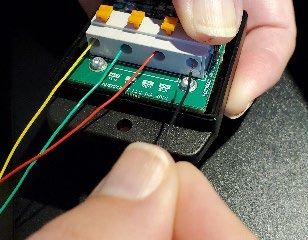
Chapter               Hello World!

         1
                          Welcome to the User Manual for the TriSonica Mini (TSM) family of
                          products from Anemoment.

                          We hope you find this information useful and wish you every success
                          in your research. We welcome comments and questions about this
                          manual by email at info@anemoment.com.

Guide to User Manual
This User Manual provides technical information to mount, connect, receive
data, and configure the TSM Sensors. For specific information on
FUNCTIONALITY, CONFIGURATIONS, plus TECHNICAL DATA and DRAWINGS,
use the Table of Contents in this User Manual to find information you seek.

The TriSonica Mini Family of Products
    1. TSM-WS          TriSonica Mini Wind Sensor (discontinued)

    2. TSM-FB          TriSonica Mini Wind and Weather Sensor – Flat Base

    3. TSM-PM          TriSonica Mini Wind and Weather Sensor – Pipe-Mount Base

    4. USB-Interface TriSonica Mini USB Interface Module

    5. TSM-FBSK        TriSonica Mini Flat Base Starter Kit includes one each: TSM-FB,
                       USB-Adapter, and USB A-to-B cable.

    6. TSM-PMSK        TriSonica Mini Pipe Mount Starter Kit includes one each: TSM-PM,
                       USB-Adapter, USB A-to-B Cable, and 2-meter single terminated cable.

As used in this Manual, the term “TSM Sensor” means the information specified applies to both
the TSM-WS and the TSM-PM.

5                                      Release Date 9 July 2021                 Anemoment LLC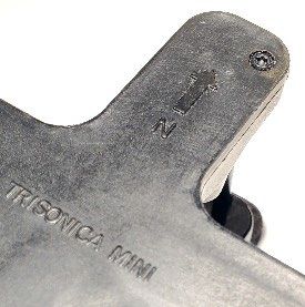
TRISONICA MINI SENSOR COMPARISON GUIDE
 Table 1: TSM SENSOR COMPARISON GUIDE

                                                    AVAILABLE
                  MOUNT          CONNECTION                                          ON-BOARD SENSOR
                                                  COMMUNICATION      DATA OUTPUT
                   STYLE            TYPE                                                    TYPES
                                                    PROTOCOLS

TSM-WS                                                                               •    Wind Direction
                                                                     Configurable
(discontinued)    Flat Base       4 Wires     •    EIA232                                 & Velocity
                                                                      ASCII String
                                                                                     •    Air Temp.
                                                                                     •    Wind Direction
                                                                                          & Velocity
                                                                                     •    Air Temp.
TSM-FB                                                               Configurable
                  Flat Base       4 Wires     •    EIA232                            •    Air Pressure
                                                                      ASCII String
                                                                                     •    Humidity
                                                                                     •    Tilt
                                                                                     •    Compass
                                                                                     •    Wind Direction
                                              •    EIA232                                 & Velocity
                 Pipe-Mount        12-pin     •    EIA422                            •    Air Temp.
TSM-PM                                                               Configurable
                  with 3 Set      Mating      •    EIA485                            •    Air Pressure
                                                                      ASCII String
                   Screws        Connector    •    LVTTL-UART                        •    Humidity
                                              •    Modbus (future)                   •    Tilt
                                                                                     •    Compass

 Tell Us!
 Did you spot a bug, a spelling error, or something that just didn’t make sense to you? We’d love
 to hear about it. Please send feedback to info@anemoment.com, with a detailed explanation of
 your concern. Screenshots and photos can be extremely helpful!

 Limitation Alerts
 Anemoment wants you to get the best possible use from your TSM Sensor investment, and we
 understand that each User has a unique idea they want to create. You know best what you are
 trying to accomplish. We know the TSM Sensors can help you access essential and actionable
 wind and weather data in new places and new ways, but we cannot promise that they can do
 everything or go everywhere the human mind can think up. We want to alert you to these
 points up front, to empower your decisions as you plan your project.

             Compact Fluorescent Lamps
             Many compact florescent lamps operate at ultrasonic frequencies that interfere with
             the operation of a TSM Sensor. If the TSM Sensor is operated near compact florescent
             lamps, erroneous and erratic readings may result. Turning off the compact florescent
             lamps or moving the TSM Sensor away from the CFL should result in proper instrument
             operation.

             Electro-Mechanical Motors and Magnetic Sensors
             Electro-mechanical motors generate magnetic fields; the effect of the field on a
             magnetic sensor varies by distance of the sensor to the motor, and by the speed (and
             variations of speed) at which the motor is operated. The magnetic sensor aboard your
             TSM Sensor will be affected by the field generated by motors nearby. We recommend

 6                                            Release Date 9 July 2021                   Anemoment LLC
that you consider the effects of magnetic fields arising from your unique use
configuration in both your hardware and software design.
Ice and Snow
The small size and light weight that are the hallmark of the TSM-FB and TSM-PM leave
no space for on-board heaters. These TSM Sensors are designed to function in outdoor
conditions; however, if ice or snow accumulate within the Sensor the acoustic pathways
between transducers can be blocked. While the dark coloring of the TSM-Sensors
facilitates natural solar removal of ice and snow, the TSM Sensors may not be the best
choice of sensor for sustained use in wintery weather.
Just the Facts, Ma’am
TSM Sensors combine powerful detection elements with a high-speed processor to
produce near-realtime data facts about atmospheric conditions at the site of the sensor.
The TSM Sensor transmits these collected data facts over wires in the form of a User-
configurable ASCII data stream. It is up to the User, however, to interpret this data in
the User’s unique situational context, which may require combination with additional
User-provided data or other post-processing. Anemoment is not responsible for such
additional data or processing.
Sorry, No Apples Today
The data stream from the TSM Sensor can be received, stored, and interpreted by the
User’s choice of device so long as it is connected to the Sensor by the proper
communications protocol. We recommend the use of a Terminal Emulator, such as Tera
Term, to review the data stream and to communicate with or configure the sensor.
Available for download at the Anemoment website is a rudimentary User interface app
for use on Windows™ operating systems; this app is not suitable for data logging
functions. The App’s OS choice is simply a result of skill-set limitations; we do not
presently have a timeline for developing an interface app for other operating systems.
Wind Tunnels & Ultrasonic Frequency
Ultrasonic anemometers operate by generating ultrasonic pulses and measuring the
time of flight of those sound pulses between transducers. The time-of-flight
measurements can be disturbed by external noise sources in or near the same
frequency band used by the ultrasonic anemometer’s transducers. (The TSM Sensors
operate in the 60KHz ultrasonic frequency range) We have found that some wind
tunnels generate ultrasonic noise that can cause erroneous readings from the
anemometer. This is not an indication of failure of the anemometer, but an artifact of
using the anemometer in what is to it an ultrasonically noisy environment.
7 Release Date 9 July 2021 Anemoment LLC8 Release Date 9 July 2021 Anemoment LLC
Chapter                 TSM Body, Drawings, & Mounting Specifications

         2
TSM Sensor Body Composition
The bodies of the TSM Sensors are injection molded of DuPont
Performance Polymer Zytel® glass reinforced nylon for long-term
performance in outdoor environments. Over time the sensor acquires a
weathered-gray patina, ideal for minimizing visual presence of the
system. The connecting posts are carbon fiber tubes.

Orientation                                                                  Figure 1: NORTH INDICATOR
The TSM Sensors have a “north” arrow indicator “N” marked on one of the upper arms. Airflow
passing directly into the “N” will return ZERO degrees for wind direction, regardless of the actual
orientation of the TSM Sensor.

TSM-FB
The TSM-FB features a flat base with four mounting points for connecting to a User-supplied
mounting platform.

                                     Figure 2: TSM-FB DRAWING

9                                         Release Date 9 July 2021                  Anemoment LLC
Considerations for User-Supplied Mounting Platform for TSM-FB
The User-supplied mounting platform should be a flat plate having a 5-mm hole in the
center for the connecting wires, and 5.5-mm hole positioned at the Gore-Tex™ Vent to
allow for water vapor and air pressure exchange.
TSM-FB Tripod Mounting Plate
Anemoment offers an optional 3d-printed mounting plate for attaching the TSM-FB to a
standard platform or camera tripod. This mounting plate features a brass ¼-20 threaded
insert.
TSM-PM
The TSM-PM has a circular connector to mount over a standard ½” DIN15 Schedule 10 pipe or
22-mm Carbon Fiber Tube. The pipe must be a thin wall type, as indicated by the Schedule 10
designation, to allow an inside diameter wide enough to let the mating cable connector pass
through the pipe.
Before fitting the TSM-PM to the pipe, thread the mating cable through the pipe and snap the
cable connector to the TSM-PM base connector. Then place the TSM-PM over the pipe and
tighten the three set screws to secure. For a detailed description of the internal wiring of the
connector and cable specifications please see Chapter 3: CONNECTING.
Figure 3: TSM-PM DRAWING
TSM-PM Tripod Adapter
As an optional accessory, Anemoment offers a 3d-printed pipe-simulating adapter for
attaching the TSM-PM to a standard platform or camera tripod. This mounting adapter
features a brass ¼-20 threaded insert.
10 Release Date 9 July 2021 Anemoment LLCChapter Connecting Up
3
Getting power in and data out – Your TSM Sensor will work best if
you give careful attention to the information in this Chapter.
TSM-FB
Exiting the base of the TSM-FB are four unterminated wires for User hook-up. The wires are
color coded to indicate the purpose of each.
• is 9V to 36V.
• is RS-232 TxD (Serial Data Out of the TSM).
• is RS-232 RxD (Serial Data into the TSM).
•Black is Ground and the serial connection return.
Figure 4: TSM-FB WIRES
Specially configured TSM-FB may have different color wires in the
place of or in addition to these four. Please refer to instructions accompanying
the specially configured TSM-FB for more information.
Connecting the TSM-FB to Other Anemoment Products
• USB ADAPTER:
Open the Adapter case, and insert the wires exiting the
TSM-FB into the terminal block by color as labeled on the
circuit board. Then connect the Adapter to a computer
using the USB cable. A helpful video demonstrating this Figure 5: TSM-FB to
connection is available at Anemoment.com/resources/. USB ADAPTER INSERTION
• DATA LOGGER (Circuit Board Only):
The screw terminals on the Data Logger are labeled “A” and “B”. Use the “A” terminals
to attach a single TSM-FB; use both “A” and “B” terminals to attach two TSM-FBs to the
Data Logger board. Insert each wire into the appropriate screw terminal hole and
tighten.
Table 2: TSM-FB to DATA LOGGER SCREW TERMINAL WIRING POSITIONS
YELLOW Wire RED Wire GREEN Wire BLACK WIRE
Single TSM-FB A4 A6 A5 A3
Second TSM-FB B4 B6 B5 B3
11 Release Date 9 July 2021 Anemoment LLC• DATA LOGGER (in WEATHER-TIGHT BOX):
Use a single terminated cable to connect the TSM-FB to a Data Logger in Weather Tight
Box via the 12-pin Circular connector port on the outside of the box. Connect the wires
exiting the TSM-FB to wires accessed in the blunt-cut end of the cable by carefully
matching as follows:
Table 3: TSM-FB to BLUNT-CUT CABLE MATCHING
TSM-FB Wires YELLOW Wire RED Wire GREEN Wire BLACK Wire
Cable Wire BROWN Wire YELLOW Wire BLUE Wire RED Wire
TSM-PM
The TSM-PM contains a female 12 Pin circular connector
that connects to a male 12 Pin Circular IP67 connector.
Cables with connectors may be purchased from
Anemoment in 2m, 5m, 10m, and 20m lengths.
Customized cables and mating connectors may be
purchased directly from Samtec.com (see
https://www.samtec.com/products/mcp for information
about their line of products and customizability).
Table 4 shows the pin-out diagram for the signal
connections and positions within the connector in Figure 6: 12-PIN FEMALE CONNECTOR
reference to looking at the bottom of the connector,
with Pin 1 at upper left.
The cable internal wire colors and pin description are given in Table 5.
Table 4: TSM-PM PIN OUT DIAGRAM
12 Release Date 9 July 2021 Anemoment LLCTable 5: TSM-PIN DESCRIPTION & CABLE WIRE COLORS
Pin # Wire Color Signal Name Description
1 BROWN VIN Voltage Input of 9V to 36V
Ground connection. Only one of the GND
connections are required for proper
2 RED GND
operation. Multiple GND connections are
provided as a convenience for system wiring.
Synchronizing Trigger input. This input allows
3 ORANGE Trigger multiple instruments to synchronize their
sampling to a common signal.
Serial Transmit data output in EIA232 Mode
4 YELLOW TX+
and TX+ data output in EIA422 mode.
Serial Transmit data output TX- in EIA422
5 GREEN TX-
mode. Not used in EIA232 mode.
Serial Receive data input in EIA232 Mode and
6 BLUE RX+
TX+ data output in EIA422 mode.
Serial Receive data input RX- in EIA422 mode.
7 VIOLET RX-
Not used in EIA232 mode.
8 GRAY URX 3.3V LVTTL UART Serial Data Input.
Ground connection.
9 GND
See the description for Pin #2
Force Single Ended Serial mode. When this
pin is connected to GND the TSM will start in
10 BLACK 232 EIA232 or LVTTL-UART mode with the
settings of 115200,8,N,1 regardless of the
software settings of the instrument.
LIGHT
11 UTX 3.3V LVTTL-UART Serial Data Output.
GREEN
Ground connection.
12 PINK GND
See the description for Pin #2
13 Release Date 9 July 2021 Anemoment LLCConnecting the TSM-PM to Other Anemoment Products
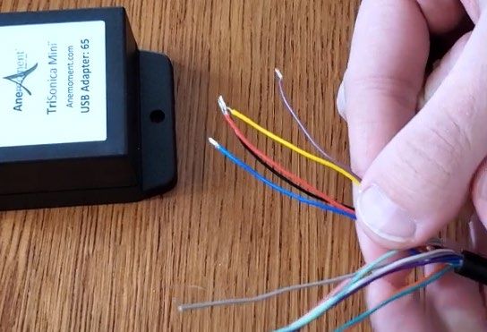
• USB ADAPTER: Use the Single-Terminated
blunt-cut cable to connect the TSM-PM to
the USB Adapter. Separate out and strip
3mm of the ends from the Yellow, Blue, Red,
Black, and Brown wires from the blunt-cut
end of the cable.
NOTE: to some eyes the Brown wire appears
mauve or lilac in color. If you find it difficult to
identify the Brown wire because you see two
purple-ish wires, the Brown wire is the lighter
“not” rich-violet one. Figure 7: SEPARATING THE WIRES
Open the adapter case and insert the wires into the terminal block holes as follows:
Table 6: TSM-FB to DATA LOGGER SCREW TERMINAL WIRING POSITIONS
1 2 3 4
BROWN BLUE YELLOW RED & BLACK
CAUTION : Because the cable contains 12 wires designed to
accommodate the multi-protocol capable TSM-PM, these color
assignments do not match the labels printed on the USB Adapter
circuit board.
A helpful video demonstrating this connection is
available at Anemoment.com/resources/.
• DATA LOGGER (Circuit Board Only): Use a Single-Terminated blunt-cut cable to
connect the TSM-PM to the USB Adapter. Separate out and strip 3mm of the ends from
the Red, Brown, Blue, Yellow, Orange, and Black wires from the blunt-cut end of the
cable.
The screw terminals on the Data Logger are labeled “A” and “B”. Use the “A” terminals
to attach a single TSM-FB. Use both “A” and “B” terminals to attach two TSM-FBs to the
Data Logger board.
Insert each wire into the appropriate screw terminal hole and tighten.
Table 7: TSM-PM DATA LOGGER SCREW TERMINAL WIRING POSITIONS
RED BROWN BLUE YELLOW ORANGE BLACK
Single TSM-PM A3 A4 A5 A6 A7 A8
Second TSM-PM B3 B4 B5 B6 B7 B8
• DATA LOGGER (in WEATHER-TIGHT BOX): Connect these items by snapping in place
the connectors at both ends of a Double-Terminated cable.
14 Release Date 9 July 2021 Anemoment LLCChapter Data Output
4
The TSM Sensor collects a wide variety of environmental data. This
Chapter explains what you see in the data stream. Chapter 5 will tell
you how to customize which variables should appear, how they
should be labeled, and how often the information should arrive.
Viewing Serial Data Stream
With the TSM Sensor connected to a computer using the USB Adapter or similar User-designed
device that both supplies power to the TSM Sensor and allows data pass-through, the Serial
Data Stream from the TSM Sensor can be viewed by using a Terminal Emulator app such as Tera
Term or with the TriSonica Mini User App downloadable at https://anemoment.com/resources/.
Serial Data Format
The TSM outputs data in an ASCII character string ending with carriage return and line feed
characters.
Each line is a single record of all the measured parameters contained in a single sample. The
parameters on an output line are separated by two spaces, or by a single space and a negative
sign. The User may elect to use optional data tags to indicate the measurement associated with
the value; the tags can be turned on or off for each individual type measurement. For more about
tags, see Show, Hide, Tag, Untag, and Decimal Commands.
A sample of the output without tags:
05.2 112 -01.9 04.7 01.1 22.6
05.3 107 -01.5 04.9 01.3 22.2
The columns in this example in order are
Wind Speed - Wind Direction - U-Vector - V-Vector - W-Vector - Temperature.
A sample of the output data with tags:
S 05.2 D 112 U -01.9 V 04.7 W 01.1 T 22.6
S 05.3 D 107 U -01.5 V 04.9 W 01.3 T 22.2
S= Wind Speed
D= Wind Direction
U= U-Vector
V= V-Vector
W= W-Vector
T=Temperature
15 Release Date 9 July 2021 Anemoment LLCCustom Delimiters (New in 2.0)
The delimiters for the tags and parameters are customizable. In this example a colon is used
after the tags in place of the space and a comma is added after the measurement value. The
default values are a space character for both the tags and the parameters to be compatible with
previous versions. Details on how to use this feature are given with the paramdelim and
tagdelim commands.
S: 05.2,D: 112,U:-01.9,V: 04.7.W: 01.1,T: 22.6
S: 05.3,D: 107,U:-01.5,V: 04.9,W: 01.3,T: 22.2
Error Codes
When the TriSonica Mini firmware detects an error, it outputs an error code in the data stream
in all the affected parameters. All error codes appear in the format of “-99.x”. The decimal value
of the error code varies with the error type.
When an error code is in the output, use the “diagnostic” command to get information about
the error.
One of the most common reasons for an error is an ultrasonic pathway blockage. Ice, snow, or
some other physical material is preventing the ultrasonic signal reception. Clearing the blockage
returns the unit to normal operation.
16 Release Date 9 July 2021 Anemoment LLCChapter Customizing the TSM Sensor Configuration
5
The TSM Sensor collects a wide variety of environmental data. By
connecting the TSM Sensor to a computer. This Chapter explains
how to communicate to the TSM Sensor, which variables should
appear, how they should be labeled, and how often the data packets
should arrive.
Serial Communication - Defaults
The TSM Sensor is configured by default to these serial parameters:
• Baud Rate: 115,200
• Data Bits: 8
• Parity: None
• Stop Bits: 1
The TSM Sensor starts generating data about one second after power up, and outputs data
continuously when in sampling mode. You can tell the TSM Sensor is working by listening for a
quiet rapid clicking sound made by the transducers. (This sound is a mechanical artifact from a
transducer initiating an ultrasonic sound, not the ultrasonic sound itself).
Serial Communication – Access Methods
There are several access methods by which the User can enter configuration instructions for the
TSM Sensor. The choice of method is largely up to User preference, though some higher level
instructions are available only through more expert access methods. Each access method is
explained.
Serial Menu (New in 2.0)
Pressing the ESC key brings up a serial menu for configuring basic settings. Please note that not
all settings are accessible from this menu.
If no User input is received while the Serial Menu is inactive for one minute, the TSM returns to
sampling mode and any changes made are not stored in the non-volatile memory.
17 Release Date 9 July 2021 Anemoment LLCTable 8: SERIAL MENU FUNCTIONS
MAIN MENU FUNCTIONS AVAILABLE WITHIN MENU OPTION
OPTION
A. Serial Setup Serial Baud, Parity, and (TSM-PM only) Serial Protocol Selection
B. Data Output List of Output Parameters, indicating whether they are Enabled, how
Setup many Decimals are displayed, the Units for the parameters, and the data
Tag. From this menu, press the menu letter key to access submenus that
control these Output Parameters.
C. Instrument Data Output Rate, Orientation, and (TSM-PM only) Trigger parameters
Setup
D. Calibration Walks the User through calibration steps for User-performed wind, level,
and compass calibration.
• To calibrate the wind sensor, the User places the instrument in a
zero-airflow chamber equipped with a temperature sensor, and
the User enters a value for local humidity.
• The level sensor calibration requires a surface that is known to
be level and that can support the TSM level to the surface.
• Compass calibration requires the User to twist and rotate the
sensor in a three-dimensional figure-eight fashion, in similar
manner to how cell phones calibrate an internal compass.
E. Diagnostic Runs built-in diagnostics and displays the results.
G. Instrument Resets the instrument, clearing all volatile memory, restoring to non-
Reset volatile memory settings.
X. Exit without Exits the menu with the changes the User has made, allowing the User
storing changes to apply the changes temporarily. These changes are not stored in the
non-volatile memory and will be lost after a system reset/system power-
down.
0. Exit Exits the menu and stores changes in non-volatile memory. These
changes are retained even after a system reset/system power-down
Command Line Interface - Basic
To enter command line interface (CLI) mode, press Ctl+C. The TSM Sensor stops
sampling and provides a User prompt: “>”. New in 2.0, if no User input is given within
one minute, the TSM Sensor returns to sampling mode.
Details of all available commands and their parameters are accessed within the
Command Line interface by typing “help” at the User prompt. For reference, some of the
commands are listed below. Parameters are indicated with “” characters; you
will replace the angle brackets and the text with the parameter value. Parameters
shown within square brackets “[“ and “]” are optional.
NOTE: We attempt to make the TSM CLI self-documenting, so with
future Firmware Releases, the detailed help for each command may be
more current than appears in the following table.
18 Release Date 9 July 2021 Anemoment LLCTable 9: Serial Commands in the Command Line Interface
COMMAND DESCRIPTION
help Displays a list of CLI commands.
help The command word “help” followed by the
name of another command displays detailed
help for that command.
exit Leave the CLI and return to sampling.
baudrate [ [now]] Show or set the current baud rate
calibrate [] Start an anemometer calibration cycle. See the
anemometer calibration Chapter of this
document for more details about the
anemometer calibration procedure.
compasscalibrate YES Start a compass calibration cycle. (Not available
on TSM-WS) See the compass calibration
Chapter of this document for more details
about the compass calibration procedure.
decimals [] Set the number of decimals places of a Display
Parameter or a Group of Parameters. See the
Show, Hide, Tag, Untag, and Decimal Commands
section in this document.
declination [] Set/Read the true heading declination offset
Diagnostic [details|clear] Performs a self-diagnostic and reports problems
found with the TSM. The details parameter
gives a more detailed diagnostic output. The
clear parameter clears the error counts display
of the details parameter
display Show the current Display Mode settings. See the
Display Commands section in this document.
expert enable|disable Enable or Disable Expert Menu Command Items.
See the section on Expert Mode
hide [] Hide Display Parameter Groups. See the Show,
Hide, Tag, Untag, and Decimal Commands
section in this document.
levelcalibrate YES Start a level calibration cycle. (Not available on
TSM-WS) See the compass calibration section of
this document for more details about the
compass calibration procedure.
19 Release Date 9 July 2021 Anemoment LLCCOMMAND DESCRIPTION
nvwrite Writes parameter data to non-volatile memory.
See the section about Non-Volatile Parameters.
outputrate [] Set or Show the data output rate of the sampled
data
parity [odd|even|none [now]] Set or Show the current parity setting
programupdate [YES] Use the TriSonica Mini Program Update Utility
provided by Anemoment.
show [] Show Display Parameter or Groups. See the
Show, Hide, Tag, Untag, and Decimal Commands
section in this document.
systemreset Software Reset.
tag [] Display the ID Tag of a Display Parameter or a
Group of Parameters. See the Show, Hide, Tag,
Untag, and Decimal Commands section in this
document.
triggertype [] Set or Get the sampling trigger type – TSM-PM
Only
trisonicaid Set or Show TriSonica User Defined ID
units [ [units]] Sets or Displays the units value for all adjustable
parameters
untag [] Remove the ID Tag of a Display Parameter or a
Group of Parameters. See the Show, Hide, Tag,
Untag, and Decimal Commands section in this
document.
version Displays software version and build numbers
wd540 [] Set or Show the Wind Direction 540 Degree
Mode
20 Release Date 9 July 2021 Anemoment LLCCommand Line Interface - Expert Mode
When expert mode is enabled, these extra commands are present in the help menu. It is
recommended that you understand the effects of these commands before you use
them.
Table 10: Serial Commands In Expert Mode
COMMAND DESCRIPTION
averagesize [] Set or Show the size of the average of samples.
This command specifies the number of internal
samples to average before generating an
output, when combined with the samperate
command below it affects the output data rate.
For simplicity, it is better to use the outputrate
command in the basic menu.
digitalgain [] Get or Set the digital gain. Digital, or software,
gain is set by the calibration command.
Changing digitalgain can affect the stability of
your output data.
distance [] (x1 or x4) Set or Show the distance between transducers.
This is one of the calibration factors set during
the calibration cycle. If you enter the value as a
single number, it will be applied to all four
distances. If you enter four values, they will be
applied respectively to the four distance values.
The mechanical distance between transducers
of a TSM is 0.03486.
humiditycalibrate [slope |offset ] Gets or sets the slope and offset humidity
calibration factors. This command allows the
Users to add their own slope and offset values
to the humidity senor output. Note that the
humidity is transferred through the Gore-Tex
Pvent on the bottom of the TSM and can take
several minutes to equalized with there is a
rapid change in humidity. Using the command
without parameters returns the current slope
and offset values. Providing the slope and offset
parameter values sets these values for the
humidity sensor.
lowpower Sets or shows the low power configuration
parameters. Low power mode can be woken
internally, or externally. Do not use the external
wake mode on a TSM-WWS.
21 Release Date 9 July 2021 Anemoment LLCCOMMAND DESCRIPTION
offset [] (x1 or x4) Set or Show the offset value for all paths. This is
one of the calibration factors set during the
calibration cycle. If you enter the value as a
single number, it will be applied to all four
distances. If you enter four values, they will be
applied respectively to the four distance values.
The offset value compensates for variations in
manufacturing.
orientuv [std | ati | otsm] Set or View the UV Wind Vector Output
coordinate system. There are some different
definitions for the meanings of the U and V axis.
The “std” setting defines positive U as being from
the West, and positive V as being from the
South. The “ati” setting defines the positive U as
being from the North, and positive V as being
from the West. The “otsm” setting matches the
original TriSonica Mini output definition of
positive U as being form the North, and positive
V as being from the East.
paramdelim [ | space] Get or Set the Parameter delimiter for all
Display Parameters
pressurecalibrate [slope |offset ] Gets or sets the slope and offset pressure
calibration factors. This command allows the
Users to add their own slope and offset values
to the pressure senor output. Note that the
pressure is transferred through the GorTex vent
on the bottom of the TSM and can take several
seconds to equalized with there is a rapid
change in pressure. Using the command
without parameters returns the current slope
and offset values. Providing the slope and offset
parameter values sets these values for the
pressure sensor.
protocol [232|422 [now]] Show or set the current serial protocol setting.
The command only works for the TSM-PM,
where the EIA422 signals are brought out to the
connector. This is the software command to
select between EIA232 and EIA422 modes. The
“now” parameters makes the change
immediately, otherwise the change happens
after a system reset. – TSM-PM Only
22 Release Date 9 July 2021 Anemoment LLCCOMMAND DESCRIPTION
samplerate [] Set or Get the internal sample frequency. This
command changes the internal sampling rate
and when combined with the averagesize
command above affects the output data rate.
For simplicity, it is better to use the outputrate
command in the basic menu.
shadowcorrect [0|1] Enable or disable the shadow correction
calculations of the TSM. 1 = enable, 0 = disable. It
is not recommended that the User turn off the
shadow correction.
tagdelim [ | space] Get or Set the tag delimiter for all Display
Parameters
tagid Set the tag id to in the specified parameter
triggertype [] Get or set the trigger parameters. See the
section on triggering.
Application Programming Interface (New in 1.9)
The TSM provides a method to simplify computer command automation. It is a variation
on the CLI interface and uses the same commands as the CLI interface. The API
commands are sent to the TSM during sampling mode. The command is enclosed in
curly braces “{” and “}” without a carriage return or line feed character. One command
per set of curly braces. The open curly brace “{” instructs the TSM that a API command
is starting, and the close curly brace “}” indicates the end of the command. When the
close curly brace “}” is received the command is executed and the results returned
within the curly braces. This is not compatible with the JSON protocol.
Triggering – TSM-PM Only
The TSM-PM includes a trigger line. Triggering can be internal or external and can be adjusted to
trigger on the rising or falling edge of the external signal. The parameters “posedge” and
“negedge” for the triggertype command make this selection.
The three trigger modes are:
1. Internal Trigger: The TSM uses its own internal timer for sample triggering and runs
asynchronous to other instruments. (NOTE: The TSM-FB only has Internal Triggering.)
2. External Trigger: When an external trigger is received the TSM-PM takes the number of
samples specified in the averagesize command at the configured samplerate. When this
sampling is complete the output is generated and transferred over the serial port. The
TSM-PM then waits until the next trigger before sampling again. If the trigger is too fast
to complete all the samples, the TSM-PM will shorten the number of samples taken to
maintain the external trigger rate.
23 Release Date 9 July 2021 Anemoment LLC3. Sync: The sync trigger mode adjusts the internal trigger sampling to align with the sync
trigger, otherwise the TSM-PM operates on its internal trigger. For instance, this is
useful for aligning samples to a GPS Pulse Per Second clock so multiple instruments can
trigger simultaneously without being connected to the same trigger. Sync pulses can
have a very long time between pulses.
Display Command
The ‘display’ command prints a
table indicating the name and
description of each signal
available, whether it is tagged
or not, what the tag value is,
how many decimals are Figure 8: Display Command Output Example
displayed, whether the signal is
enabled to be added to the serial output string, and the units for each measurement.
Show, Hide, Tag, Untag, and Decimal Commands
The ‘show’, ‘hide’, ‘tag’, ‘untag’, and ‘decimal’ commands operate similarly. They enable a
measurement, disable a measurement, display the tag for a measurement, remove the tag for a
measurement, or adjust the number of decimals for an output; respectively.
When invoked without a parameter, they display the options available. The ‘show’ command
only lists the values that are available to be shown, similarly the ‘hide’ command only lists the
values that can be hidden. (The ‘hide’ command provides a convenient list of all values currently
being displayed.) The ‘tag’ and ‘untag’ commands show only the values available to be tagged
and untagged, and the ‘decimal’ command only lists the values that allow changing their decimal
resolution.
Tag and Parameter Delimiters (New in 2.0)
The display output can be modified by changing the delimiters between the tag and the
parameter value, and between measurement values. The tag delimiter is a single character
display immediately after the parameter tag and is controlled by the tagdelim command. The
delimiter between measurement values is a single character displayed immediately after the
parameter value is displayed. This value is controlled by the paramdelim command. The default
value for both delimiters is a space character.
24 Release Date 9 July 2021 Anemoment LLCCalibration Procedures and System Memory
Chapter
6
Every TSM Sensor is tested and calibrated prior to shipping.
However, the User can re-calibrate the sensor to acclimate to unique
use cases or local conditions by following these directions.
Anemometer Calibration
Place the TSM inside a small container to reduce the airflow to as close to zero as possible. Care
must be taken to eliminate acoustic reflections from hard sides and to not block the acoustic
pathways. There should be some sound absorbing material on any flat walls that could reflect
sound back towards the TSM. A small box with acoustic absorption foam is ideal. However, in a
pinch you can successfully calibrate a TSM by loosely wrapping a coat or towel around it. The
main thing is to provide a zero-wind environment, and to know the temperature, and ideally the
humidity, of the air volume where the TSM is enclosed.
Type “calibrate []”
Where the = xx.x in °C temperature and = xx.x in % relative humidity. If humidity is
not supplied, then 50% is assumed.
The calibration cycle takes ten seconds. You will see dots printed on the serial console indicating
progress, and the serial prompt will return when the calibration is completed. Enter “nvwrite”
to store the new calibration values in non-volatile memory.
Level Calibration
The calibration function of the level is simply an offset adjustment for the accelerometer
contained in the TSM. Place the TSM on a known level surface such that the bottom surface of
the TSM is parallel with the level surface. The wires of the TSM will prevent placing the TSM
directly on the level surface. With the TSM in a known level configuration execute the
“levelcalibrate” command. Enter “nvwrite” to store the values in non-volatile memory.
Compass Calibration
The compass calibration acclimates the compass module in the TSM to the local magnetic field.
Start the compass calibration by using the “compasscalibrate” command. The compass
calibration is active for fifteen seconds, during this time tilt and rotate the TSM into as many
orientations as possible using a three-dimensional figure eight pattern. Enter “nvwrite” to store
the values in non-volatile memory.
25 Release Date 9 July 2021 Anemoment LLCLet’s talk Calibration – It’s all in the Math and Physics
Inside each TriSonica Mini sensor a high-speed processor running custom
software applies principles of math and physics to extract atmospheric data from the
tiny changes in how quickly soundwaves travel along paths between pairs of
transducers.* By sending and detecting sound waves along multiple acoustic paths
(TriSonica products use 4 acoustic paths intersecting the three spatial axes), three-
dimensional information about atmospheric conditions at the site of the sensor can
be obtained.
Our custom software results from decades of experience in sonic
anemometry software design (including creation of the software currently featured
in Applied Technologies, Inc. products). Our software also reflects years of testing
and refinement for the unique geometry of the TriSonica Mini sensor through fluid
dynamic modeling, digital signal processing, and wind-tunnel based shadow-
correction verification.
This software enables the sensor to identify precisely how long it takes for
sound to pass between two transducers. As a result, the only calibration
measurement of importance is knowing the exact distance of the acoustic paths
between the pairs of transducers.
Before leaving our facility, each TriSonica Mini undergoes calibration to
identify that exact distance for each acoustic path. We do this by locking down the
TriSonica Mini in a zero-airflow chamber fitted with an independent temperature and
humidity sensor. After an appropriate time for the chamber conditions to settle, the
calibration routine of our software runs the math and physics equations backwards,
in a sense, to calculate the exact distance between pairs of transducers, down to the
micron level. These results are stored in the TriSonica Mini sensor’s memory to
supply the known distance from which time-of-flight changes are detected. Packed in
the box with each TriSonica Mini sensor you will find a certification that the sensor
passed this power-up and calibration testing, and the distance values were stored.
The TriSonica Mini sensor is resilient, functioning well under many adverse
conditions. However, if your sensor has been knocked about, or was skewed during
attachment to your custom mounting device, the distance between pairs of
transducers may have changed slightly. If you believe this has been the case, you can
re-calibrate your sensor in the field using the Calibrate command. You will need to
create a zero-air condition around your sensor, and to enter in the temperature and
humidity values for your location. This will allow your sensor to find the precise
lengths of the acoustic paths for improved data accuracy.
*For a brief and elegant explanation of the math and physics of sonic anemometry, see Section II of “A Martian
Acoustic Anemometer”, D. Banfield, et al., THE JOURNAL OF THE ACOUSTICAL SOCIETY OF AMERICA 140, 1420-1428
(2016) https://doi.org/10.1121/1.4960737. The truly curious may enjoy Dr. J. Chandran Kaimal’s history of the
science, in “Advances in Meteorology and the Evolution of Sonic Anemometry”, available at
https://www.apptech.com/wp-content/uploads/2016/08/Evolution-of-Sonic-Anemometry.pdf.
26 Release Date 9 July 2021 Anemoment LLCWind Direction Scale Command (wd540) Wind direction can be displayed in a 0-to-360-degree format or in a 0-to-540-degree format for strip chart type displays. The 540-degree mode prevents full scale shifting of data when the wind direction is around 0, where it moves from 359 to 0 to 359. Otherwise, the data makes a single large transition once at 540 degrees and again at 180 degrees to display data. Non-Volatile Parameters The TriSonica Mini operates with a copy of its configuration parameters in volatile memory (RAM). When changes are made using the CLI, the parameters are updated in the volatile memory. These changes will be lost when the unit restarts and pulls the parameters out of Non- Volatile Memory (Flash). To copy the parameter changes made in volatile memory to the non- volatile memory use the “nvwrite” command. The changes will then be remembered during a restart. 27 Release Date 9 July 2021 Anemoment LLC
28 Release Date 9 July 2021 Anemoment LLC
Chapter                 TSM Sensor Meteorological Data Collection

        7
                          The TSM Sensor detects humidity, absolute pressure, accelerometer
                          (tilt), and magnetometer (compass) conditions at the location of the
                          sensor.

Humidity
The humidity sensor is located inside the TriSonica Mini and depends on the water vapor
transfer membrane (white Gortex dot) to keep the humidity inside the same as outside the unit.
This causes a delay in the humidity reading when the humidity change. This delay can be up to
an hour for very large humidity changes, such as moving the unit from a 90% environment to a
30% environment. Normal environmental humidity changes that happen more slowly
experience a shorter latency.

The Humidity is determined by calculating the dew point inside the anemometer, it is assumed
then that the dew point is the same inside and out. The average of the ultrasonic temperature is
used to calculate the humidity from the dew point.

An issue seen during testing occurred when the TriSonica Mini was removed from a warm 90%
humidity environment to a cooler 30% environment. The quick change caused condensation
inside the unit and it displayed humidity greater than 100% until the condensation evaporated
and equalized through the vent.

Absolute Pressure
The absolute pressure sensor is located inside the TriSonica Mini and depends on the water
vapor transfer membrane to keep the pressure inside the same as outside the unit. A slight
delay is noticed with rapid pressure changes.

Tilt
An accelerometer is located inside the TriSonica Mini. Since the mounting of the TriSonica Mini
affects the tilt measurement, the offsets have not been set during manufacturing. The
“levelcalibrate” command is provided to record the accelerometer values and use them to
offset the measurement for level. The raw accelerometer outputs are also available.

Compass
A magnetic sensor, or compass, is located inside the TriSonica Mini. Since the heading reading of
the magnetic sensor is very dependent on the magnetic effects of the environment around it,
the heading is not calibrated during manufacturing. The “compasscalibrate” command is
provided for the User to calibrate the compass in the environment where it will be used. The
raw magnetometer outputs are also available.

To calibrate the heading, the User invokes the “compasscalibrate” command, then rotates and
tilts the unit in a three-dimensional figure eight, like how you calibrate the compass of other
handheld devices.

29                                       Release Date 9 July 2021                Anemoment LLC
30 Release Date 9 July 2021 Anemoment LLC
TROUBLESHOOTING your TriSonica Mini Sensor
 Chapter

       8
Common Set-up Errors
Symptom: The TSM Sensor doesn’t seem to be doing anything.
       Action: Place the TSM Sensor near your ear and listen for a
               quiet fast ticking sound.

       •   If you hear no sound, confirm the device the TSM
           Sensor is connected to has power.

       •   If the device has power, check that the USB port is
           providing power, and the TSM Sensor has been                Figure 9: Listen for TSM Sensor
           assigned an appropriate COM Port.                           Operation

       •   If the connected system is powered, check the TSM Sensor’s VIN and Ground
           connections. Refer to the CONNECTION Chapter for specific details. Note that VIN
           line is the only line that can handle voltages exceeding 5 volts.

       •   If you’ve checked this twice and you still hear no sound, please contact us at
           info@anemoment.com for further steps.

Symptom: There is no serial data coming from the TSM Sensor.
       Action: Refer to the CONNECTION Chapter to check to see whether you’ve swapped the
               Transmit and Receive data lines. If those are correct, check to see whether
               you’ve connected RS-232 wire to a UART input (such as on a Raspberry-PI,
               Arduino, BeagleBone or the like). Fix any mis-wired connections you have found.

Symptom: The TSM Sensor sends garbled data.
       Action: Check your power supply and your receiving unit to make sure there is a ground
               connection between the power supply, the serial port receiving data, and the
               TSM Sensor. If those are correct, check your baud rate and parity settings on
               your receiver; the TSM Sensor default transmission settings are 115200,8,n,1.

31                                      Release Date 9 July 2021                   Anemoment LLC
Updating TSM Sensor Firmware
Download the latest Firmware release at Anemoment.com/resources/ and save in the
Download directory. Connect the TSM Sensor that computer. From here, choose a method of
command access. (TeraTerm is offered as the Terminal Emulator example):
If using the TriSonica User APP_________________
• In the Settings Tab click “Browse…”
• Navigate to the downloaded file.
• Click “Update Software.”
• The TSM Sensor updates and the new version number will register on screen.
If using TeraTerm (Terminal Emulator)_____________
• With the TSM Sensor connected and streaming data, press CTRL+C.
• Type “programupdate YES”
• From the TeraTerm menu select the following: File Transfer YModem Send.
• Select the file to upload, and press “Enter.”
Updating TSM Sensor Bootloader (New in 2.0)
In the TriSonica Mini program memory are two programs, the TriSonica Sensor application, and
a bootloader. During a reset or power on, the bootloader checks to determine if the sensor
application is valid. If the sensor application is valid the bootloader turns over control to the
sensor application. If the sensor application is not valid, the bootloader presents a command
line interface with a limited set of commands: help, programupdate, systemreset, and
factoryreset. These commands perform the same functions described in Chapter 5 above.
Version 2.0 of the sensor application has a command to update the bootloader to the current
version. After updating the sensor application, enter the command line and enter the expert
mode with the command “expert enable”. Then use the command “bootloadupdate YES” to
update the bootloader.
32 Release Date 9 July 2021 Anemoment LLCWARRANTY AND DISCLAIMER
Chapter
9
Limited Warranty
Anemoment warrants to the purchaser that each Anemoment Product will be free from defects
in materials and workmanship for 90 (ninety) days from the date of sale. The Warranty shall not
apply
(i) to any Product that is abused, damaged by external causes, altered or misused; or
(ii) to any Product damaged due to improper installation or use.
Anemoment’s sole obligation under this Warranty shall be to repair, replace, or refund purchase
price of the applicable Product, at its sole option, provided that Anemoment is given timely
notice of the defect.
THE LIMITED WARRANTY REFERRED TO IN THIS SECTION IS THE ONLY WARRANTY, EXPRESS OR
IMPLIED, THAT ANEMOMENT MAKES WITH RESPECT TO THE PRODUCTS. ANEMOMENT
SPECIFICALLY DISCLAIMS ALL OTHER IMPLIED WARRANTIES, INCLUDING, WITHOUT LIMITATION,
THE IMPLIED WARRANTIES OF MERCHANTABILITY, FITNESS FOR A PARTICULAR PURPOSE, AND
NON-INFRINGEMENT. NO ADDITIONAL REPRESENTATION OF WARRANTY, INCLUDING BUT NOT
LIMITED TO: STATEMENTS OF CAPACITY, SUITABILITY FOR USE OR PERFORMANCE, WHETHER
MADE BY ANEMOMENT EMPLOYEES OR OTHERS SHALL BE CONSIDERED TO BE A WARRANTY BY
ANEMOMENT FOR ANY PURPOSE OR GIVE RISE TO ANY LIABILITY OF ANEMOMENT
WHATSOEVER.
Warranty Returns
For defective Products, please contact us at +1 (720) 600-7241 or info@anemoment.com to
make appropriate arrangements.
Limitation of Liability
ANEMOMENT SHALL NOT BE LIABLE FOR CONSEQUENTIAL, INCIDENTAL, SPECIAL, GENERAL,
DIRECT, INDIRECT OR ANY OTHER DAMAGES SUSTAINED BY ANY PERSON OR ENTITY FROM THE
USE OF THE PRODUCTS.
THIS LIMITATION OF LIABILITY SECTION APPLIES WHETHER THE ALLEGED LIABILITY IS BASED ON
CONTRACT, TORT, NEGLIGENCE, STRICT LIABILITY, OR ANY OTHER BASIS, EVEN IF ANEMOMENT
HAS BEEN ADVISED OF THE POSSIBILITY OF SUCH DAMAGE. THE FOREGOING LIMITATION OF
LIABILITY WILL APPLY TO THE FULLEST EXTENT PERMITTED BY LAW IN THE APPLICABLE
JURISDICTION.
31 Release Date 9 July 2021 Anemoment LLCYou can also read