Crowtail Starter Kit for Micro:bit - User Guide - Elecrow.com
←
→
Page content transcription
If your browser does not render page correctly, please read the page content below
Crowtail Starter Kit
    for Micro:bit
    User Guide
     V2.0   2020.02

C   2020 ELECROW All Rights Reserved.   www.elecrow.com
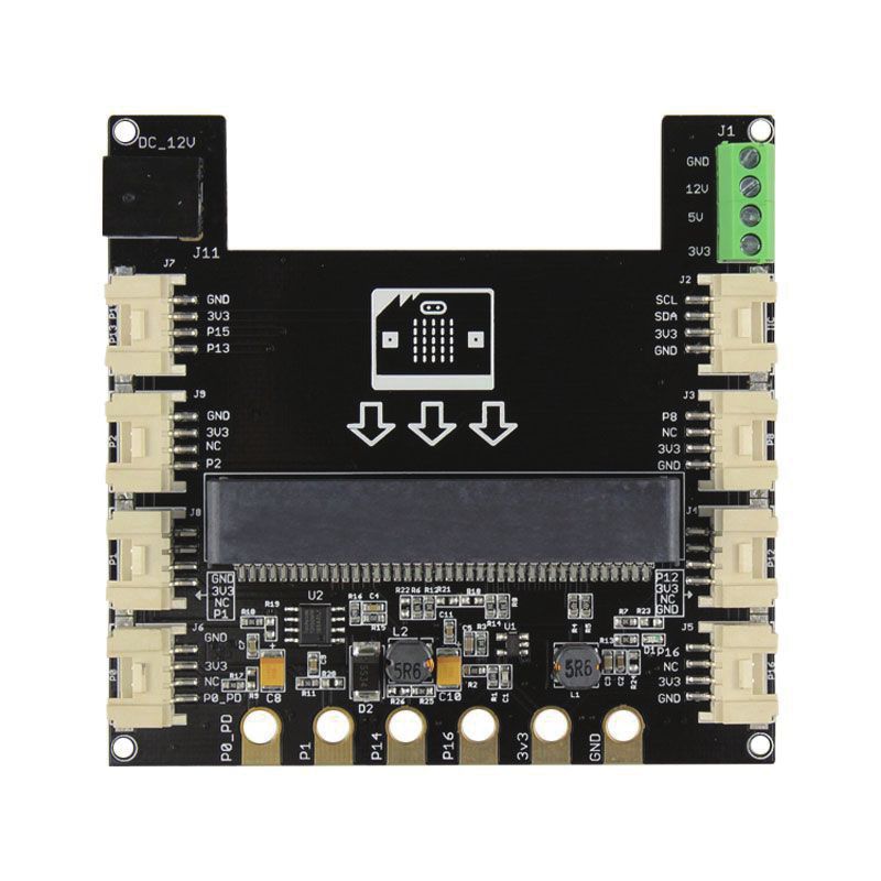
Table of Contents

Instruction                                                        1
Get to know micro:bit                                              2-6
Modules list                                                       7
What is Crowtail                                                   7-8
Exciting experiments                                               8
 • Experiment 1 Blinking an LED                                    8-9
 • Experiment 2 Switch light                                       10-11
 • Experiment 3 Micro:bit singer                                   11-13
 • Experiment 4 Do not touch                                       13-14
 • Experiment 5 Collision check                                    15-16
 • Experiment 6 Intelligent corridor lights                        17-18
 • Experiment 7 Plant soil moisture detection                      19-20
 • Experiment 8 Intrusion alert                                    21-22
 • Experiment 9 Make an adjustable table lamp                      23-24
 • Experiment 10 Automatic control                                 25-26
 • Experiment 11 Automatic door                                    27-28
 • Experiment 12 Weather station                                   29-31
 • Experiment 13 Ultrasonic ranging smart door                     31-33
 • Experiment 14 Make an accurate clock                            33-35
 • Experiment 15 Distance display                                  35-38
 • Experiment 16 Wireless communication                            38-40
 • Experiment 17 Remote control your micro:bit                     40-42
 • Experiment 18 Smart music box                                   43-44
 • Experiment 19 Remote control fan                                44-45
 • Experiment 20 Car remote control                                46-48
 • Experiment 21 Pick up beans                                     48-51
Keep exploring                                                     51

                           C   2020 ELECROW All Rights Reserved.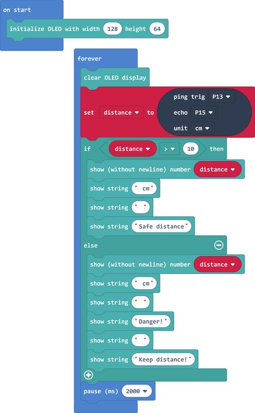
Instruction

                   Easy                              Funny                     Affordable

The Elecrow Starter kit for Micro:bit is designed for people who are at the doorstep of learning
electric modules and programming knowledge and bring numerous creative possibilities for
you to dig out and help you enter a wonderful electronic world. This kit includes more than 20
modules like the buzzer, light sensor, servo, ultrasonic ranging sensor, and OLED, etc. The kit
also provides you plenty of fun experiments so you can learn how the electric modules work
and use it to build innovative works and plan out unique projects. In addition, the kit also
focuses on stimulating children's creativity so that they can continue to move forward rather
than stagnate after completing their work. We never allow complicated jumpers to prevent
children from learning about the electronic world and programming hobbies and interests,
and we vowed to change it. Therefore, we have equipped this starter kit for Micro:bit with our
plug-and-play crowtail series of electronic modules to make you realize the electronic works in
the mind quickly and easily.

                                                 1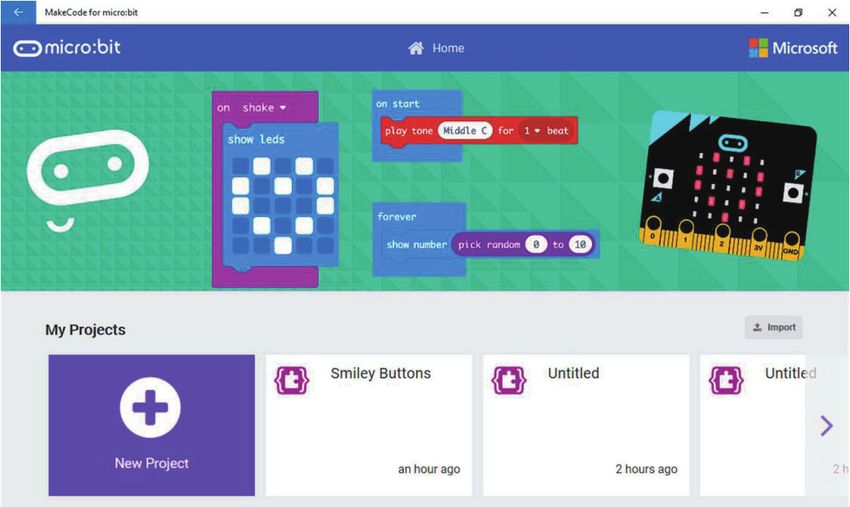
Get to know micro:bit
Micro:bit is a pocket-sized computer that lets you get creative with digital technology. You can
code, customize and control your micro:bit from anywhere! You can use your micro:bit for all
sorts of unique creations, from robots to musical instruments, the possibilities are infinite. The
micro:bit compatible with a number of online code editors across a number of different
languages, such as Blocks, JavaScript, Python, Scratch, and etc. This guide will focus on
Makecode, a block or JavaScript-based environment developed by Microsoft.
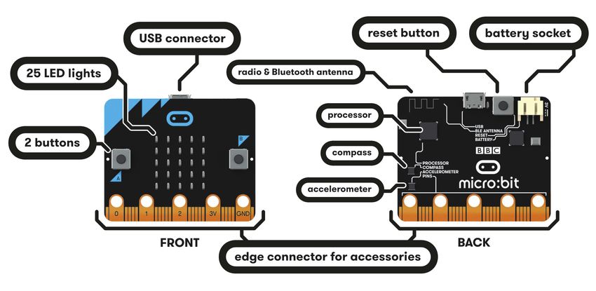
Components on the board
Edge "Pins": The gold tabs at the bottom of the board are
for hooking up external components. The tabs with larger
holes can be easily used with alligator clips to prototype
quickly!
LED Array: The micro:bit has 25 individually-programmable
LEDs, these 5x5 red LEDs form a very small section of a screen,
and display information like words, numbers, and pictures
through a combination of ON and OFF LEDs.
2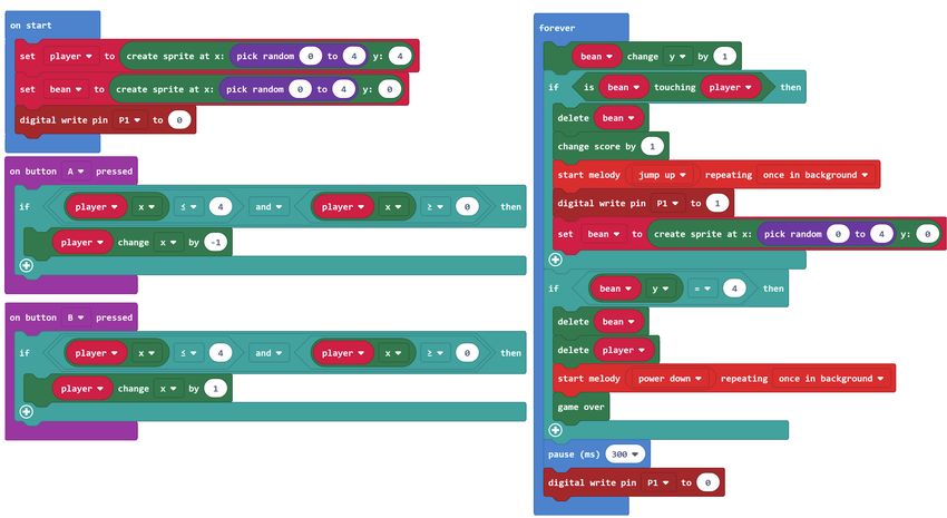
A/B Buttons: There are two buttons on the front of the
micro:bit - button A and button B, you can detect when these
buttons are pressed, allowing you to trigger code on the
device. You can detect events such as a single press, a double
press, and a long press by programming.

Light Sensor: The LED screen works as a basic light sensor by
reversing the LEDs of the screen to become an input which
allows you to detect the ambient light.

Compass: The compass detects the earth’ s magnetic field,
allowing you to detect which direction the micro:bit is facing.
The compass has to be calibrated before it can be used.
Calibrating the compass ensures the compass results are
accurate.

Accelerometer: The accelerometer measures
the acceleration of your micro:bit, it can track
motions like tilt, free fall and shake.

                                          Temperature Sensor: The Microcontroller doubles
                                          as a temperature sensor! The temperature sensor
                                          transforms the temperature in the ambient
                           5
                                          environment into digital signals that can be read by
                                          the micro:bit for calculating the current tempera-
                                          ture of the device.

                                              3
Radio: The radio feature allows you         Bluetooth: The Bluetooth Low Energy antenna
 to communicate wirelessly                   allows the micro:bit to send and receive Bluetooth
 between two or more micro:bits.             signals, you can wirelessly communicate between
                                             micro:bit and phones, PCs, or tablets. You need to
                                             pair your micro:bit with another device before using
                                             the Bluetooth antenna.

Quick start
  Step 1. Connect it
Connect the micro:bit with your computer via a USB cable, then your micro:bit will show up on
your computer as a drive called “MICROBIT”.

  Step 2. Program it
Write your micro:bit code by using the official online editor https://makecode.microbit.org/

                                                  4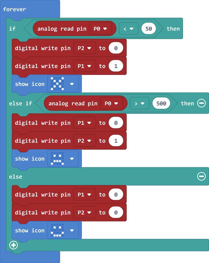
The left part is a simulator, which will simulate the work of micro:bit after finishing the
program. The middle part is our command area, there are various program blocks we need.
The rightmost area is the script area, you can drag and drop instructions into this area to form
your program. Drag and drop some blocks and try your program out in the Simulator in the
Makecode Editor, the example below shows you how to program a smiley face.
 Step 2-1. Select “on start” block in the command area, and drag it out to place it in the script
 area.

 Step 2-2. Drag out the “show icon” block and place it inside the “on start” block.

 Step 2-3. Pick a name for your program, We’ll name this project as “Smile Face”.

                    4                       3

                                                 5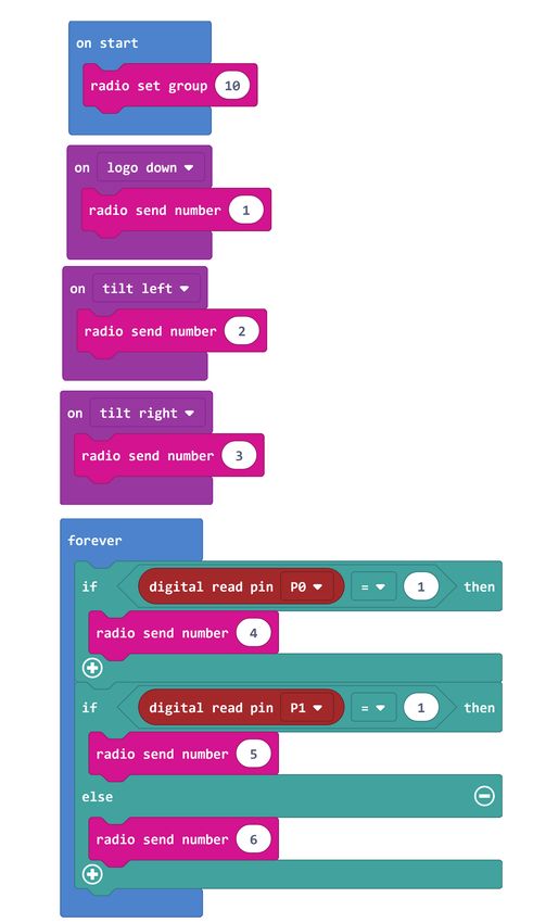
Step 2-4. Download the code
Click the Download button in the editor, And then it will download a “hex” file that your
micro:bit can read. Once the hex file has downloaded, copy it into your micro:bit like copying
a file into a USB drive.

  Step 3. Play
The micro:bit will pause and the yellow LED on the back of the micro:bit will blink while your
code is programmed, the code will run automatically once it’s finished. Then look at your
micro:bit, the screen will show a smiley face.

  Note: The micro:bit drive will automatically eject and come back each time you program it,
  but your hex file will be gone. It can only receive hex files and won’t store anything else.

APP for Micro:bit
There is no wire needed if you use Bluetooth to send the
code to your micro:bit from your mobile device. What
you need to do is to make sure your micro:bit is powered
up and within easy reach of the phone or tablet while
running the App. There are two types of APPs available
for micro:bit which are based on Microsoft Makecode
languages and Javascript: respectively micro:bit
companion app and Windows 10 APP.

The micro:bit app is the essential companion to the BBC
micro:bit, available for iOS and Android. Download the
official micro:bit app for Android or iOS from the app
store, the app contains handy instructions on how to
pair your micro:bit with the app.

The Windows 10 APP has a few extra features over the editor at makecode.microbit.org that
will work on micro:bits with up-to-data interface firmware: automatically program your
micro:bit over USB, without needing to drag-and-drop the file onto the micro:bit drive;
directly read serial data from your micro:bit for data logging and other fun experiments.

                                                 6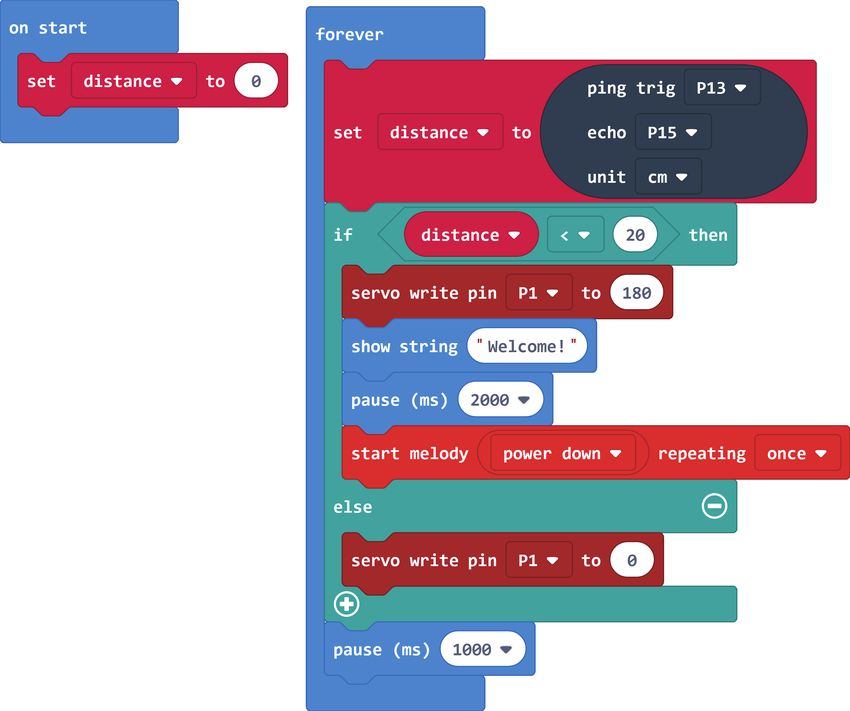
Modules list
  Crowtail-Base Shield for Micro:bit x1          Crowtail-Ultrasonic Ranging Sensor x1
  Crowtail-LED(Yellow)x1                         Crowtail-Linear Potentiometer x1
  Crowtail-LED(Green)x1                          Crowtail-Temperature&Humidity Sensor x1
  Crowtail-Buzzer x1                             Crowtail-Relay x1
  Crowtail-Switch x1                             Crowtail-9G Servo x1
  Crowtail-Touch Sensor x1                       Crowtail-RTC x1
  Crowtail-Collision Sensor x1                   Crowtail-OLED x1
  Crowtail-Light Sensor x1                       Crowtail-IR Receiver x1
  Crowtail-Moisture Sensor x1                    Infrared Remote Control x1
  Crowtail-PIR Motion Sensor x1                  DC motor x1

What is Crowtail
Welcome to the world of Crowtail! Crowtail is a modular, ready-to-use toolset, it takes a
building block approach to assemble electronics. It simplifies and condenses the learning
process significantly. In our Crowtail repository, there are over 150 Crowtail modules and
Crowtail shields!

The Crowtail products are basic-functional modules that consist of a Base Shield and various
modules with standardized connectors, each Crowtail module has its specific functions, such
as light sensing and temperature sensing. It will satisfy all you need for your project!

Crowtail is a series of products that we made to solve the messy jumper when connecting
electronic circuits. It consists of a Base Shield and some basic Crowtail modules, which help
you create small, simple, and easy-to-assemble circuits. In other words, when you use Crowtail,
your electronic project will not be messy wiring. Instead, it will be simple and easy to manage
an electronic project!

Crowtail-Base shield for Micro:bit
The Crowtail-Base shield for Micro:bit is the core part of this
kit, it acts as a bridge between Micro:bit board and Crowtail
modules. You can plug and then play with Crowtail
modules and micro:bit through this base shield, which
allows you to create more interesting and innovative works
with micro:bit. This shield integrated 6 crowtail connectors
and 2 crowtail UART/I2C connectors onboard. So you can
use plenty of crowtail sensors. All you need to know is that
there is no need for any soldering or jump wire about
Crowtail.
In addition, there is a power port, from which you can draw 3.3V/5V/12V three voltages! This
means that when you use a module such as a motor, you no longer need an external drive!

                                                  7
Note: When you connect a high-power device, such as a motor, you need to connect a 12V
power supply to the board.
Crowtail – Modules
We've made more than 100 kinds of electronic modules into Crowtail modules. They include a
variety of sensors, displays, inputs and outputs modules, communication types include I2C,
UART, digital or analog, which aim to provide more options to fully meet all needs for your
electronic projects! All modules can be used by simply connecting them to the Crowtail- Base
shield for Micro:bit with Crowtail cable, which is a huge improvement over the previously
troublesome jumper connections.
Exciting experiments
Experiment 1 – Blinking an LED
Instruction
Electric lights are ubiquitous in our daily life which we can't even leave. It was the invention of
the electric light that marked the human society's entry into the electric era, and made people
welcome the light in the dark night. Here, we will learn how to use the LED and control it’s on
and off.
Target
Learn how the LED work and use it to make a blinking light.
Learn how to run the code forever.
Learn how to output logic high and low signals.
Learn how to pause the code.
Required Parts
Micro:bit x1 Crowtail-Cable x1
Crowtail-Base shield for Micro:bit x1 USB cable x1
Crowtail-LED(Green)x1
Hardware learning and connection
LED is the best choice to help you learn I/O pins. What you need to do
is connecting the LED module to the port of the base shield, then
download the program to the Micro:bit. Besides the very basic usage,
you can make the LED blink with the frequency you want, or adjust
the brightness with PWM. Actually, LED is the most popular used for
human interface.
8Connect Crowtail-LED to P0 port of Crowtail-Base shield for Micro:bit. The hardware connections
are as follows:
Programming and note
Forever: The forever block is a block that loops
any other command blocks inserted into it over
and over again. It starts from the top and executes
your code in order by working its way to the
bottom and then starts from the top again.
Digital write: The digital write block enables
you to turn a pin on or off. There is a dropdown
option for you to choose which pin you want to
control, and it accepts a variable as the pins state.
You could use 1 as on and 0 as off. If you
prefer, you can also use Boolean states of true and false , but we will use 0 and 1 as our
standard throughout this guide.
Pause: If you were to just turn pins on and off with the digital write block without a pause,
the LED would blink really, really fast. The pause block enables you to slow the micro:bit
down and lets you control the timing of things happening. It accepts a number or variable as
the number of milliseconds you want the micro:bit to pause. Think of this block as a stoplight
for your code!
Download the program to micro:bit to see what happens.
Result
You will see the LED blink on and off at 2 seconds interval. If it doesn’t, make
sure you have connected the LED to correctly port.
Just like the lights at home, can we add a switch to control the lights on and off at any
time?
9Experiment 2 – Switch light
Instruction
Congratulations, you have mastered the method of controlling the LED on and off. But just like
the lights at home, can we add a switch to control the lights on and off at any time? Of course,
in this experiment, we will use our switch module to control the lights anytime and anywhere.
Target
Learn how the switch work and use it to make a switch light with LED.
Learn how to use the if/else logic statement.
Learn how to read the state from the digital module.
Required Parts
Micro:bit x1 Crowtail-Switch x1
Crowtail-Base shield for Micro:bit x1 Crowtail-Cable x2
Crowtail-LED(Green)x1 USB cable x1
Hardware learning and connection
The Crowtail- Switch is a Latching switch. When the switch is pressed for the
first time, the switch maintains current regulation and the button outputs a
HIGH signal in the self-locking state. When the switch is pressed for a second
time, the switch button pops up and the switch turns off and then outputs a
LOW signal. In fact, it is very similar to the button, except that the switch has a
self-locking function so that it can output logic high level signal without
pressing it all the time.
Connect Crowtail-Switch and Crowtail-LED to P0 and P1 ports of Crowtail-Base shield for
Micro:bit. The hardware connections are as follows:
10Programming and note
Digital Read: Just like the way digital write block turns a pin on (1) or off (0), the digital read
block check at the state of a pin, which is either HIGH (1) or LOW (0). In this case, we can detect if
the switch is pressed or not by using this block.
If/else: The if/else block is a logical structure. If the logical statement that is attached to it
(switchState=1) is true, then it will execute the code blocks inside of the if. If that statement is
false, it will execute the else blocks. In this case, if the statement is true(the value is digital read
from P0 port equal to 1), then turn on the LED on pin 1; else, turn off the LED on P1.
Download the program to micro:bit to see what happens.
Result
When you press the switch, the LED lights up, and when you press the switch
a second time, the LED turns off.
Do you have this experience? whenever you go up the stairs at night, the lights will
light up in front of you. Can we make such a lamp?
Experiment 3 – Micro:bit singer
Instruction
Do you like music? Have you ever dreamed of becoming a singer? The power of music is really
great, it can make people happy physically and mentally. In this experiment, we will make the
micro:bit to be a “singer”, let’s see how to do it!
11Target
Learn how the buzzer work and use it to play songs.
Learn how to run the code once at the beginning of the program.
Required Parts
Micro:bit x1 Crowtail-Cable x1
Crowtail-Base shield for Micro:bit x1 USB cable x1
Crowtail-Buzzer x1
Hardware learning and connection
The buzzer module is used for making sound in your project. It makes a
sound when activated by a logic HIGH signal. Connect the buzzer to any
port of Crowtail- Base shield for Micro:bit, you can easily make it sound with
setting the related port to logic HIGH. The buzzer module can also be
connected to an analog pulse-width modulation(PWM) output to generate
various tones, which means you can use it to create your own melody!
Connect Crowtail-Buzzer to P0 port of Crowtail-Base shield for Micro:bit. The hardware
connections are as follows:
Programming and note
Start melody repeating: The Start Melody Repeating block eliminates all of the frustra-
tion from getting music from a microcontroller. It is as simple as selecting one of the many
songs that were pre-programmed into MakeCode and repeating it as many times as possible!
Note that: There’s no other to run while the melody is playing. Which is called "blocking" code
and must be Considered in your program.
12On start: Different from forever block that loops your code forever, The On start block
is a block of code that only runs once at the very beginning of your program. In this case, we
use it to set the melody to play once.
Download the program to micro:bit to see what happens.
Result
Once you upload the program to micro:bit, you can hear the buzzer playing
the “dadadum” melody once and then stop.
How to make a buzzer play multiple melodies and control the previous and next song
by pressing a button?
Experiment 4 – Do not touch
Instruction
There are so many dangerous areas that we can’t touch with our hands directly, otherwise, we
may be in danger. For example, we can't touch the power socket with our hands because the
danger of electric shock! Therefore, this time we will make a touch alarm, put this alarm in a
simulated danger area, and when someone touches it, make the buzzer shout loudly so that
they will never touch this area again!
Note: Do not use it in a truly dangerous area, it can be dangerous!
Target
Learn how the touch sensor work and use it to make a touch alarm with buzzer.
Required Parts
Micro:bit x1 Crowtail-Buzzer x1
Crowtail-Base shield for Micro:bit x1 Crowtail-Cable x2
Crowtail-Touch Sensorx1 USB cable x1
Hardware learning and connection
The touch sensor can detect the human touch by sensing changes in
capacitance. When it detects a touch, it outputs a HIGH logic level signal.
Based on the touch IC TTP223-B, this module can detect human finger in
0~3mm, that is, you can place this sensor on a non-metallic surface such as
the glass or paper, with a thickness of less than 3MM, this would be useful for
applications that waterproof is needed, or you want to keep the buttons
secret.
13Connect Crowtail-Touch Sensor and Crowtail-Buzzer to P0 and P1 ports of Crowtail-Base shield
for Micro:bit. The hardware connections are as follows:
Programming and note
Digital Write:
Different from the last experiment, this time we will use digital write block to set the
buzzer 1(on), which can make the buzzer make a big bee noise to prevent touching. The
buzzer will stop sounding until you stop touching.
Download the program to micro:bit to see what happens.
Result
If you put your hand on the touch sensor, the buzzer will make a large beep
to prevent touch. The buzzer will not stop sounding until you remove your
hand from the touch sensor.
By learning this experiment, we know the touch sensor can sense our hand. So, if we
have many touch sensors and a buzzer, We can make a touch-type musical instrument
that allows us to play own melody?
14Experiment 5 – Collision check
Instruction
Do you know there is a collision sensor inside the car? It is used to detect collisions to make sure
the car can open airbag immediately and alarming after the impact. In this experiment, let's
make a collision detector to simply simulate the process of automobile collision detection.
Target
Learn how the collision sensor work and use it to make a collision detector with buzzer.
Required Parts
Micro:bit x1 Crowtail-LED(Yellow) x1
Crowtail-Base shield for Micro:bit x1 Crowtail-Cable x3
Crowtail-Collision Sensor x1 USB cable x1
Crowtail-Buzzer x1
Hardware learning and connection
This is a robot model car crashes or collision switch sensor module,
it usually outputs a logic HIGH signal, but when the sensor crash
something such as the wall, the on-board switch will be pressed,
and the module outputs a logic LOW signal. This module can be
installed into any mobile platform to achieve collision detection
function via 4 pin sensor cable and Micro:bit sensor expansion
board connector.
Connect the Crowtail-Collision Sensor, Crowtail-LED and Crowtail-Buzzer to P1, P0 and P2 ports
of Crowtail-Base shield for Micro:bit. The hardware connections are as follows:
15Programming and note
If/else: The If/else block is a logical structure. If the logical statement that is attached to it
(digital read P1 = 0) is true, then it will execute the code blocks inside of the if. If that
statement is false, it will execute the else blocks. In this case, if the statement is true(the
value is digital read from P1 port equal to 0, note that it will output a logic LOW signal when
the collision sensor is crashed), then turn on the LED and buzzer on P0 and P2; else, turn off
the LED and buzzer on P0 and P2.
Digital Write: There are two modules we need to use the digital write block to set they
output 1(logic HIGH signal) or 0(logic LOW signal). Here, we set the LED and buzzer output to
1 when the collision sensor detect a collision, otherwise, set it to 0.
Download the program to micro:bit to see what happens.
Result
When the on-board switch of the collision sensor is pressed, LED will light on
and the buzzer will make a big beep noise to remind collision to occur,
otherwise, LED will light off and buzzer stop work.
The car can detect a collision, but how the car detects the obstacle to prevent a crash?
16Experiment 6 – Intelligent corridor lights
Instruction
You must have a lot of questions if pay attention to the various phenomena of daily life, such as
corridor lights? How does it work? How did it automatically turn on the lights when we went
up the stairs? With these questions in mind, let's start our sixth experiment: intelligent corridor
lights.
Target
Learn how the light sensor works and use it to make an intelligent corridor light with LED.
Learn how to read the values from an analog module.
Required Parts
Micro:bit x1 Crowtail-LED(Green) x1
Crowtail-Base shield for Micro:bit x1 Crowtail-Cable x2
Crowtail-Light Sensor x1 USB cable x1
Hardware learning and connection
The Light sensor module uses the GL5516 photoresistor to detect the
light intensity of the environment. The resistance of the sensor decreases
when the light intensity of the environment increases. The chip LMV358
is used as a voltage follower to enable you to get accurate data.
This module outputs an analog signal that shows the light intensity. It
can be used in many occasions, such as Intelligent street light, intelligent
corridor light, etc.
Connect Crowtail-Light Sensor and Crowtail-LED to P0 and P1 ports of Crowtail-Base shield for
Micro:bit. The hardware connections are as follows:
17Programming and note
Analog Read: Micro:bit uses an analog read block to read the value as a 10-digit number
that ranges from 0 to 1023. The analog read block is a value based block, Which means
that you have to insert it into a block with a matching shape. In this case, we use this value
and compare it with the value( It indicates that the brightness is bright and we don’t need
to turn on the LED when threshold we set is larger than this value; when it is less than this
value, it indicates that the brightness is dark and we need to turn on the LED).
Download the program to micro:bit to see what happens.
Result
The LED will not light up during the day (in a bright environment). And when
the daylight gradually dims into the night, the LED will light up automatically.
If the LED does not change, try to adjust the threshold you set.
Do you have plants in your home? Did you know that a plant needs light to grow? If
there is no enough light, plants will wither. Let's protect them and think about how to
use this light sensor to solve this problem.
18Experiment 7 – Plant soil moisture detection
Instruction
People need water to survive, so do plants. Soil moisture indicates the moisture in the soil. As
long as the soil moisture value is suitable for the plant, the plant can get water from the soil.
Therefore, in this experiment, we will make a plant soil moisture detector to ensure that our
plants can get enough water and grow.
Target
Learn how moisture sensor work and use it to make a moisture detector with LED and buzzer.
Learn how to draw icon on Micro: bit's matrix LEDs.
Learn how to use if/else if/else statement.
Required Parts
Micro:bit x1 Crowtail-Buzzer x1
Crowtail-Base shield for Micro:bit x1 Crowtail-Cable x3
Crowtail-Moisture Sensor x1 USB cable x1
Crowtail-LED(Yellow) x1
Hardware learning and connection
This Moisture sensor can be used to detect
the moisture of soil and thus to monitor if the
plants in your garden need some water.
This sensor uses the two probes to pass
eletricity through the soil, and then reads the resistance to get the moisture level. More water
makes the soil conduct electricity more easily(less resistance), while dry soil conducts electricity
poorly(more resistance). Compares to the other moistures sensor using the same moisture test
method, this module has super long legs, making it suitable for actual applications.
Connect Crowtail-Moisture Sensor, Crowtail-Buzzer and Crowtail-LED to P0, P1 and P2 ports of
Crowtail-Base shield for Micro:bit. The hardware connections are as follows:
19Programming and note
Show Icon: We can use this show icon block
to draw icons on the Micro:bit’s matrix LEDs.
Many icons have already been created in this
block, so we just need to select the icon to be
drawn.
If/else if/else statement: If/else if/else is a
logical structure that is very similar to if/else.
Actually, it is derived from the if / else
structure. It can resolve judgments when there
are more than two cases. If the logical
statement that is attached to if(analog read
from P0 is less than 50) is true, then it will
execute the code blocks inside of the if . If the
logical statement that is attached to else if
(analog read from P0 is more than 500) is true,
then it will execute the code blocks inside of
the else if . Else(analog read from P0 is larger
than 50 and less than 500), it will execute the
else blocks.
Download the program to micro:bit to see what happens.
Result
When the soil moisture sensor is inserted into the dry soil, the buzzer will
beep and the X icon will be displayed on the micro: bit matrix LED; when it is
inserted into the Water-filled soil, the LED will light up and a sad icon will be
displayed on the micro: bit's matrix LED; when it is inserted into the moist
soil, the LED will not light up, the buzzer will not beep, and a happy icon will
be displayed on the micro: bit's matrix LED.
Can we make an automatic watering system for plants after detecting low soil moisture?
And how to make it?
20Experiment 8 – Intrusion alert
Instruction
Have you ever played any adventure games? They can always open the institutions when the
enemy enters their private territory. How does this work? In fact, this is the role of intrusion
alarms. Through this experiment, we will teach you how to make your own intrusion alarm, and
quickly put it in your private space to protect your own space!
Target
Learn how PIR motion sensor works and use it to make an intrusion alarm with buzzer.
Learn how to clear Micro:bit’s matrix LEDs.
Required Parts
Micro:bit x1 Crowtail-Buzzer x1
Crowtail-Base shield for Micro:bit x1 Crowtail-Cable x2
Crowtail-PIR Motion Sensor x1 USB cable x1
Hardware learning and connection
Crowtail- PIR Motion Sensor(Passive Infrared Sensor) can
detect infrared signals caused by motion. If the PIR sensor
notices the infrared energy, the motion detector will be
triggered and the sensor outputs HIGH on its SIG pin. The
detecting range can be adjusted by a potentiometer
soldered on its circuit board, the max detecting range of it
up to 6 meters. P0 is a port with pull-down, please do not connect PIR motion sensor to this
port! For the micro: bit, when the PIR module detects an object movement, it will change from
low level to high level and output high level continuously for 5 seconds, which means you don't
need to set extra delay.
Connect Crowtail-PIR Motion Sensor and Crowtail-Buzzer to P2 and P1 ports of Crowtail-Base
shield for Micro:bit. The hardware connections are as follows:
21Programming and note
If/else: In this case, when the value digital read from the PIR motion sensor is true(1), turn
on the buzzer and show an angry icon for 5 seconds, otherwise, clear the micro:bit’s matrix
LEDs and turn off the buzzer.
Clear screen: This clear screen block will clear all the information displayed on
micro:bit’s matrix LEDs when it runs. Here, we clear matrix LEDs when PIR motion sensor
does not detect the movement of Infrared energy.
Download the program to micro:bit to see what happens.
Result
Wave your hand in front of the PIR motion sensor, and you will see an angry
icon on the micro: bit matrix LED, and the buzzer will beep for 5 seconds. If
you stop any movement, the icon will no longer be displayed and the buzzer
will stop beeping.
What does infrared energy mean? Can PIR motion sensor detect your pet's movement?
22Experiment 9 – Make an adjustable table lamp
Instruction
The eye is a very important organ for us. We can see the colorful world by them. so protecting
eyes is very important to us! Reading in a too bright or too dark environment can cause
damage to our eyes, so when we read a book, we must pay attention to the brightness of the
light to be appropriate. Maybe what we need at this time is a table lamp with adjustable
brightness, let's start to make it!
Target
Learn how linear potentiometer works and use it to make an adjustable table lamp with LED.
Learn how to change the brightness of the LED.
Learn how to create variables to store value.
Learn how to remap numbers from one range to another.
Required Parts
Micro:bit x1 Crowtail-LED(Green) x1
Crowtail-Base shield for Micro:bit x1 Crowtail-Cable x2
Crowtail-Linear Potentiometer x1 USB cable x1
Hardware learning and connection
The Crowtail- Linear Potentiometer module uses a
linear variable resistor with a maximum resistance of
10KΩ. When you move the slider from one side to the
other, its output voltage will range from 0 V to the
VCC you applied. The panel mount design makes this
module easy to be installed in projects.
Connect Crowtail-Linear Potentiometer and Crowtail-LED to P0, P1 ports of Crowtail-Base
shield for Micro:bit. The hardware connections are as follows:
23Programming and note
Set to: You can use this set to block to set the value for a variable that selected from a list
of the variables you create. You can create variables by click Variables→Make a Variable and
then naming it.
Analog write: Just like the analog read block, the analog write block deals with a
range of values, but instead of reading a pin as an input, the analog write block outputs
an analog value to a pin. In this case, we use this block to set the brightness of the LED, but
it could be a tone for a buzzer, a motor speed and etc.
Map: This is a mathematical method used to map values from one interval to values from
another interval.The mapped value range will be reduced or enlarged by a certain propor-
tion. Here we need to map the potentiometerValue(value between 0 and 1023) to value
(between 0 and 255) and write it to P1 port. For example, if the value of potentiometerVal-
ue is 240, then after mapping, we get the value is 60 and write it to port P1. The reason we
use this mapping function is that the LED has a brightness level of 256 (0-255). When the
brightness level is greater than 255, the brightness of the LED will not change.
Download the program to micro:bit to see what happens.
Result
Toggle the potentiometer and you will find that the LED light will become
brighter or dimmer depending on the position of the potentiometer. When
you turn the potentiometer to the far left, the LED light goes out, and when
you turn to the right, the LED light is the brightest.
Since the brightness of the lamp can be adjusted in this way, is the sound volume of the
stereo adjusted in this way?
24Experiment 10 – Automatic control
Instruction
How do we safely use high-power appliances, do you know how to control the elevator? In fact,
it needs an automatic control system, in which the relay plays an important role in helping us.
This system guarantees our electricity safety by controlling large currents with small currents.
In this lab, we will learn how to use relays to build an automatic control system for controlling
motors.
Note: Do not connect high-power electrical appliances, otherwise accidents will occur due to
improper use!
Target
Learn how relay works and use it to control the DC motor with switch.
Required Parts
Micro:bit x1 DC Motor x1
Crowtail-Base shield for Micro:bit x1 USB cable x1
Crowtail-Relay x1 Jumper Wire x1
Crowtail-Switch x1
Crowtail-Cable x2
Hardware learning and connection
The Relay is the most commonly used module in some actual applications such as home
automation, and sometimes you need to control large current such as the air conditioning/water
heater. That is what this Large Current Relay Module can help with.
The connector of the relay module has three sockets: common (COM), normally closed (NC), and
normally open (NO). COM: common pin. NC (Normally Closed): the normally closed configuration
is used when you want the relay to be closed by default, meaning the current is flowing unless
you send a signal to the relay module to open the circuit and stop the current. NO (Normally
Open): the relay is always open, so the circuit is broken unless you send a signal to close the
circuit.
This Large Current Relay Module is a high-quality Single Pole Double Throw Relay(SPST). When
the relay not triggered, the 2 outputs are disconnected; when the relay triggered(Logic Low), the
2 outputs connected, the max current can be up to 30A@240VAC or 30A@30VDC, which would
be enough for most of the home appliances.
25Connect Crowtail-Switch and Crowtail-Relay to P1 and P8 ports of Crowtail-Base shield for
Micro:bit. Loosen the screws of the relay, connect one end of the jumper to the 3V3 port of the
Base Shield and the other end of the jumper to the COM port of the Relay. Connect the two
wires of the motor to the NO port of the relay and the GND port of the Base Shield. Note that
the power consumed by the motor is large, you need to connect a 12V power supply to the
Crowtail-Base shield for Micro:bit. The hardware connections are as follows:
Programming and note
Digital write: When the switch is detected
to open, we use the digital write module
to turn on the relay (1), and then the battery
box power can flow through the DC motor
so that the battery box and the DC motor
could form a closed circuit, then DC motor
starts to work. When the switch is detected
to be closed (0), the relay will close, then the
closed circuit will be blocked, so the DC motor will no longer work.
Download the program to micro:bit to see what happens.
Result
When the switch is pressed for the first time, the relay will open and the DC
motor will start working. When the switch is pressed a second time, the relay
will close and the DC motor will stop working.
What role do relay plays in automatic control systems? What are the appliances that
also use relays in our lives?
26Experiment 11 – Automatic door
Instruction
It’s so convenient when we enter and exit the gate of the community, that the door will open
and closes automatically after we press the switch of the gate. How about making a mini
automatic door?
Target
Learn how servo work and use it to make a mini automatic door with touch sensor.
Learn how to rotate the servo.
Required Parts
Micro:bit x1 Crowtail-Touch Sensor x1
Crowtail-Base shield for Micro:bit x1 Crowtail-Cable x1
Crowtail-9G Servo x1 USB cable x1
Hardware learning and connection
Tower Pro SG90 is a high quality, low-cost servo for all
your mechatronic needs. It comes with a 4-pin power
and control cable, mounting hardware. Servo is used in
many intelligent situations, such as automatic doors,
robots, aerial models, etc.
It can be said that the servo is almost an indispensable
module in the field of intelligent control. Have you
thought about adding a rotatable part to your smart product, such as automation field,
robot's head and hand. Note: For all experiments using the servo module, you need to connect
a 12V power supply for the Crowtail-Base shield for Microbit.
Connect Crowtail-9G Servo and Crowtail-Touch Sensor to P1 and P0 ports of Crowtail-Base
shield for Micro:bit. The hardware connections are as follows:
27Programming and note
Servo write: Use this servo write block to write a value to the servo on the specified pin
and control the shaft. This function will move the shaft of a standard servo(Crowtail-9G
Servo) to the specified angle, or set the speed of a continuous rotation servo (0 specifies full
speed in one direction, 180 specifies full speed in the other, and approximately 90 specifies
no movement). In this case, we will move the servo’s shaft to 180 degrees and 0 degrees
these two specified angles.
Pause: After we moved the servo's shaft to 180 degrees (opening the door), we used a
"pause" block to pause the code so that the door would not close immediately and there
was enough time to enter or exit the door.
Download the program to micro:bit to see what happens.
Result
Press the touch sensor, the shaft of the servo will move to 180 degrees. After
two seconds, if the touch sensor is not touched, the servo’ s shaft will move
back to 0 degrees.
How to make automatic doors smarter? When we stand in front of the door, how do
we make it open automatically without any keys or switches?
28Experiment 12 – Weather station
Instruction
The changing weather is so annoying, I even got a cold because of it! No, I have to think of a
way to remind myself of changes in the weather at all times. I have to pay attention to keep
warm and never catch a cold again. Less gossip, let’s make a weather station to ensure we can
obtain temperature and humidity anytime and anywhere to solve this problem!
Target
Learn how Temperature&Humidity sensor work and use it to make a weather station.
Learn how to add an extension package.
Learn how to use two onboard buttons of micro:bit.
Required Parts
Micro:bit x1 Crowtail-Cable x1
Crowtail-Base shield for Micro:bit x1 USB cable x1
Crowtail-Temperature&Humidity Sensor x1
Hardware learning and connection
This module can help you detect the temperature and
humidity of the environment of your house. The
module contains a DHT11 temperature & humidity
sensor that is a complex sensor with a calibrated digital
signal out. It uses digital module acquisition technology
and temperature&humidity sensor technology. The
sensor consists of a resistance type moisture element
and an NTC temperature measuring element. Because of the single-wire serial interface, it is
easy to use the module.
Connect Crowtail-Temperature&Humidity Sensor to P0 port of Crowtail-Base shield for
Micro:bit. The hardware connections are as follows:
29Programming and note
To using the Crowtail-Temperature&Humidity Sensor, we need to add the extension package.
Follow the steps below to add extension package:
Step 1: Click on the Extensions Step 2: Enter the address in the search bar and search:
https://github.com/Tinkertanker/pxt-iot-environment-kit
Step 3: You will view the search Step 4: Then you can see the extensions package you added
results andclick on it. in Makecode and click to use the DHT11 block.
On button pressed: Start an event handler (part of the program that will run when
something happens, like when a button is pressed). This handler works when button A or B
is pressed, or A and B together. When you are using this function in a web browser, click the
buttons on the screen instead of the ones on the micro:bit. In this experiment, when button
A is pressed, show the temperature on micro:bit’s matrix LEDs; when button B is pressed,
show humidity on micro:bit’s matrix LEDs.
Value of dht11...at pin...: Use this block in the extension package we added to set the pin
of Crowtail-Temperature&Humidity Sensor and get data from it. Available data includes
Fahrenheit, Celsius and Humidity. In here, we get Celsius and Humidity from the sensor.
30Download the program to micro:bit to see what happens.
Result
When you press button A on the micro: bit, the matrix LEDs will show you the
current temperature. When you press button B on the micro: bit, the matrix
LEDs will show you the current humidity.
How to build a more comprehensive weather station so that we can get air quality,
temperature, humidity, ultraviolet information and more?
Experiment 13 – Ultrasonic ranging smart door
Instruction
Do you remember the thinking problem in experiment 11 ? Did you find the answer? If you
don't, rest assured that we will lead you to build such a smart, automatic door in this experi-
ment. The only difference is that in this section we will use delicate and magical ultrasonic
sensors.
Target
Learn how ultrasonic ranging sensor works and use it to make a smart door with servo and buzzer.
Learn how to get the distance from the ultrasonic ranging sensor.
Required Parts
Micro:bit x1 Crowtail-Buzzer x1
Crowtail-Base shield for Micro:bit x1 Crowtail-Cable x2
Crowtail-Ultrasonic Ranging Sensor x1 USB cable x1
Crowtail-9G Servo x1
Hardware learning and connection
This HC-SR04 has stable performance and high ranging
accuracy. The process of ultrasonic ranging: Ultrasonic pulses
travel outward until they encounter an object, The object
causes the wave to be reflected back towards the unit. The
ultrasonic receiver would detect the reflected wave and stop
the timer. Now read the time of the counter, which is the
ultrasonic propagation time in the air. According to the formula: Distance = ECHO high level
time X ultrasonic velocity (Speed of Sound in air 340m/sec) / 2, you can calculate the distance
to the obstacle.
31Connect Crowtail-Ultrasonic Ranging Sensor, Crowtail-Buzzer and Crowtail-9G Servo to P13&P15,
P0 and P1 ports of Crowtail-Base shield for Micro:bit. Note: You need to connect 12V power supply
for the Crowtail-Base shield for Micro:bit. The hardware connections are as follows:
Programming and note
Just as Crowtail-Temperature&Humidity Sensor, we need to add the extension package for
Crowtail-Ultrasonic Ranging Sensor before we use it. Follow the steps below to add extension
package of ultrasonic ranging sensor:
Step 1: Click on the Extensions, then search “sonar” in the
search bar.
Step 2: Add sonar package to your Makecode and you
can see it.
32Ping trig…echo…unit: This block is inside
the sonar package we added. We can use
this block to get the time, distance in cm and
distance in inches detected from the
ultrasonic ranging sensor. In this experiment,
we set the trig pin and echo pin of the sensor
are P13 and P15 port of micro:bit. And the
data we want to get is the distance in cm.
Start melody repeating: We use the Start
Melody Repeat block to play a melody to
remind the door is about to close, please be
careful! When the melody ends, the door
begins to close.
Download the program to micro:bit to see what happens.
Result
When the distance detected by the ultrasonic sensor is less than 20 cm, open
the door (the servo’ s shaft rotates 180 degrees), and the matrix LEDs of the
micro: bit will display "Welcome". After 2 seconds, the buzzer will play a melody
to warn that the door is about to close. Then, when the distance detected by
the ultrasonic sensor more than 20 cm, the door start closing (the servo’ s
shaft rotates 0 degrees).
How to apply ultrasonic ranging sensors to the car to make the car have an obstacle
avoidance function?
Experiment 14 – Make an accurate clock
Instruction
Have you ever been late for school because you forgot to set the alarm clock? This is really
embarrassing! Let's make an alarm clock with a RTC module together today, and say goodbye
to being late!
Target
Learn how RTC work and use it to make a clock with buzzer.
Learn how to set time for RTC.
33Required Parts
Micro:bit x1 Crowtail-Buzzer x1
Crowtail-Base shield for Micro:bit x1 Crowtail-Cable x2
Crowtail-RTC x1 USB cable x1
Hardware learning and connection
This tiny RTC module is based on the clock chip DS1307 which communi-
cates with microcontrollers with I2C protocol. The clock/calendar
provides seconds, minutes, hours, day, date, month and year information.
The end of the month date is automatically adjusted for months with
fewer than 31 days, including corrections for leap year. Besides, this
module is really low power consumption, it can serve you more than a month with a CR1220
battery.
Connect Crowtail-RTC and Crowtail-Buzzer to I2C and P0 port of Crowtail-Base shield for
Micro:bit. The hardware connections are as follows:
Programming and note
Before we using the RTC, we need to add an extension package for RTC(DS1307). Follow the
steps below to add an extension package of RTC.
Step1: Click on the Extensions, then search “ds1307” in the search bar.
OLED
Step2: Add the DS1397 package to your Makecode and
you can see it.
34Set date and time: We use this block to set the current date and time. In this case, we start
the time from the beginning of the program, so the time needs to be set exactly the same
as your local time, or you can set it faster because you need time to upload the program,
otherwise the clock may be inaccurate.
And: It is a logic and block. This combines two logical statements into one statement that
returns true when both of the other statements are true and only true. In this experiment,
when hour equal to 7 and minute less than 2, then if run the code inside if statement.
Otherwise, the code inside if statement will not run.
Download the program to micro:bit to see what happens.
Result
After uploading the program, the buzzer will start playing music for 2 minutes.
Then, if you don't stop powering the micro: bit, the buzzer will play the
"alarm" for 2 minutes every day starting from 7 am.
Can you display the time on the micro: bit's matrix LEDs in the format we see every day?
Experiment 15 – Distance display
Instruction
It takes too much time to scroll the messages on the micro: bit's matrix LEDs, which makes
viewing very inconvenient. But don't worry, you will learn a better way to display messages or
data from this experiment. It does not require you to spend time waiting for the information to
scroll. You can see all the messages and data at a glance. This method is to use OLED for display.
35Target
Learn how OLED works and use it to make a monitor with ultrasonic ranging sensor to show
distance that detected by the ultrasonic ranging sensor.
Learn how to show number and string on OLED.
Required Parts
Micro:bit x1 Crowtail-OLED x1
Crowtail-Base shield for Micro:bit x1 Crowtail-Cable x2
Crowtail-Ultrasonic Ranging Sensor x1 USB cable x1
Hardware learning and connection
Crowtail- OLED is constructed from the 128 x 64 dot-matrix
OLED module. The display offers high brightness, self-emission,
high contrast ratio, slim/thin outline, wide viewing angle, wide
temperature range and low power consumption. You can almost
display anything with this OLED module, such as text and pictures!
This kind of OLED is very suitable to use in your project which needs
a small display to show data or pictures.
Connect Crowtail-Ultrasonic Ranging Sensor and Crowtail-OLED to P13&P15 and I2C ports of
Crowtail-Base shield for Micro:bit.The hardware connections are as follows:
Programming and note
We need to add two extensions package before we use OLED(SSD1306) and ultrasonic ranging
sensor, Follow the steps below to add extension packages of them.
Step1: Click on the Extensions, then search “OLED” and “sonar” in the search bar.
sonar OLED
36Step2: Add sonar and OLED packages to your Makecode and you can see it.
Initialize OLED with width…height…:
This block is used to set up the OLED display and is
ready for micro: bit use. In order to use our 128 x
64 dot matrix OLED module, we need to initialize
the OLED according to the hardware, setting the
width to 128 dots and the height to 64 dots.
Clear OLED display: This block is used to clears the
OLED display. In this case, every time we cycle, we
will display on a clear OLED screen.
Show(without newline) number:Displays a
number on the OLED module without a newline.
Note that the next line(“ cm”) is on the same line as
this block display.
Show string: Displays a string on the OLED
module with a newline. If nothing is filled in this
block, nothing will be displayed. This can be used
for a blank line.
37Download the program to micro:bit and see what happens.
Result
When the distance detected by the ultrasonic ranging sensor is less than 10
cm, the distance and warning( “Danger!” and “Keep distance!” ) will be
displayed on OLED. Otherwise, the distance and Security Information( “Safe
distance” ) will be displayed on OLED.
Can OLED be used to make a more comprehensive display, showing all the data and
information we need on the OLED, such as time, light, temperature and humidity?
Experiment 16 – Wireless communication
Instruction
Wireless communications are everywhere in our daily life, such as mobile phones we most
often see and use. Wireless communication brings us a lot of conveniences. It enables us to
communicate with each other even thousands of miles apart. Thanks to the radio/Bluetooth
module on the micro: bit board, wireless communication can also be achieved between our
two micro: bits or communicate with the phone.
Target
Learn how radio work on micro:bit and use it to communicate between 2 micro:bits.
Learn how to send and receive numbers between 2 micro:bits.
Required Parts
Micro:bit x2 Crowtail-Cable x1
Crowtail-Base shield for Micro:bit x2 USB cable x1
Crowtail-Buzzer x1
Hardware learning and connection
Micro: bit has two wireless communication methods, one is radio communication and the other
is Bluetooth communication. These two hardware modules are embedded in the upper left
position behind the micro: bit, as shown in the figure. In this experiment, we will learn the
standard radio on micro:bit which allows you to communicate between two or more micro:bits.
38Connect Crowtail-Buzzer to P0 port of Crowtail-Base shield for Micro:bit(named bit1). Plug another
micro:bit into Crowtail-Base shield for Micro:bit(named bit2, if you don’t have two Crowtail-Base
shield for Micro:bit, you don’t have to plug this micro:bit into Crowtail-Base shield for Micro:bit).
The hardware connections are as follows:
Programming and note
Send_code:
Receiver_code:
39Radio set group: Make a program have the group ID you tell it for sending and receiving with
radio. A group is like a cable channel (a micro:bit can only send or receive in one group at a
time). A group ID is like the cable channel number. If you do not tell your program which
group ID to use with this function, it will figure out its own group ID by itself. If you load the
very same program onto two different micro:bits, they will be able to talk to each other
because they will have the same group ID. In this experiment, we set the group of two micro:
bits to 1 so that they can communicate with each other.
Radio send number: This block is to broadcast a number to other micro:bits connected via
radio. You need to enter a parameter for this block which is the number you want to send.
On radio received receivedNumber: Run part of a program when the micro:bit receives a
number over the radio. “receivedNumber” is a parameter, it’s the number that was sent in this
packet or 0 if this packet did not contain a number. If the number received by bit1 (receiv-
er_code) is 3, the code inside the if statement of bit1 will be run. If the number received by
bit2 (send_code) is 4, the code inside the if statement of bit2 will be run.
Download the send_code program to bit2 and receiver_code program to bit1 and see
what happens.
Result
At first, the micro: bit matrix LEDs named bit2 will display a crying face, and
then the micro: bit of bit1 will immediately play a melody (comfort bit2), and
the crying face of bit2 will become a smiling face.
Does wireless communication require two or more micro:bits? Then if there are no two
micro:bits, can the micro: bits be controlled wirelessly? For example, the module is used
to wirelessly control the micro: bit.
Experiment 17 – Remotely control your micro:bit
Instruction
When you're too sleepy, you definitely don't want to get up from your bed and turn off the lights.
When you are busy with other things, you don't feel like being interrupted by knocking on the
door. Well, in this experiment we are ready to help you solve this problem. We will use the
remote control to remotely control these things, instead of having to leave for them.
40Target
Learn how IR receiver work and use it to control the LED with infrared remote control and
servo connected to micro:bit.
Learn how to detect the keys pressed by the infrared remote control.
Required Parts
Micro:bit x1 Crowtail-9G Servo x1
Crowtail-Base shield for Micro:bit x1 Crowtail-Cable x2
Crowtail-IR Receiver x1 Infrared Remote Control x1
Crowtail-LED(Green) x1 USB cable x1
Hardware learning and connection
The Crowtail- IR Receiver module uses the HS0038B which is miniaturized
receivers for infrared remote control systems and it is the standard IR
remote control receiver series, supporting all major transmission codes.
The IR detector has a demodulator inside that looks for modulated IR at
38 kHz, we can use our infrared remote control to control this module
well. The Infrared Receiver can receive signals well within 10 meters. If
more than 10 meters, the receiver may not get the signals.
Connect Crowtail-LED, Crowtail-IR Receiver and Crowtail-9G Servo to P0, P1 and P2 ports of
Crowtail-Base shield for Micro:bit. Note: You need to connect 12V power supply for Crowtail-Base
shield for Micro:bit. The hardware connections are as follows:
Programming and note
Before using the IR receiver, we need to add an extension package for this module. Follow the
steps below to add an extension package for it.
Step1: Click on the Extensions, then enter the following link
“https://github.com/osoyoo/OSOYOO_IR” in the search bar.
41Step2: Add the package to your Makecode and you can see it
Connect ir receiver to: This block is used to tell the micro:bit that which port the IR receiver is
connected.
On button pressed: This block is to detect whether the key on the infrared remote control is
pressed and which key is pressed. In this block, detecting which key was pressed is optional.
When the key we selected is pressed, the IR receiver will run the code we need to process when
the key is pressed.
Download the program to micro:bit to see what happens.
Result
When you press the "1" key on the controller, the LED will turn on; when you
press the "2" key, the LED will turn off. When you press the “3” key, the shaft
of the servo will rotate to 180 degrees(open door); when you press the “4”
key, the shaft of the servo will rotate to 0 degrees(close door).
Note: Before using the infrared remote control, please install a coin cell battery for it. The type
of the coin cell battery is CR2025.
Can we use remote knowledge to make a remote control car, and if so, what other
components and modules do we need?
42Experiment 18 – Smart music box
Instruction
Have you ever seen a robot that says hello when someone approaches? That is a very interesting
thing, so let's do a similar project in this lesson, put it in a box and make a fun and smart music
box!
Target
Use the modules and programming knowledge we have learned to make a smart music box.
Learn how to stop the buzzer melody.
Required Parts
Micro:bit x1 Crowtail-LED(Green) x1
Crowtail-Base shield for Micro:bit x1 Crowtail-LED(Yellow) x1
Crowtail-Ultrasonic Ranging Sensor x1 Crowtail-Cable x4
Crowtail-Buzzer x1 USB cable x1
Hardware learning and connection
Connect Crowtail-Ultrasonic Ranging Sensor to P13&P15
port of Crowtail-Base shield for Micro:bit. Connect
Crowtail-Buzzer, Crowtail-LED(Green) and Crowtail-LED
(Yellow) to P0, P1 and P2 ports of Crowtail-Base shield for
Micro:bit. The hardware connection are as follows:
Programming and note
Stop melody all: Stop playing a musical melody.
We can use this block to stop melodies that are
played either in the foreground or background. In
this case, if the value of dis more than 10, we use
this block to stop melody immediately.
Blocks overview
1. Add extension package for the ultrasonic
ranging sensor.
2. Set a variable named dis to store the distance detected by
the ultrasonic ranging sensor.
3. Read the distance in cm from ultrasonic and store in dis.
4. If the value of “dis” less than 10, show “heart” icon on
matrix LEDs, play a melody and turn two LEDs on.
43You can also read