VORTOK Coil

          The internationally
     proven and preferred method
    of repair for loose screwspikes
in wooden railway sleepers or dowels.
←
→
Page content transcription
If your browser does not render page correctly, please read the page content below
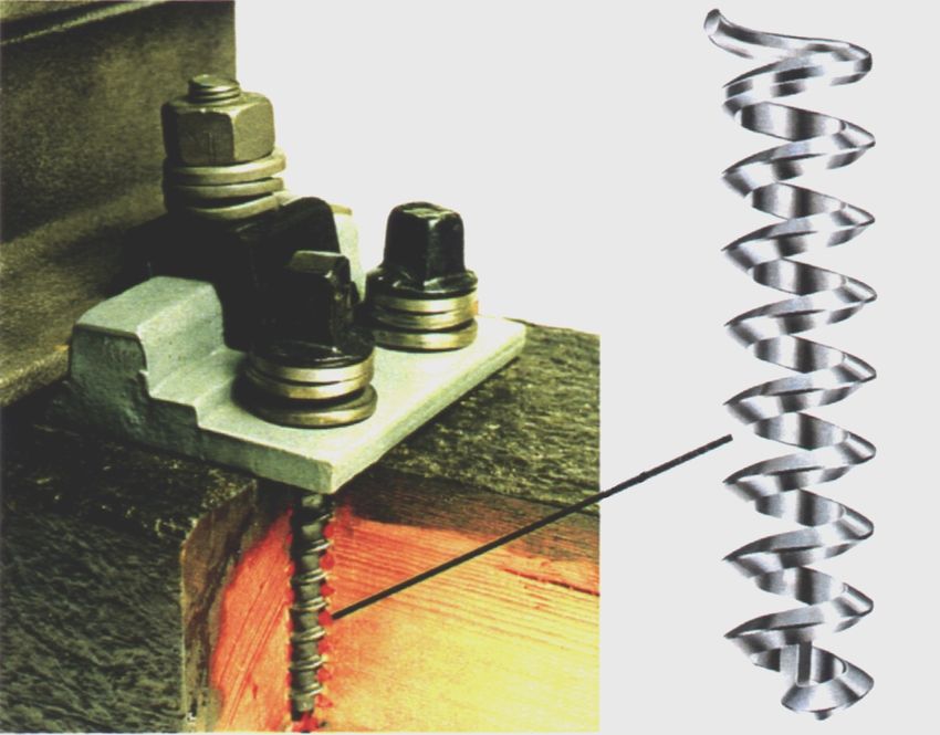
VORTOK Coil
The internationally
proven and preferred method
of repair for loose screwspikes
in wooden railway sleepers or dowels.VORTOK Coil
The internationally proven and preferred method
of repair for loose screwspikes
in wooden railway sleepers or dowels.
} Over 30,000,000 installed worldwide
} Delays sleeper replacement
} Simple, fast and economical to install
} Installed under traffic - No possession required
} Restores up to 90% of original pull-out strength and screw torque
} Improves track structure and gauge retention
} Unaffected by climatic or environmental conditions
} Existing screwspikes and fastenings can be re-usedInstalls in less than 1 minute
1. Remove screwspike
2. Wind VORTOK COIL onto
Insertion Tool
3. Wind Insertion Tool and
VORTOK COIL into hole - drive
fully home
4. Remove Insertion Tool
5. Reinsert original screwspike - if
hole is excessively worn, a second
VORTOK COIL may be inserted
over the top of the first
Fitted in less than one minute under traffic, without the
need to remove the baseplate, the Vortok Coil can restore
up to 90% of original pullout strength.
Over 30,000,000 supplied to nearly 35 countries worldwide
Approved by railway networks around the world
VORTOK
INTERNATIONAL
6 - 8 Haxter Close,
Belliver Industrial Estate,
Roborough,
Plymouth. Devon.
England. PL6 7DD
Tel: +44 (0) 1752 700601 • Fax +44 (0) 1752 702353
sales@vortok.co.uk • www.vortok.co.ukWhy use the VORTOK Coil? Loose screws in wooden sleepers have always challenged railway engineers. In the search for improved techniques, several methods have been trialed and adopted over the years. In 1988 Deutsche Bundesbahn undertook a comprehensive case study centering on their current method of a plastic plug and the then novel solution of the VORTOK coil. The tests concluded with Deutsche Bundesbahn recommending the immediate halting of the use of the plastic plug inserts and the adoption the low cost, long term method of the VORTOK coil. A major reason for this decision was the clearly improved mechanical properties together with improvements to installation time and costs. Extraction forces for the plastic plug provided an average torque or 30kN (similar to the 28kN average obtained 10 years earlier by Munich Technical University), whilst the VORTOK coil achieved an average of 50kN. The plastic plug insertion process involved a team of up to six men and three machines which proved very expensive in both manpower and equipment. The VORTOK coil system required a two man team, with the complete operation of removing the old screw, inserting the coil and replacing the old screw timed at just 51 seconds. No machinery or drilling was involved nor the need to take possession of the track. The latest comprehensive evaluation of replacing loose screws was undertaken by SNCF (France) over a six month period in 1996 with them comparing VORTOK coils with the then traditional method and the latest version of plastic plug produced by Hilti. Once again, the results echoed the conclusions of Deutsche Bundesbahn some ten years earlier, proving without a doubt the VORTOK coil is still today, conclusively the best long term, low cost solution to worn sleeper holes.
Commentary on the tests by SNCF
                       comparing
Vortok coils, Hilti inserts and the traditional method.

                   7 January 1998
Commentary on the tests by SNCF comparing Vortok coils, Hilti inserts and the traditional methods. Introduction The purpose of the tests was to evaluate three repair methods of damaged and worn screw holes in wooden sleepers. The three methods were: 1. Traditional method 2. The Vortok coil 3. The Hilti insert To evaluate their respective performance across a range of sleeper conditions four test sites were chosen, three having ages of sleepers from 1949, 1964 and 1971. One site was chosen where there was DC electric equipment as well. There is a report of the results from each site and a series of tables showing the results of the tests. There is no express statement of intent to standardise on the Vortok coil in the report but since the completion of the tests Vortok have been delivering at a rate of over 1,000,000 coils per year to SNCF and we are not aware of any use of the Hilti insert nor of the traditional method. The methods. 1, The traditional method. This comprises soaking a tapered wooden peg in tar and driving it into the worn/damaged hole, drifting it home, adzing the sleeper top, re-drilling the hole and re-fitting the screw. It is by its nature messy, subject to operator skill and time consuming. 2, The Vortok coil This comprises an aluminium coil designed to exactly match the pitch and taper of the screw that is to be used and is wound into the damaged/worn hole with an insertion tool. The tool is removed and, if it is satisfactory, the original screw re fitted. The process is simple and quick to undertake. If the damage/wear is greater then a second insert can be fitted inside the first. This can be done either at the time or at a later date, even further lengthening the life of the sleeper. 3, The Hilti insert This comprises a plastic moulded insert that is fitted into the damaged/worn hole. It requires the hole to be drilled first and the insert driven home by reinstating a new screw Only one can be used at a time.
The sites

1, At Salbris.
Line Les Aubrais - Vierzon, between Vierzon and Salbris. Sleeper age 1971

2, At Nerondes
Line Vierzon - Saincaize between Nérondes and Begny. Sleeper age 1949

3, At Vellefranche/Cher
Line Tors -Vierzon at the Villefranche/Cher station. Sleeper age 1964

4, At Orleans
Line Orleans - Malhesherbes as it leaves Abrais
Further details of the sites are shown in the report.

Results

The tables below show the results from site 1,2 and 3 only and compare the three methods. These were produced by SNCF and the originals are
shown at the back of the pack. They have been translated here and enlarged for ease of reading. No Hilti inserts were able to be installed at Orleans.
The trials were done in February 1996 and during April, June and August of that year, the sites were revisited and the fasteners re-tested for their
torque. The first rows of the tables show the percentage of the screws that needed tightening and the percentage that would not meet the required
torque of 15MN. The second row shows the average torque achieved. The third row shows the percentage of failures of the screws which were not
loose and the fourth the average torque achieved.
HILTI                                               VORTOK                                              TRADITIONAL
Les Aubrais      Vierzon                              Les Aubrais        Vierzon                          Les Aubrais       Vierzon
       LRS AE SS             Feb    Apr    Jun Aug               LRS AE SS          Feb Apr Jun Aug              LRS AE SS               Feb       Apr Jun       Aug
  Loose       % Failed         78     62    69   69     Loose        % Failed         12   11   23   37     Loose       % Failed               7     8   21       44
              Average Torque 12.2 13.9 12.5 12.8                     Average Torque 19.9 20.2 18.4 15.3                 Average Torque 22.6 21.9 17.8 14.6
Not Loose     % Failed         90     74    61   62   Not Loose      % Failed          0    4    6   29   Not Loose     % Failed               4     2   31       45
              Average Torque 11.4 12.7 13.0 12.3                     Average Torque 20.9 20.2 20.6 17.3                 Average Torque 22.6 22.1 18.4 14.9
              % Failed         85     69    64   65                  % Failed          7    8   16   34                 % Failed               6     6   25       45
   Total      Average Torque 11.7 13.2 12.8 12.5         Total       Average Torque 20.3 20.2 19.4 16.2      Total      Average Torque 22.6 22.0 18.0 14.7

 Vierzon         Saincaize                             Vierzon          Saincaize                          Vierzon         Saincaize
           BN AE AS          Feb    Apr    Jun Aug               BN AE AS           Feb Apr Jun Aug                  BN AE AS            Feb       Apr Jun       Aug
  Loose       % Failed         13     22    78   48     Loose        % Failed          8    8   67   25     Loose       % Failed               0     0   15       11
              Average Torque 20.1 19.5 13.0 15.6                     Average Torque 22.5 20.8 15.8 17.7                 Average Torque 24.0 23.4 19.5 20.2
Not Loose     % Failed         11     28    48   24   Not Loose      % Failed          2    7   11    6   Not Loose     % Failed               0     5   17        3
              Average Torque 19.9 18.3 14.6 18.4                     Average Torque 22.7 22.4 20.5 22.2                 Average Torque 23.7 22.8 20.5 23.0
              % Failed         11     27    52   27                  % Failed          2    7   15    7                 % Failed               0     2   16        7
   Total      Average Torque 20.0 18.5 14.4 18.0         Total       Average Torque 22.7 22.3 20.1 21.8      Total      Average Torque 23.8 23.1 20.0 21.6

  Tours          Vierzon                                Tours            Vierzon                            Tours           Vierzon
           BN AE AS          Feb    Apr    Jun Aug               BN AE AS           Feb Apr Jun Aug                  BN AE AS            Feb       Apr Jun       Aug
  Loose       % Failed         13     16    32   26     Loose        % Failed         18   17   22   24     Loose       'S' Fastenings         3     7       7    25
              Average Torque 21.0 19.0 17.8 18.2                     Average Torque 20.9 20.0 19.2 19.2                 Average Torque 23.4 22.4 21.0 17.4
Not Loose     % Failed         37     37    55   37   Not Loose      % Failed         10   13   21   12   Not Loose     'S' Fastenings         4     9   15       27
              Average Torque 17.4 16.2 15.2 17.6                     Average Torque 21.7 19.8 18.6 21.3                 Average Torque 22.9 22.1 20.3 17.6
              % Failed         24     26    43   31                  % Failed         14   15   22   18                 'S' Fastenings         3     8   11       26
   Total      Average Torque 19.3 17.7 16.6 17.9         Total       Average Torque 21.3 19.9 18.9 20.3      Total      Average Torque 23.1 22.2 20.6 17.5
Conclusions
The tabular results show that there is a high level of torque achieved where the timber of the sleeper remains sufficiently sound to sustain it. The speed and
simplicity of the insertion of the coils and the low failure rate has resulted in SNCF adopting the coil and abandoning the traditional method. The difficulties at
installation and poorer performance of the Hilti inserts has resulted in the technique being rejected by SNCF.
Since these tests were completed Vortok International has been supplying SNCF with coils at the rate of over 1,000,000 per year and is a powerful measure of their
satisfaction with the technique and their rejection of others.
Vortok International 07/01/1998Comparative Torque Tests for Sleeper Repair
Data supplied
Torque
by SNCF
KN
25
Graph depicting 3 methods of
sleeper repair.
The VORTOK Coil
20
Traditional Method
(Removing screws,
drive in plug, redrilling
sleepers, replacing screw)
15
The Hilti plastic insert.
10
Start 6th Month
Tests carried out over six months by SNCF (France) clearly show the VORTOK coil
provides the best long term solution to worn sleeper holes.
To date, in excess of 20,000,000 VORTOK coils have been inserted worldwide.
Over 5,000,000 have been used in France alone.Report of the inspection carried out on 5/2/96 at Salbris Comparative tests of ways of reinforcing rail fastenings Vortok / Hilti Participants M. Byles - Vortok M. Juge - Hilti M. Lorin - Vierzon Centre M. Bessay, CDV 1 de Tours M. Gibault, DV. 12 de Tours M. Girault, DV.12 de Tours M. Canton Position of the test zones Line Les Aubrais - Vierzon, between Vierzon and Salbris Track 2, km 180 800 to km 180 380 Gr. UIC.4 (RVB prevu de 2001 á 2004) LRS U.80 sur Tbois (1722 TB/km), AE (1/3 Nabla, 2/3 Griffons RN) sans selle, courbe R.8350m) Re-tightening completed in the zone 06.11.95 Work carried out by the Salbris team General remarks The work carried out on Monday 5th February, with limited possessions at certain times and (for work sites which are for a relatively short period, as is the case in these tests) carried out with portable equipment (less than 35kg) mainly on lines of V
The winding of the sleeper screw in the coil requires a torque load varying from 20 to 28MN
according to the state of the wood.

If one refers to the values of torques prescribed for a wooden sleeper, that is from 12 to 15 MN,
one would be tempted to find these values too high. But these values do not appear to be
surprising because of the presence of a stiff element in the wood, and can be compared to the
torques applied on concrete sleepers, that is from 20 to 27 MN according to the nature of the
components (new or re-used). However, the torque of the screw driving machine used will
nevertheless have to be checked to make sure that it has been correctly calibrated.

The re-use of the existing screw, if it is obvious that it is not to be replaced, poses no problem
concerning the tightening and the upkeep of the screw in the coil.

According to information received from M Byles it is recommended to position the coil so that
having been wound in with the insertion tool, the top of the coil is about 5mm below the top face
of the sleeper. This position is established when screwing the insertion tool down fully (contact
of the head of the insertion tool with the baseplate) on tracks with baseplates.

For tracks without baseplates as at Salbris (and in Nérondes later) it may be necessary to make
a ring attachment of about 15mm which could be fitted if required onto the insertion tool. This
would allow the coils on tracks without plates to be fully screwed down (contact of the ring with
the sleeper), it would also avoid the manoeuvring by trial and error of the operator and would
also respect the conditions of the insertion of the coil, as is done on tracks with baseplates.

Hilti Tests

The tests have shown it imperative to clean the hole (using a gauge of Ø21, and an equally
meticulous use of a drilling bit of Ø16.7 which is a unique size, only of use for this application)

The direct introduction of the insert (n.b. by using a new screw) in the existing hole has revealed
frequent faults, namely:

-       too great a torque when tightening (the operator is pressed up against the torque
        wrench)

-       breaking of the inserts at about 2cm from the top (at the conjunction of the solid and split
        features ).

-       the rising of the insert at the end of the screwing down process.

-       movement of the rail fastening required manual intervention to reposition it before final
        tightening.

It was frequently reported that at the final tightening after all the faults mentioned above, original
chair screws which have been re-used remained loose. The use of a new insert and using a
new chair screw (23FU) sometimes resulted in restoring the efficiency of the fastening, but only
about 1 in 2.
Report of the inspection carried out on 12/2/96 at Nérondes Additional comments concerning the inspections of 05/02 at Salbris and of 07/02 at Villefrance Vortok Tests In old sleepers as in this zone, the tests with a spacer ring of about 15mm mounted under the head of the insertion tool (in accordance with the wish expressed in the Salbris report and relating to the position of the coil in the wood) have not been conclusive and have therefore been quickly abandoned (penetration of the ring into the wood). This instruction concerning the positioning of the coil (top of the coil about 5mm under the top face of the wood) is therefore left to the initiative of the operator of the insertion tool, which experience has shown to be sufficient. The same comment as at Villefrance concerning the loose sleeper screws after fastenings. Given that the state of the wood is even worse than at Villefrance, it has sometimes been necessary (though not often) to fit two extra coils in addition to the first in order to restore the efficiency of the rail fastening (while effective, the problem of cost needs to be taken into consideration!) Hilti Tests More or less clear cut confirmation in this test area (tracks AR without plate) of the major difficulties (see Salbris report) observed at the time of the tests at Salbris (tracks AE without plate). However, taking into account the very mediocre state of the sleepers when compared with those at Salbris, the inserts are more deeply embedded in the wood after maximum manual tightening, which in most cases clearly limits the shattering of the head of the insert when being fastened. The threads of the insert seem to penetrate more into the wood at the moment of fastening. However, the drilling of Ø19 or Ø20 is essential and the torque, when fastening down, although less than during the preceding tests, still remains high.
Report of the Inspection carried out on 07-02-1996 at Villefrance / Cher

Additional comments concerning the inspection of 05-02 at Salbris

Vortok Tests

-      No problem of positioning of the coil, nor of fastening it.

-      As the wood was softer than at Salbris, the number of loose sleeper screws after
       fastening down the coil was slightly higher. They became effective with the positioning
       of a second coil in the one already there.

-      From this site onwards it is advised to clean the hole with a drill of Ø19 or Ø 20, not to
       increase the diameter of the hole but in order to make certain by cleaning that no
       element will obstruct the positioning of the coil.

Hilti Tests

-      The thickness of the baseplate enables a better guidance of the insert and limits the
       excessive breaking of its head recorded at Salbris (tracks without baseplates).
       Furthermore it is imperative that the preliminary manual screwing down of the insert into
       the hole is carried out to the full so as to limit breaking the insert when being fastened.

-      The torque when fastening down is still too great.

-      The results are more satisfactory than at Salbris (*) but remain unacceptable. (*); On a
       track with plates like at Villefranche the improvement noted seems due to better
       guidance of the insert, and therefore it is better held when being fastened.
Report of the inspection carried out on 19-02-1996 at Orleans
Additional Comments concerning the inspections of 05-02 at Salbris, of 07-02 at Villefranche and of
12/02 at Nerondes
N.B. VORTOK/HILTI Track D.C.
Vortok Tests
- Specific DC equipment for sleeper screws of 20 (insertion tool and coil)
- In general, no problem of positioning of the coil, nor of fastening it
- Just as for the tracks with baseplates, it is stipulated to insert the coil completely in the wood. If visual
adjusting is relatively easy in the case of tracks without baseplates, it is less so in the case of track with
chairs (track-laying DC, shunting of switch gear).
Certain faults have been noticed concerning the buckling of the coil upon fastening. Thus buckling was
due to the deficiency in insertion of the coil (in spite of maximum screwing down) into the wood and to
the unusual contact of the upper part of the coil with the chair.
This fault could be avoided if the length of the flange of the insertion tool was increased by about 5mm (check
with M. Byles).
Hilti Tests
Following the test carried out at Cormery, it was decided not to carry out new tests of “Hilti” at the track in DC at
Orleans for the following reasons:
- The insert being the same as that used in Vignols (sleeper screws of 27), the diameter of the insert is
clearly too large for the DC track (sleeper screws of 20). This statement has been highlighted by the
difficulty, even impossibility, of fastening with the head of the coil always shattering (with only an
average of 3 to 4 cm length of the insert in the chair, which makes future inspections on tightening and
on the upkeep of the rail fastening completely impossible.
- The matter will be followed up be M Juge*; M. Canton will provide M. Juge with the number of kilometres
of track in France equipped with sleeper screws of 20 (DC, LP...).Translation of circular letter from the Permanent Way Department of Deutsche Bundesbahn to all regions
dated 13th October 1988.
Subject: Extension of the turnaround time of wooden sleepers; restoration of screw
holes.
Over the past 40 years, various systems for the restoration of screw holes in wooden sleepers to extend the life of
sleepers have been tested, introduced and dismissed again.
During the 50s, a wooden hollow dowel was used, but it only achieved a tight fit for the screw for a short period.
When the “Phillplug” material, made from textile fibre and asbestos, was introduced, the hollow wooden dowel was
abandoned. Asbestos, however, belongs to a group of materials, which are injurious to health, as it is a carcinogen and
can also cause pulmonary disease (asbestosis).
In 1975, after the production of the “Phillplug” was stopped, the “Neumann” system from Austria was tested. This
system used synthetic grouting of the screw hole with a lacing wire core and had no health objections. However, it
proved to be too expensive and there were also difficulties in planning progress because the system was dependant on weather
conditions.
At about the same time the plastic hollow dowel HdU 1 was tested and introduced in 1977. This dowel was
substantially cheaper than the “Neumann” system but, depending on the condition of the sleeper wood, it was not
always possible to achieve a friction tight fit in the screw hole.
In 1976 SNCF informed us about another system for consolidating loose rail screws in defective sleepers. The system
involved a split plastic dowel, conically extended at the lower end, named “BICOQ”. The screw hole had to be
conically extended at the lower end with a special drilling machine, but a exceptionally tight fit was secured when the
rail screw was reinserted, providing the sleeper wood was in good condition. This system was introduced in 1978.
For continuous restoration of screw holes in the track the plastic dowel HdU 2 was used and for continuous restoration
of screw holes in turnouts the plastic dowel HdU 3 was used. The plastic hollow dowel HdU 1 was only permitted for
occasional use when working through the tracks and turnouts. This restriction was not adhered to and as much as 50%
of restoration was done with the hollow plastic dowel HdU 1 (presumably because it was easier).
The French system using HdU 2 and HdU 3 normally required a team of six men and three machines, one of which
was a specially developed swivel drilling machine for extending the bottom of the screw hole in a cone shape. The
system was therefore expensive in manpower and equipment.
An entirely new system has been demonstrated to us by Multiclip, an English company. In this system an aluminium
coil “VORTOK coil” is inserted by means of an insertion tool into the existing thread without drilling the hole. The
rail screw is then inserted into the coil. The technology of the system is based on the fact that the VORTOK coil has a
smaller inner diameter that the core diameter of the rail screw. When the rail screw is reinserted, the threads of the
screw lie between the threads of the VORTOK coil. The coil is thus spread and its flange pressed into the good
condition wood in the hole. In cooperation with the English company, the measurements of the coil and the insertion
tool have been adjusted to suit the rail screw used by DB as well as to the different baseplates of tracks and turnouts.
During the test period the design of the coil and insertion tool was improved to eliminate one operation and the system
has advanced to production. This system has been tested since 1986 on a large scale in the Munich region of DB with
great success. Statistical extraction tests carried out by the Testing Institute of DB in Minden show that extraction
forces of 50kN (average) have been achieved with VORTOK coils in 22 year old sleepers. As a direct comparison
HdU 2 dowels were inserted into the same sleepers and in this case test showed extraction forces of 30kN (average)
only. This resulting value for the HdU 2 dowel is similar to that of the test result of TU Munich (Technical
University) of 1978. The extraction tests carried out at that time with HdU 2 dowels in 22 year old sleepers showed
28kN (average)With this new system drilling of the screw hole is not required. The VORTOK coil is inserted by means of the insertion tool through the hole of the baseplate, the insertion tool is removed and the rail screw is inserted and tightened. The restoration can be effected by two mean, either by hand with a rail screw spanner or by a screwing machine. Time recording by ZZT Mainz showed that the period of time required for the restoration of one bore hole was 51 seconds, i.e. about one minute. This period of time includes testing the tight fit of the rail screw, the removal of the rail screw to be restored, the insertion of the VORTOK coil, the removal of the insertion tool and the reinsertion of the rail screw. If the sleeper wood is in very poor condition, a tight fit of the screw may not be achieved. Then a second coil can be inserted. However, a second coil should only be used in exceptional cases and restoration of screw holes should be done early enough for a tight fit to be achieved using one VORTOK coil. The new system has proved to be substantially simpler and more economical in personnel, machines and time than the previous systems with HdU 2 and HdU 3. The tests carried out on the track and at the Testing Institute at Minden so successfully clearly speak in favour of this system. The new system for restoration of worn bore holes with VORTOK coils is hereby introduced and recommended for general application according to the following installation notes. The VORTOK coil will in future be known as “SpdU” and the insertion as “Einsetzwerkzeug” (see enclosures 1 and 2).
INSTALLATION NOTES

1.      General

The system for restoration of worn holes in wooden sleepers has to be applied with sleepers of sufficient soundness,
i.e. sleepers in which screws cannot be inserted tight enough due to damage for biological or mechanical reasons. The
restoration is done through the hole in the baseplate, i.e. the baseplate is not removed from the sleeper. If all four
screws in a rail fastening point have to be restored, two rail screws diagonal to each other have to be removed first and
these holes restored before removing the other screws in order to maintain track gauge. The remaining two screws can
then be restored without taking any other precaution.

2.      Working Schedule

2.1     Check the tightness of the rail screw.
2.2     Remove the loose rail screw.
2.3     Wind the coil onto the insertion tool.
2.4     Insert the insertion tool together with the coil into the existing thread of the worn screw hole and screw down.
2.5     Unscrew the insertion tool.
2.6     Insert and screw down the rail screw.

3.      Explanations to the Working Schedule

3.1     Rail screws have to be checked with a torque of 200Nm.
3.2     A close watch has to be kept for broken rail screws. If any broken pieces of screw, even the smallest, remain
        in the screw hole a coil cannot be inserted.
3.3     Due to the different sizes of bore holes in baseplates both of the track and turnouts, as well as different sized
        rail screws, it is necessary to provide 4 different coils and 4 different insertion tools. Application of the
        correct SpdU 1,2,3 or 4 coil depends on which type of screw is being restored in the track or turnout. For
        example; sleepers with rail screws Ss 81/83 require the coil SpdU 2 and the insertion tool No. 2 and turnout
        sleepers with rail screws Uss 1 are restored using the coil SpdU 4 and the insertion tool No. 4.

        The coils are colour coded according to their application and the insertion tools are marked with the
        corresponding numbers.

        The SpdU coil has to be positioned so that it is about 3mm below the lower surface of the baseplate. The coil
        is wound on to the insertion tool until the end piece engages fully with the axial hole in the end of the insertion
        tool. The insertion tool could be screwed down to its maximum, so that it bears down hard on the top surface
        of the baseplate. However, this will result in the coil being damaged and forced up against the underside of
        the baseplate with possible jamming of the insertion tool. In order to avoid this, a distance of 30mm has been
        allowed between the head of the insertion tool and the top of the coil when wound on fully. That means, for
        example, that for track baseplates Rph 1 and Rph 6 which have an outside thickness of 15mm and an inside
        thickness of 13mm, the distance between the top of the baseplate and the underside of the head of the insertion
        tool will be 12mm and 14mm respectively – this is with the coil correctly installed 3mm below the baseplate.
        If thicker baseplates are used, these distances will be reduced accordingly.
The correct distances cannot be correctly measures by eye whether the insertion tool is screwed by hand or by
a screwing machine. From a strictly engineering point of view this could only be achieved by an automatic
stop on the machine when the correct position is reached. In practice, tests have show that correct distancing
can be achieved by the use of rubber washers as a buffing layer. However, rubber wears quickly because of
the rough surface of the baseplate and we therefore intend to produce at BZA Minden, rubber washers with a
steel disk vulcanised or glued on. Until these are available, you should make washers from Zwp 80 or a
similar material. The thickness of the washers should be:
Basplates Rph 1, Rph 6, Rph 5 and SRp 1: 14mm
Basplates Urp 206: 10mm
In heavy use the insertion tools have to be cleaned with a wire brush to remove dirt and tar oil residues. The
lifetime of the tool indicated by the English company is approximately 1,000 coils for 1 insertion tool. Our
own experience is that you should obtain a lifetime of 5,000 coils for 1 insertion tool.
3.4 The insertion tools together with the SpdU coil has to be inserted into the thread of the worn bore hole and
screwed down vertically until the distance washer touches the baseplate. Screwing is then immediately
stopped in order to prevent distortion of the SpdU coil.
If the insertion tool and the SpdU coil are screwed in with a screwing machine, only machines of the type
Robel 30.83 or Cemafer TDY 2 should be used (parallelogram guide for the spindle) since these are the only
machines which can screw down the insertion tool vertically through the baseplate into the thread of the worn
bore hole. If other machines are used, the insertion tool will be canted or tilted at the baseplate hole. Slow
gear should be used for screwing in.
3.5 The insertion tool is removed by unscrewing (counter clockwise) and the SpdU coil remains located in the
bore hole.
3.6 A tight fit for the rail screw can only be achieved when the coil is spread correctly by the screw. It is therefore
important to establish before work is planned that the rail screws have sufficiently large core diameters and
have not lost more that 1mm. If core diameter is too small, reconditioned screws or screws from another
location or new screws have to be used. New rail screws should always be used if there is a probability that
track renewal can be postponed for a longer period (7 years) when the bore holes are restored. This will
normally be only when sleepers are in good condition and there is sufficient sound wood in the bore holes.
4 Various Notes
If a tight fit is not achieved when the rail screw is reinstated, it is possible to insert a second SpdU coil. The working
procedure is exactly the same as for the first coil, but a second coil can only be installed when a screw has been full
inserted and withdrawn from the first coil. The second coil follows the new thread cut by reinsertion of the rail screw
with the first coil and lies between the threads of the first coil. Insertion of a second coil should only be done in
exceptional circumstances. Restoration of worn holes should be done early enough so that only one SpdU coil is
required.
Where screw bore holes have already been restored using previous HdU 1, 2, and 3 dowels, a tight fit with the SpdU
coil is possible but cannot be guaranteed.
Remaining stocks of plastic hollow does HdU 1, 2 and 3 have to be used.
We ask you to report you experience with the new system by the end of 1989.
Remarks for BZA Minden:
We ask you to stop the procurement of the plastic hollow dowels HdU 1, 2 and 3 and to meet the demand by delivery
of the new coils SpdU 1, 2, 3 and 4. New coils SpdU shall only be delivered to each department when it has been
proved that all remaining stocks of HdU 1, 2 and 3 have been used up.You can also read