VR Spec PAK EN - Franklin Engineered Products
←
→
Page content transcription
If your browser does not render page correctly, please read the page content below

EN ENGLISH

            VR Spec PAK
                          Owner’s Manual

Table of Contents
PRODUCT INFORMATION - - - - - - - - - 3
    Description - - - - - - - - - - - - - - 3
INSTALLATION - - - - - - - - - - - - - - 4
    Physical Installation - - - - - - - - - - 4
    Electrical Connections - - - - - - - - - 5
DRIVE CONFIGURATION - - - - - - - - - - 6
    Multi-Drive Configuration - - - - - - - 6
    Pump Discharge Pressure Sensing - - - 6
    Pump Suction Pressure Sensing - - - - 6
    Master VFD Control HMI Menu Settings 7
OPERATION - - - - - - - - - - - - - - - - 14
    VFD Discharge Pressure Sensing- - - -14
    Assist Pump Speed Parameters - - - -14
    Standby Activation Speed - - - - - - - 15
    VFD PID Setpoint Pressure - - - - - - 15
    Pre-Start Verifications- - - - - - - - - 15
    Starting the Package - - - - - - - - - 16

                               franklinwater.com
SAFETY INSTRUCTIONS

SAFETY INSTRUCTIONS
This equipment should be installed and serviced by technically
qualified personnel who are familiar with the correct selection
and use of appropriate tools, equipment, and procedures. Failure                     Risk of bodily injury, electric shock, or
to comply with national and local electrical and plumbing codes                      equipment damage.
and within Franklin Electric recommendations may result in elec-             •   This equipment must not be used by children or persons with
trical shock or fire hazard, unsatisfactory performance, or equip-               reduced physical, sensory or mental abilities, or lacking in experi-
ment failure.                                                                    ence and expertise, unless supervised or instructed. Children
Know the product’s application, limitations, and potential haz-                  may not use the equipment, nor may they play with the unit or in
ards. Read and follow instructions carefully to avoid injury and                 the immediate vicinity.
property damage. Do not disassemble or repair unit unless                    •   Equipment can start automatically. Lockout-Tagout before ser-
described in this manual.                                                        vicing equipment.
                                                                             •   Possible hot surfaces. Do not touch pumps during operation.
Failure to follow installation or operation procedures and all                   Allow all package components to cool for 30 minutes before
applicable codes may result in the following hazards:                            handling.
                                                                             •   Operation of this equipment requires detailed installation and
                                                                                 operation instructions provided in this manual for use with this
         Risk of death, personal injury, or                                      product. Read entire manual before starting installation and oper-
         property damage due to explosion, fire,                                 ation. End User should receive and retain manual for future use.
         or electric shock.
 •   Do not use to pump flammable, combustible, or explosive fluids
     such as gasoline, fuel oil, kerosene, etc.                              Risk of damage to pump or other equipment.
 •   Do not use in explosive atmospheres or hazardous locations as           •   Periodically inspect pump and system components. Regularly
     classified by the NEC, ANSI/NFPA70.                                         check hoses for weakness or wear, making certain that all con-
 •   Do not handle a pump, pump motor, or drive with wet hands or                nections are secure.
     when standing on a wet or damp surface.

                 Risk of severe injury or death.

 •    To reduce risk of electrical shock, disconnect power before work-
      ing on or around the system. More than one disconnect switch
      may be required to de-energize the equipment before servicing.
 •    Check local electrical and building codes before installation. The
      installation must be in accordance with their regulations as well
      as the most recent National Electrical Code (NEC) and the Occu-
      pational Safety and Health Act (OSHA).
 •    Wire pump system for correct voltage.
 •    Ensure that the system is properly grounded all the way to the
      service entrance panel.
 •    When lifting or moving heavy components, use suitable lifting
      equipment, in good condition, rated for at least 5 times the
      weight of the materials being moved.
 •    Capacitors inside the drive can still hold lethal voltage even after
      power has been disconnected—ALLOW 5 MINUTES FOR DAN-
      GEROUS INTERNAL VOLTAGE TO DISCHARGE BEFORE REMOV-
      ING COVER OR WORKING WITH INTERNAL COMPONENTS.

2
PRODUCT INFORMATION
                                                                                                                 Description

PRODUCT INFORMATION
Description
   VR SpecPAK includes two, three, or four VR pumps controlled by separate variable
   frequency drives, such as Q-Link Variable Frequency Drives, the Invertek drive, or the
   Cerus X Drive.
   VR Series Vertical Multi-Stage Pumps are available in options from 3 to 30 m3/h (16
   to 160 GPM) at best efficiency point with all 316 stainless steel internal hydraulics for
   superior durability, efficiency, and performance. A small footprint, premium motor,
   and rugged components ensure long operating life to provide a water pumping solu-
   tion in nearly any tough application. The pumps are suitable for water supply and
   pressure boosting systems, irrigation and agriculture, water treatment, and HVAC
   applications. For more information and aid during installation or maintenance, refer
   to the included VR pump owner’s manual.
   The Variable Frequency Drives (VFDs) within the package are designed to control and
   protect the pump motors. For more information and aid during installation or main-
   tenance, refer to the included VFD owner’s manual.
   The package may come with an optional Master VFD Control HMI Screen. With this
   control screen, the user has the ability to update parameters to each individual VFD
   for ease of controlling the pumps as a package instead of individually. Parameters
   include acceleration and deceleration ramp speed, PID information, VFD speed, pres-
   sure setpoint, pressure transducer range, pump duty switch over time, standby acti-
   vation speed and mode timer, assist pump start, stop and settling speeds, and wake
   up differential.
   The package as a whole is not under the same warranty. For warranty information, please see the owner’s
   manual of each component.

What’s Included
   1.   VFD parameter listing for pumps
   2.   Couplings (2)
   3.   304SS grooved end caps (2)
   4.   Variable Frequency Drive (VFD) Owner’s Manual
   5.   VR Pump Owner’s Manual
   6.   VR SpecPAK Owner’s Manual

                                                                                                                          3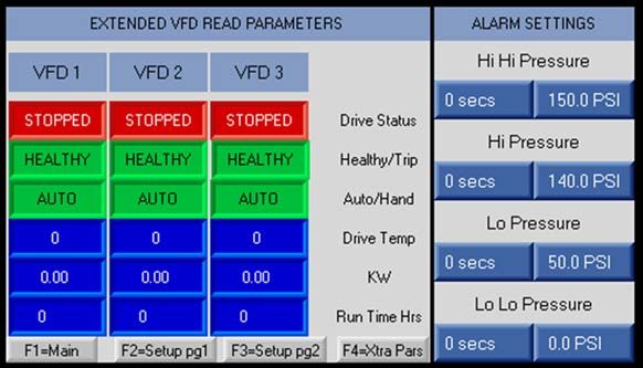
INSTALLATION
Physical Installation

INSTALLATION
Physical Installation

                 Risk of severe injury or death.

         •   When lifting or moving heavy components, use suitable lifting equipment, in good condition, rated
             for at least 5 times the weight of the materials being moved.

         Risk of bodily injury or property damage.
         • Pumps can develop very high pressure in some situations. Always install a pressure relief valve able
            to pass the full pump flow.
         • Install the pressure relief valve near the pressure tank and route to a drain capable of full system
            flow.
         • Ensure that the foundation is rated to accommodate the operating weight of the package and that it
            is sized sufficiently for the weight and loads the package will experience.
         • Do not over tighten piping connections on the fittings used to connect the site plumbing to each
            header as this could damage the equipment and/or headers.
    1. Mount the package to a level foundation of suitable mass and rigidity using 0.50” bolts.
       • Consult a building professional.
    2. Attach the discharge end cap to the opposite side of the discharge header from
       the incoming site water connection using one of the provided couplings.
    3. Attach the suction end cap to the opposite side of the suction header using the
       other coupling.
    4. Make piping connections for the site water.
       • The suction and discharge can be connected to either end of the manifolds.
    5. Install isolation valves near both the inlet and outlet of the packaged assembly.
       • These valves aid with startup loads and prevent full discharge draining during
            maintenance.
    6. Install an appropriately sized pressure relief valve on the discharge side of the
       pump.
    7. Refer to the VFD Owner’s Manual for setup instructions.

4
INSTALLATION
                                                                                                                 Electrical Connections

Electrical Connections

               Risk of severe injury or death by electrical shock.

       •    To minimize risk of electrical shock, disconnect power before working on or around the system.
       •    Capacitors inside the drive can still hold lethal voltage even after power has been disconnected—
            ALLOW 5 MINUTES FOR DANGEROUS INTERNAL VOLTAGE TO DISCHARGE BEFORE REMOVING
            COVER OR WORKING WITH INTERNAL COMPONENTS.
       •    Once site power has been provided to the control panel and those feeds are live, there will be ener-
            gized electrical lines in the control panel up to the remote disconnect terminals even when the
            panel's remote disconnect switch is off. Always de-energize the site power feeding the control panel
            when opening the panel; otherwise, an electrical shock hazard will still exist which can cause serious
            injury, death and major property damage.
   •       Refer to the VFD Owner’s Manual and the VR Pump Owner’s Manual for proper wiring, installation and
           electrical instructions, and hazards.
   •       The base booster pump package comes with pre-wired VFDs and an
           electrical control panel.
   •       Provide power and ground wiring sized for the voltage, phase and
           fuse size listed on the UL 508A labeled panel. Terminate the power
           wiring on the panel's fused disconnect and land the ground wire on
           the sub panels electrical stud.

HMI Digital Outputs Wiring
           NOTE: Some packages come without an HMI and, therefore, do not need wiring to the VFD.

              HMI Relay Output                     HMI Terminals                     VFD #
                     O1                                1&2                             1
                    O2                                 3&4                             2
                    O3                                 5&6                             3
                    O4                                 7&8                             4

                                                                                                                                     5
DRIVE CONFIGURATION
Multi-Drive Configuration

DRIVE CONFIGURATION
Multi-Drive Configuration
    •   Refer to the VFD Owner’s Manual for additional details as setup instructions will vary.
    •   The VFDs are configured to act as the central command structure for the package. One VFD is desig-
        nated as the Master to provide cascade and speed control for all other VFD units.
    •   Master status can be switched between the VFDs by setting the correct parameter when the drive is in
        Hand Mode and turned off.
    •   The package is configured to operate the pumps in a Lead/Lag fashion. Lead and lag roles are set by
        the Master VFD.
    •   The lead pump designation will rotate so all VFDs will run about the same amount of time and not
        exceed the hours set in the Pump Duty Switch Over Time parameter. Refer to “VFD Parameter Screens 1
        & 2” on page 9 to modify this parameter with the Master VFD Control HMI Menu.

Pump Discharge Pressure Sensing
    The pump discharge pressure is measured using one of the pressure transducers installed (per pump) and
    wired into one of the analog inputs (AI). Refer to the VFD manual provided for the specific input terminal
    number.
        • For VFD discharge pressure sensing during operation, refer to “VFD Discharge Pressure Sensing”
             on page 14.
        • Refer to the VFD Owner’s Manual for additional details as setup instructions will vary.

Pump Suction Pressure Sensing
    To prevent pump damage during periods of abnormally low suction pressure, each pump circuit is equipped
    with a Low Pressure Switch (LPS) on the inlet side to the pump(s). The LPS is normally open and closes
    above 5 PSI.
         • The switch is wired into the enable circuit on each VFD control terminal connection block (digital
             input) to keep the string powered and the VFD enabled as long as the switch reads pressures
             above 5 PSI.
         • Refer to the VFD Owner’s Manual for additional details as setup instructions will vary.

6
DRIVE CONFIGURATION
                                                                                        Master VFD Control HMI Menu Settings

Master VFD Control HMI Menu Settings

    Risk of damage to equipment.
    • Only use fingers or proper pointing devices, which have rubber tips, for pressing against the Master
       VFD Control HMI touchscreen. Using pencils, pens, and screwdrivers could result in damaging the
       screen.
   Some units are equipped with a color touchscreen mounted to the
   Master VFD Control HMI face.
   • The touchscreen acts as an operating interface to control all VFD
       programming and displays system conditions, trending informa-
       tion, and alarm information.
   • The Master VFD Control HMI communicates with the Master VFD
       via Modbus and can read/write information to all VFDs.
   • While PID control of the VFDs is still provided by the Master VFD,
       PID control constants can be set in the Master VFD Control HMI
       and written to the VFDs.

Master VFD Control HMI Function Keys
   The function keys along the bottom will display the following screens:

                            1            2             3             4          5

   1.   Main Screen
   2.   VFD Parameter Screen 1
   3.   VFD Parameter Screen 2
   4.   Pump Status and Alarm Point Setting
   5.   Main Screen
   NOTE: With the exception of the Main Screen, all screens require entry of the system passcode before view-
   ing. Refer to “System Passcode” on page 12 for more details.

                                                                                                                          7
DRIVE CONFIGURATION
Master VFD Control HMI Menu Settings

Master VFD Control HMI Main Screen
    The main screen is displayed on power up or by pressing the F1 button.

                                                                                10
                        5                                          7

                                                                                             1

                        6                                               2
                                                               8
                                                                                             3
                    8
                                                                            9               4

    1.   System Status: shows whether the overall package is on or off.
         • Pressing the red “OFF” button sends a disable command to the VFDs.
         • Pressing the green “ON” button sends an enable command to the pump VFDs.
         • A text field is shown above the button to indicate the overall state the On/Off button.
         NOTE: Enabling the pump does not make it run, but allows the pump to run when the system pressure
         is below the setpoint if the VFD is not in a fault condition.
    2. Alarm System Information: displays an alarm or warning with errors.
       • For alarms, an “Active Shutdown Alarms” icon displays along with a text icon describing the fault.
            For example, “Lo Lo Pressure” is displayed in the figure above.
       • Refer to “Alarm Settings” on page 10.
    3. Alarm Log Button: refer to “Alarm Log Screen” on page 13.
    4. Alarm Acknowledge Button: stops the alarm buzzer when pressed.
    5. Individual Pump Enable Buttons: enables or disables the specified pump when pressed.
         IMPORTANT: The enable buttons follow the order of the pumps on the physical rack. If the left pump is
         changed from master status, the enable buttons will not move on the screen. The leftmost enable but-
         ton will always control the leftmost pump.
    6. Current Running State: shows the specific VFD field address and status.
        • When the pump is running, the icon will turn green and the text “ON” appears.
        • When the pump is off, the icon will be red and the text “OFF” will appear.
        • The VFD address number is displayed in the upper right corner on the VFD display screen.
    7. Boost Button: when enabled (“BOOST ON”), the lead pump will run at a frequency 3 Hz higher than
        the Standby Activation Speed for 2 seconds. Then it will go into standby mode.
    8. Live Operating Information: displays the system’s pressure setpoint (PSI), output frequency (HZ), out-
        put current (A), and discharge pressure (PSI).
    9. Trend Screen Button: refer to “Trend Screen” on page 11.
    10. System/Project Info Button: refer to “System/Project Info Screen” on page 12.

8
DRIVE CONFIGURATION
                                                                                        Master VFD Control HMI Menu Settings

VFD Parameter Screens 1 & 2
   •    VFD Parameter Screen 1 and 2 are viewed by pressing F2 or F3 respectively.
   •    Access to either screen requires entering the system passcode. Refer to “System Passcode” on page 12.
   •    The current settings dictating VFD performance are shown in the Column marked CURRENT.
   To update system operating values for either screen:

                                                                    3           1

   1.   Press the applicable button under the NEW column.
   2.   Enter the new value in the input screen. Press the return button.
        • If the input is beyond the allowable range, the return button will not operate.
   3.   Verify the updated value is shown in the NEW column.
        • The value will be written into each of the VFDs.
        • Once the value has been read back by the Master VFD Control HMI, the CURRENT column will
             update.
VFD Parameter Locations:
                 Screen                                            Parameter
                                       Acceleration Ramp Speed
                                       Deceleration Ramp Speed
                                       PID Proportional Gain
                                       PID Integral Time
         VFD Parameter Screen 1
                                       PID Differential Time
                                       Minimum VFD Speed
                                       Maximum VFD Speed
                                       *Pressure Setpoint (in PSI)
                                       Pressure Transducer Range
                                       *Pump Duty Switch Over Time
                                       Standby Activation Speed
                                       Standby Mode Timer
        VFD Parameter Screen 2
                                       *Assist Pump Start Speed
                                       *Assist Pump Stop Speed
                                       *Assist Pump Settling Time
                                       **Wake Up Differential
   *NOTE: These parameters are preset in the factory.
   **NOTE: Wake Up Differential represents the percentage of pressure transducer range to be used to trigger
   the wake-up call.

                                                                                                                          9
DRIVE CONFIGURATION
Master VFD Control HMI Menu Settings

Extended VFD Parameters and Alarm Settings Screen
     Viewed by pressing the F4 button, this screen shows additional information about VFD read parameters and
     system alarm settings.
     Access the screen requires entering the system passcode. Refer to “System Passcode” on page 12.

Extended VFD Read Parameters
     This section of the screen shows current details of the VFD read parameters, including:
          • Drive status: STOPPED (red) or RUNNING (green)
          • Healthy/Trip
          • Auto/Hand: current mode
          • Drive Temp: internal drive temperature in Celsius
          • kW: instantaneous power draw by drive in KW
          • Run Time Hrs: actual VFD operating run time in hours
Alarm Settings
     When a fault occurs, the Master VFD Control HMI Main screen will display the fault type and the alarm
     buzzer will sound.
         • Warnings do not stop pump operation.
         • Alarm trips disable pump operation. The system will not enable the pumps again until the condi-
             tion is corrected.
         • To silence the alarm buzzer, press the “Alarm Acknowledge” button on the Main Screen. Refer to
             “Master VFD Control HMI Main Screen” on page 8.
     The current alarm timers and levels are displayed and can be updated by pressing the corresponding button
     of the desired setting.
          • Time settings are the amount of seconds that the pressure settings (PSI) needs to be exceeded
              before the fault condition is triggered.

        Fault          Fault Type                                   Description
                                       The discharge pressure reading is above the set level. The program regis-
  Hi Hi Pressure           Trip
                                       ters a HIGH PRESSURE ALARM and disables the pump.
                                       The discharge pressure reading is above the set level. The program regis-
     Hi Pressure         Warning
                                       ters a HIGH PRESSURE WARNING. Pump operation is not stopped.
                                       The discharge pressure reading is below the set level. The program regis-
     Lo Pressure        Warning
                                       ters a LOW PRESSURE WARNING. Pump operation is not stopped.
                                       The discharge pressure reading is below the set level. The program regis-
  Lo Lo Pressure           Trip
                                       ters a LOW PRESSURE ALARM and disables the pump.

10
DRIVE CONFIGURATION
Master VFD Control HMI Menu Settings
Trend Screen
• This screen provides a graph of the setpoint pressure value and the measured discharged pressure cur-
rently and historically.
• The setpoint values are plotted in green, while the measured pressure values are in red.
• To navigate to the screen, refer to “Master VFD Control HMI Main Screen” on page 8.
To customize the screen:
2 1
5
4
1. Press the “Hide Press SP Trend” button to hide or display the pressure setpoint.
2. Press the “Hide Press PV Trend” to hide or display the discharge pressure reading.
3. Change the min and max scale values along the vertical axis by selecting the desired graph line and
then pressing on the respective upper and lower numbers.
• A prompt to enter a new value will display.
• The new value will update after pressing the return key.
4. Show or hide the horizontal grid lines by pressing the “G” button.
5. View historic graph views by pressing the “M” button.
• Arrow toggle buttons will appear for navigation to the desired time period.
11DRIVE CONFIGURATION
Master VFD Control HMI Menu Settings
System/Project Info Screen
To navigate to this screen, refer to “Master VFD Control HMI Main Screen” on page 8.
1
2
3
1. Change Password button: validates and alters the new passcode entered. Refer to “System Passcode”
on page 12 to change the system passcode.
2. Project Info button: displays a screen with customizable information provided at the time of purchase.
• Screen headings include “Project Information” and “Spare Parts”.
3. “Press until Calibrate Screen appears” button: refer to “Calibrate Screen” on page 13.
System Passcode
• When accessing any of the setup screens, a passcode screen will appear.
• The factory preset passcode is “0” (zero).
• For security purposes, the value shown in the “Passcode” field always displays as “0” and does not rep-
resent the actual value.
To update the system passcode:
1
1. Press the display field to the right of the “Current Pass-
code” text label to bring up the “Passcode Change”
input screen. 6
2. Enter the current passcode on the input screen that 4
appears.
3. Hit the return key.
4. Press the display field to the right of the “New Pass-
code” text lable to bring up the “New Passcode” screen.
5. Enter the new passcode on the input screen.
Hit the return key.
• Refer to step 3 and the graphic.
6. Press the Change Password button on the System/
Project Info screen. 3
NOTE: The new passcode is accepted if the values in
both fields return to “0” on the screen.
12DRIVE CONFIGURATION
Master VFD Control HMI Menu Settings
Calibrate Screen
3
1
2
1. Enter Info Mode button: secured access to Info Mode where advanced system settings such as memory
bits, system integers, and time zones are set. For entry, adjustments and more details, consult the fac-
tory or Technical Support.
2. Calibrate Touchscreen button: brings up a screen to coordinate the screen buttons with the user’s
physical touch. Small buttons will appear one at a time on the screen for the user to press so the touch-
screen accurately represents the system information and responds to input. To exit before fully cali-
brated, press the ESC button.
3. ESC button: exits the screen.
Alarm Log Screen
• This screen provides an overview of present and historical faults registered by the system.
• The alarms are listed by group.
• To navigate to the screen, refer to “Master VFD Control HMI Main Screen” on page 8.
4
2 1
3
1. Search button: displays detailed fault information, including a list of specific alarms registered and
whether it was acknowledged.
• Further information can be viewed by pressing the button again.
2. Reset button: clears the alarm count.
3. Refresh button: alarm log page is refreshed.
4. ESC button: exits the screen.
• The screen can also be exited using any of the function keys.
13OPERATION
VFD Discharge Pressure Sensing
OPERATION
VFD Discharge Pressure Sensing
Refer to the VFD Owner’s Manual for additional details as setup instructions will vary.
• The pump system maintains a set discharge pressure by comparing it to a user defined setpoint. Then
the system adjusts the speed of the pump motor VFDs to achieve that setpoint.
• During no flow periods, the VFDs will stop the pump motors and enter standby mode. The system will
stay in the ready state until the discharge pressure drops and water demand resumes. Refer to
“Standby Activation Speed” on page 15.
• The lead pump will be the first pump dispatched to meet the pressure setpoint established in the VFD.
• The pump motor speed will be bounded by the minimum and maximum speed settings established in
VFD parameters the speed driven by the PID control algorithm in the VFD.
Assist Pump Speed Parameters
Three factory preset VFD parameters control the speed at which additional assist pumps are activated or
deactivated to aid the lead pump. Refer to the VFD Owner’s Manual for additional details as setup instruc-
tions will vary. Within the Master VFD Control HMI they are:
1. Assist Pump Settling Time: the wait period, in seconds, before assist pumps are activated or deacti-
vated.
2. Assist Pump Start Speed: the maximum speed the lead pump will run without more assistance before
the Assist Pump Settling Time is reached.
• If the lead pump is operated above the Assist Pump Start Speed for a period of time exceeding the
Pump Settling Time, the Master VFD will start a lag pump and drive both at the same speed.
• In Triplex and Quad packages, additional pumps will be activated to assist if needed.
3. Assist Stop Speed: the minimum speed at which the assist pumps will run before the Assist Pump Set-
tling Time is reached.
• Once the pumps operate at a speed lower than the Assist Pump Stop Speed for a period of time
exceeding the Pump Settling Time, assist pumps are deactivated one at a time.
• This parameter may be adjusted to have the assist pumps stay on longer or shut down sooner.
NOTE: Assist Stop Speed should be higher than the Standby Activation Speed setting. Refer to
“Standby Activation Speed” on page 15.
All three parameters can be viewed or modified in the VFD Parameter Screen 2 of the Master VFD Control
HMI. When setting the parameters, be sure to consider pump efficiency curves, pump operating ranges, and
any constraints to minimize pump run times. Refer to “VFD Parameter Screens 1 & 2” on page 9.
Refer to the VFD Owner’s Manual for setting the speed parameters individually.
14OPERATION
Standby Activation Speed
Standby Activation Speed
The Standby Activation Speed is the speed representing a no flow condition of the pump preset at the fac-
tory. It can be determined by dead heading the lead pump and recording the pump speed. Refer to the VFD
Owner’s Manual for additional details as setup instructions will vary. The parameter can be updated in the
VFD Parameter Screen 2 of the Master VFD Control HMI. Refer to “VFD Parameter Screens 1 & 2” on page 9.
NOTE: Programming a Standby Activation Speed of 1-3 HZ above the value has the VFD go into
standby mode during no flow periods.
When the lead pump motor is operated at a speed lower than the Standby Activation Speed for a period of
time exceeding the Standby Mode Timer, the lead pump is taken off-line and placed in a standby status. The
lead pump will remain in standby until the Master VFD measures a pressure less setpoint minus the PID
Restart Error Level.
• Refer to the VFD Owner’s Manual for additional details as setup instructions will vary.
• To set the Standby Mode Timer or the PID Restart Error Level via the Master VFD Control HMI, refer
to “VFD Parameter Screens 1 & 2” on page 9.
Boost Function
A boost function can be enabled so that the lead pump will run at a higher speed for a period of time before
going into standby mode. This can be set up by programming a boost Speed Time for a value greater than 0
(this value is the seconds the boost will operate at) and setting the boost speed in the Preset Speed.
• Refer to the VFD Owner’s Manual for additional details as setup instructions will vary.
• To activate the boost feature via the Master VFD Control HMI Menu, refer to “Master VFD Control
HMI Main Screen” on page 8.
VFD PID Setpoint Pressure
• The VFD PID reference parameter represents the pressure transducer range.
• The setpoint pressure is calculated internally by the VFD by dividing Pressure Setpoint by Pressure
Transducer Range. Refer to “VFD Parameter Screens 1 & 2” on page 9 to change these parameters via
the Master VFD Control HMI Menu.
• Refer to the VFD Owner’s Manual for additional details as setup instructions will vary for individual
drives.
• If a replacement drive is installed without this function block programming, the discharge pressure set-
point will need to be manually entered in the VFD. Refer to the owner’s manual for instructions.
Pre-Start Verifications
1. Check electrical incoming voltage meets requirements and an adequate ground connection exists.
2. Inspect the overall system for damage during installation.
3. Pressurize the system with the site water to remove any trapped air.
4. If there are any water leaks in the piping, isolate the location and tighten the connections.
• If the leaks are at the threaded connections in the piping circuits, tighten each fitting so the suction
and discharge manifolds equally distanced.
15OPERATION
Starting the Package
Starting the Package
1. Power on the VFDs, switching their disconnect switches to the ON position.
• Refer to the VFD Owner’s Manual.
• Each VFD should be in Hand Mode and turned off. Refer to the VFD Owner’s Manual for details on
Hand and Auto Mode.
2. Make sure the VFD Setpoint Pressure for the unit is correct. Refer to “VFD PID Setpoint Pressure” on
page 15.
3. Verify the Standby Activation Speed is correct.
• Refer to “Standby Activation Speed” on page 15.
• Isolate out the pumps to find the dead head speed corresponding to the site pressure setpoint.
• Add 1-3 HZ to that number to find the speed at which the pumps go into standby mode if they
operate at this frequency for the time period set in the Standby Mode Timer.
• If the number calculated is different, update the Standby Activation Speed to the new value. Refer
to “VFD Parameter Screens 1 & 2” on page 9 for entry via the Master VFD Control HMI Menu.
4. Verify Assist Pump Start and Stop speeds are correct. Refer to “Assist Pump Speed Parameters” on
page 14.
5. Place each VFD in Auto Mode and turn on. Refer to the VFD Owner’s Manual.
6. Verify that the pump rotates clockwise when looking down at the motor.
• If rotation is incorrect, change the phasing in the parameter setting at the VFD.
• Refer to the VFD Owner’s Manual.
7. If needed, place each VFD in Hand mode and turn off to adjust the PID Proportional Gain, PID Integral
Time, and PID Differential Time parameters to optimize pump performance for system demand
changes.
• Refer to “VFD Parameter Screens 1 & 2” on page 9 for entry via the Master VFD Control HMI Menu.
NOTE: For maintenance and troubleshooting of the VFDs and pumps, refer to their owner’s manuals.
For technical assistance, parts, or repair, please contact:
800.348.2420 | franklinwater.com
Form 10000007073 Rev. 001 04/21 Copyright © 2021, Franklin Electric, Co., Inc. All rights reserved.ES ESPAÑOL
VR Spec PAK
Manual del propietario
Indice
DESCRIPCIÓN DEL PRODUCTO - - - - - - - 19
Descripción - - - - - - - - - - - - - - 19
INSTALACIÓN - - - - - - - - - - - - - - 20
Instalación física - - - - - - - - - - 20
Conexiones eléctricas - - - - - - - - - 21
CONFIGURACIÓN DEL VARIADOR - - - - -22
Configuración del variador múltiples- -22
Detección de la presión de descarga
de la bomba - - - - - - - - - - - - -22
Detección de presión de succión de la
bomba- - - - - - - - - - - - - - - -22
Ajuste del menú de la HMI de control
del VFD principal - - - - - - - - - - -23
FUNCIONAMIENTO - - - - - - - - - - - -30
Detección de la presión de descarga
del VFD- - - - - - - - - - - - - - - -30
Parámetros de velocidad de la bomba
de asistencia - - - - - - - - - - - - -30
Velocidad de activación en espera - - - 31
Presión del punto de referencia del PID
del VFD- - - - - - - - - - - - - - - - 31
Verificaciones previas al arranque - - - 31
Arranque del paquete - - - - - - - - -32
franklinagua.comINSTRUCCIONES SOBRE SEGURIDAD
INSTRUCCIONES SOBRE SEGURIDAD
La instalación y el mantenimiento de este equipo deben estar a
cargo de personal con capacitación técnica que esté familiarizado
con la correcta elección y uso de las herramientas, equipos y pro- Riesgo de lesiones corporales,
cedimientos adecuados. El hecho de no cumplir con los códigos descargas eléctricas o daños materiales.
eléctricos nacionales y locales y con las recomendaciones de • Este equipo no deben usarlo niños ni personas con capacidades
Franklin Electric puede provocar peligros de descarga eléctrica o físicas, sensoriales o mentales reducidas, ni aquellos que carez-
incendio, desempeños insatisfactorios o fallas del equipo. can de experiencia y capacitación, salvo que estén bajo supervi-
Lea y siga las instrucciones cuidadosamente para evitar lesiones y sión o instrucción. Los niños no podrán usar el equipo ni jugar
daños a los bienes. No desarme ni repare la unidad salvo que esté con la unidad o en las cercanías inmediatas.
descrito en este manual. • El equipo puede encenderse en forma automática. Realice los
procedimientos de bloqueo/etiquetado antes de efectuar el
El hecho de no seguir los procedimientos de instalación o funcio- mantenimiento del equipo.
namiento y todos los códigos aplicables puede ocasionar los • Posibles superficies calientes. No toque las bombas durante el
siguientes peligros: funcionamiento. Deje que todos los componentes del paquete se
enfríen durante 30 minutos antes de manipularlos.
• El funcionamiento de este equipo exige instrucciones detalladas
Riesgo de muerte, lesiones graves o para su instalación y funcionamiento que se encuentran en este
daños materiales por explosión, manual para su uso con este producto. Lea la totalidad del manual
antes de comenzar la instalación y la operación. El usuario final
incendio o descarga eléctrica.
debe recibir y conservar el manual para usos futuros.
• No usar para bombear líquidos inflamables, combustibles o
explosivos como gasolina, combustóleo, queroseno, etc.
• No usar en atmósferas explosivas ni lugares peligrosos según la
clasificación de la NEC, ANSI/NFPA70. Riesgo de daños a bomba u otros equipos.
• No manipule la bomba ni el motor de la bomba con las manos • Inspeccione periódicamente los componentes del sistema y la
mojadas o parado sobre una superficie mojada o húmeda o en bomba. Revise regularmente las mangueras para controlar si
agua. están débiles o gastadas y asegúrese de que todas las conexio-
nes sean seguras.
Riesgo de muerte o lesiones graves.
• Para reducir el riesgo de descarga eléctrica, desconecte la ener-
gía antes de trabajar en el sistema o cerca de él. Es posible que
sea necesario más de un interruptor de desconexión para cortar
la energía del equipo antes de realizarle un mantenimiento.
• Compruebe los códigos eléctricos y de construcción locales antes
de la instalación. La instalación debe estar de acuerdo con sus
regulaciones, así como el National Electrical Code (NEC) más
reciente y la ley de Seguridad y Salud Ocupacionales (OSHA).
• Cablee el sistema de bombeo para los voltajes correctos.
• Asegúrese de que el sistema esté correctamente conectado a
tierra en todo su tramo hasta el panel de acometida.
• Cuando levante o mueva componentes pesados, use equipo de
elevación adecuado, en buenas condiciones, clasificado para un
mínimo de cinco veces el peso de los materiales a mover.
• Los capacitores dentro el variador pueden seguir conservando
un voltaje letal incluso después de haber desconectado la ener-
gía. ESPERE 5 MINUTOS PARA QUE EL VOLTAJE INTERNO PELI-
GROSO SE DISIPE ANTES DE QUITAR LA CUBIERTA O TRABAJAR
CON COMPONENTES INTERNOS.
18DESCRIPCIÓN DEL PRODUCTO
Descripción
DESCRIPCIÓN DEL PRODUCTO
Descripción
VR SpecPAK incluye dos, tres o cuatro bombas VR controladas por variadores de fre-
cuencia independientes, como los variadores de frecuencia Q-Link, el variador Inver-
tek o el Cerus X-Drive.
Las bombas verticales de etapas múltiples serie VR se encuentran disponibles en
opciones de 3 a 30 m3/h (16 a 160 GPM) en el punto de máxima eficiencia con todas
las piezas hidráulicas internas de acero inoxidable 316 para brindar una durabilidad,
eficiencia y rendimiento superiores. Su tamaño pequeño, motor de primera calidad y
componentes resistentes garantizan una larga vida útil que ofrece una solución de
bombeo de agua en casi cualquier aplicación complicada. Las bombas son aptas
para el suministro de agua y los sistemas de elevación de presión, riego y agricul-
tura, el tratamiento de agua y las aplicaciones de climatización. Para obtener más
información y ayuda durante la instalación o el mantenimiento, consulte el manual
del propietario de la bomba VR que se incluye.
Los variadores de frecuencia (VFD, por sus siglas en inglés) dentro del paquete están
diseñados para controlar y proteger los motores de la bomba. Para obtener más
información y ayuda durante la instalación o el mantenimiento, consulte el manual
del propietario del VFD que se incluye.
Es posible que el paquete venga con una pantalla HMI (interacción persona/
máquina) opcional de control del VFD principal. Con esta pantalla de control, el
usuario puede actualizar los parámetros de cada VFD individual, lo que facilita el
control de las bombas en paquete en vez individualmente. Los parámetros incluyen velocidad de rampa de aceleración y desacele-
ración; información del PID; velocidad del VFD; valor de presión establecido; rango del transductor de presión; cambio de servicio
de la bomba con el tiempo; velocidad de activación en espera y temporizador de modo; velocidad de arranque, parada y estabiliza-
ción de la bomba de asistencia; y diferencial de reactivación.
Los componentes del paquete en conjunto no tienen la misma garantía. Para obtener información sobre la garantía, consulte el
manual del propietario de cada componente.
¿Qué se incluye?
1. Listado de parámetros del VFD para bombas
2. Acoples (2)
3. Tapones ranurados 304SS (2)
4. Manual del propietario del variador de frecuencia (VFD)
5. Manual del propietario de la bomba VR
6. Manual del propietario de VR SpecPAK
19INSTALACIÓN
Instalación física
INSTALACIÓN
Instalación física
Riesgo de muerte o lesiones graves.
• Cuando levante o mueva componentes pesados, use equipo de elevación adecuado, en buenas con-
diciones, clasificado para un mínimo de cinco veces el peso de los materiales a mover.
Riesgo de lesiones corporales o daños materiales.
• En algunas situaciones, las bombas pueden generar una presión muy alta. Siempre instale una vál-
vula de alivio de presión que pueda permitir el paso del flujo total de la bomba.
• Instale la válvula de alivio de presión cerca del tanque de presión y dirijala a un desagüe capaz de
flujo completo del sistema.
• Asegúrese de que la base esté clasificada para acomodar el peso de funcionamiento del paquete y
que tenga el tamaño suficiente para el peso y las cargas a las que será sometido el paquete.
• No ajuste excesivamente las conexiones de tuberías en los accesorios utilizados para conectar la plo-
mería del sitio a cada cabezal, ya que esto podría dañar el equipo o los cabezales.
1. Monte el paquete en una base nivelada de masa y rigidez adecuadas usando pernos de 12.7 mm (0.50 pulg.)
• Consulte a un profesional de la construcción.
2. Coloque el tapón del extremo de descarga en el lado opuesto del cabezal de
descarga de la conexión de agua entrante del sitio utilizando uno de los acoples
provistos.
3. Coloque el tapón del extremo de succión en el lado opuesto del cabezal de suc-
ción utilizando el otro acople.
4. Realice las conexiones de las tuberías para el agua del sitio.
• La succión y la descarga se pueden conectar a cualquier extremo de los
múltiples.
5. Instale válvulas de aislamiento cerca de la entrada y la salida del conjunto
empaquetado.
• Estas válvulas ayudan con las cargas de arranque y evitan el drenaje com-
pleto de la descarga durante el mantenimiento.
6. Instale una válvula de alivio de presión de tamaño adecuado en el lado de des-
carga de la bomba.
7. Consulte el manual del propietario del VFD para obtener instrucciones sobre
ajustes.
20INSTALACIÓN
Conexiones eléctricas
Conexiones eléctricas
Riesgo de lesiones graves o muerte por descarga eléctrica.
• Para minimizar el riesgo de descarga eléctrica, desconecte la energía antes de trabajar en o alrede-
dor del sistema.
• Los capacitores dentro el variador pueden seguir conservando un voltaje letal incluso después de haber desco-
nectado la energía. ESPERE 5 MINUTOS PARA QUE EL VOLTAJE INTERNO PELIGROSO SE DISIPE ANTES DE
QUITAR LA CUBIERTA O TRABAJAR CON COMPONENTES INTERNOS.
• Una vez que se haya suministrado la alimentación del sitio al panel de control y que la alimentación
esté activa, habrá líneas eléctricas energizadas en el panel de control que lleguen a los terminales de
desconexión remota incluso cuando el interruptor de desconexión remota del panel esté apagado.
Siempre desenergice la alimentación del sitio del panel de control cuando abra el panel; de lo con-
trario, seguirá habiendo un riesgo de descarga eléctrica que puede provocar lesiones graves, la
muerte y daños materiales importantes.
• Consulte el Manual del propietario del VFD y el Manual del propietario de la bomba VR para conocer el cableado adecuado, las
instrucciones eléctricas y de instalación y los peligros.
• El paquete base de la bomba elevadora de presión viene con los
VFD ya cableados y con un panel de control eléctrico.
• Proporcione cableado de alimentación y conexión a tierra del
tamaño adecuado para el voltaje, la fase y el fusible que figuran en
el panel etiquetado UL 508A. Termine el cableado de alimentación
en la desconexión con fusible del panel y conecte el cable de tierra
al perno eléctrico de los subpaneles.
Cableado de las salidas digitales de la HMI
NOTA: Algunos paquetes vienen sin HMI (interacción hombre/máquina) y, por lo tanto, no requieren cableado al VFD.
Salida de relé de la HMI Terminales de la HMI N.º de VFD
O1 1&2 1
O2 3&4 2
O3 5&6 3
O4 7&8 4
21CONFIGURACIÓN DEL VARIADOR
Configuración del variador múltiples
CONFIGURACIÓN DEL VARIADOR
Configuración del variador múltiples
• Consulte el Manual del propietario del VFD para obtener información detallada adicional, ya que las instrucciones sobre ajustes
pueden variar.
• Los VFD (variadores de frecuencia) están configurados para actuar como la estructura de comando central del paquete. Uno de
los VFD está designado como principal para proporcionar el control de velocidad y cascada de todos los demás VFD.
• El estado de principal se puede intercambiar entre los VFD ajustando el parámetro correcto cuando el variador está en modo
manual y apagado.
• El paquete está configurado para hacer funcionar las bombas en forma de principal/secundaria. Los roles de principal y secun-
daria los establece el VFD principal.
• La designación de la bomba principal irá rotando para que todos los VFD funcionen aproximadamente la misma cantidad de
tiempo y no excedan las horas establecidas en el parámetro “Cambio de servicio de la bomba con el tiempo”. Consulte “Pan-
tallas 1 y 2 de parámetros del VFD” en la página 25 para modificar este parámetro con el menú de la HMI de control del VFD
principal.
Detección de la presión de descarga de la bomba
La presión de descarga de la bomba se mide utilizando uno de los transductores de presión instalados (en cada bomba) y conecta-
dos a una de las entradas analógicas (AI). Consulte el manual del VFD provisto para conocer el número específico del terminal de
entrada.
• Para detectar la presión de descarga del VFD durante el funcionamiento, consulte “Detección de la presión de descarga
del VFD” en la página 30.
• Consulte el Manual del propietario del VFD para obtener información detallada adicional, ya que las instrucciones sobre
ajustes pueden variar.
Detección de presión de succión de la bomba
Para no dañar la bomba durante períodos de presión de succión anormalmente baja, cada circuito de la bomba está equipado con
un interruptor de baja presión (LPS, por sus siglas en inglés) en el lado de entrada a las bombas. El LPS normalmente está abierto y
se cierra cuando se superan los 5 PSI.
• El interruptor está conectado al circuito de activación en cada bloque de conexión del terminal de control del VFD
(entrada digital) para mantener la cadena alimentada y el VFD activado siempre y cuando el interruptor detecte presiones
superiores a 5 PSI.
• Consulte el Manual del propietario del VFD para obtener información detallada adicional, ya que las instrucciones sobre
ajustes pueden variar.
22CONFIGURACIÓN DEL VARIADOR
Ajuste del menú de la HMI de control del VFD principal
Ajuste del menú de la HMI de control del VFD principal
Riesgo de daños al equipo.
• Utilice únicamente los dedos o dispositivos de señalización adecuados, que tengan puntas de goma,
para presionar contra la pantalla táctil de la HMI de control del VFD principal. El uso de lápices, bolí-
grafos y destornilladores podría dañar la pantalla.
Algunas unidades están equipadas con una pantalla táctil a color mon-
tada en el frente de la HMI de control del VFD principal.
• La pantalla táctil actúa como interfaz operativa para controlar toda
la programación del VFD y muestra estados del sistema, informa-
ción de tendencias e información de alarmas.
• La HMI de control del VFD principal se comunica con el VFD princi-
pal a través de Modbus y puede leer/escribir información en todos
los VFD.
• Si bien el control del PID de los VFD todavía lo proporciona el VFD
principal, las constantes de control del PID se pueden configurar
en la HMI de control del VFD principal y escribir en los VFD.
Teclas de función de la HMI de control del VFD principal
Las teclas de función en la parte inferior sirven para mostrar las siguientes pantallas:
1 2 3 4 5
1. Pantalla principal (Main Screen)
2. Pantalla 1 de parámetros del VFD (VFD Parameter Screen 1)
3. Pantalla 2 de parámetros del VFD (VFD Parameter Screen 2)
4. Estado de la bomba y ajustes del valor de alarma (Pump Status and Alarm Point Setting)
5. Pantalla principal (Main Screen)
NOTA: Con excepción de la pantalla principal, todas las pantallas requieren que ingrese la contraseña del sistema antes de poder
verlas. Consulte “Contraseña del sistema” en la página 28.
23CONFIGURACIÓN DEL VARIADOR
Ajuste del menú de la HMI de control del VFD principal
Pantalla principal de la HMI de control del VFD principal
La pantalla principal aparece cuando se enciende el dispositivo o cuando se presiona el botón F1.
10
5 7
1
6 2
8
3
8
9 4
1. Estado del sistema: muestra si el paquete general está encendido o apagado.
• Al presionar el botón rojo “OFF” (APAGADO) se envía un comando de desactivación a los VFD.
• Al presionar el botón verde “ON” (ENCENDIDO) se envía un comando de activación a los VFD de la bomba.
• Arriba del botón se muestra un campo de texto que indica el estado general del botón de encendido/apagado.
NOTA: El hecho de activar la bomba no la hace funcionar, pero permite que la bomba funcione cuando la presión del sistema
esté por debajo del punto de referencia si el VFD no se encuentra en un estado de falla.
2. Información del sistema de alarma: muestra alarmas o advertencias con errores.
• En el caso de las alarmas, aparece un icono de “Active Shutdown Alarms” (alarmas de apagado activas) junto a un texto
que describe la falla. Por ejemplo, en la figura anterior se muestra “Lo Lo Pressure” (presión baja baja).
• Consulte “Ajustes de alarma (ALARM SETTINGS)” en la página 26.
3. Botón Alarm Log (Registro de alarmas): consulte “Pantalla de registro de alarmas” en la página 29.
4. Botón Alarm Acknowledge (Reconocimiento de alarma): detiene el zumbido de alarma cuando se presiona.
5. Botones activación de bombas individuales: activa o desactiva la bomba especificada cuando se presiona.
IMPORTANTE: Los botones de activación siguen el orden de las bombas en el bastidor físico. Si se cambia la bomba izquierda
desde el estado de principal, los botones de activación no se moverán en la pantalla. El botón de activación ubicado en el
extremo izquierdo siempre controlará la bomba del extremo ubicada en el extremo izquierdo.
6. Estado de funcionamiento actual: muestra la dirección de campo y el estado del VFD específico.
• Cuando la bomba está funcionando, el icono se volverá verde y aparecerá el texto “ON” (ENCENDIDO).
• Cuando la bomba está apagada, el icono será rojo y aparecerá el texto “OFF” (APAGADO).
• El número de dirección del VFD se muestra en la esquina superior derecha de la pantalla de visualización del VFD.
7. Botón Boost (Incremento): cuando esté activado (“BOOST ON”), la bomba principal funcionará a una frecuencia 3 Hz más
alta que la Velocidad de activación en espera durante 2 segundos. Luego pasará al modo de espera.
8. Información de funcionamiento en vivo: muestra el punto de referencia de presión del sistema (PSI), la frecuencia de salida
(HZ), la corriente de salida (A) y la presión de descarga (PSI).
9. Botón Trend Screen (Pantalla de tendencia): consulte “Pantalla de tendencia (Trend)” en la página 27.
10. Botón información del sistema/proyecto: consulte “Pantalla de información del sistema/proyecto” en la página 28.
24CONFIGURACIÓN DEL VARIADOR
Ajuste del menú de la HMI de control del VFD principal
Pantallas 1 y 2 de parámetros del VFD
• Las pantallas 1 y 2 de parámetros del VFD se visualizan presionando F2 o F3, respectivamente.
• El acceso a estas pantallas requiere ingresar la contraseña del sistema. Consulte “Contraseña del sistema” en la página 28.
• Los ajustes actuales que dictan el rendimiento del VFD se muestran en la columna marcada CURRENT (ACTUAL).
Para actualizar los valores operativos del sistema de cualquiera de las pantallas:
3 1
1. Presione el botón que corresponda debajo de la columna NEW (NUEVO).
2. Ingrese el nuevo valor en la pantalla de entrada. Presione el botón de volver.
• Si el valor de entrada excede el rango permitido, el botón de volver no funcionará.
3. Verifique que el valor actualizado aparezca en la columna NEW.
• El valor estará escrito en cada uno de los VFD.
• Una vez que la HMI de control del VFD principal haya leído el valor, la columna CURRENT se actualizará.
Ubicaciones de los parámetros del VFD:
Pantalla Parámetro en pantalla En español
Acceleration Ramp Speed Velocidad de rampa de aceleración
Deceleration Ramp Speed Velocidad de rampa de desaceleración
PID Proportional Gain Ganancia proporcional del PID
Pantalla 1 de paráme- PID Integral Time Tiempo integral del PID
tros del VFD PID Differential Time Tiempo diferencial del PID
Minimum VFD Speed Velocidad mínima del VFD
Maximum VFD Speed Velocidad máxima del VFD
*Pressure Setpoint (in PSI) *Punto de referencia de presión (en PSI)
Pressure Transducer Range Rango del transductor de presión
*Pump Duty Switch Over Time *Cambio de servicio de la bomba con el tiempo
Standby Activation Speed Velocidad de activación en espera
Pantalla 2 de parámetros Standby Mode Timer Temporizador del modo de espera
del VFD *Assist Pump Start Speed *Velocidad de arranque de la bomba de asistencia
*Assist Pump Stop Speed *Velocidad de parada de la bomba de asistencia
*Assist Pump Settling Time *Tiempo de estabilización de la bomba de asistencia
**Wake Up Differential **Diferencial de reactivación
*NOTA: Estos parámetros vienen preestablecidos de fábrica.
**NOTA: Diferencial de reactivación representa el porcentaje del rango del transductor de presión que se utilizará para activar la lla-
mada de reactivación.
25CONFIGURACIÓN DEL VARIADOR
Ajuste del menú de la HMI de control del VFD principal
Pantalla de parámetros extendidos del VFD y ajustes de alarmas
Esta pantalla, que se ve al presionar el botón F4, muestra información adicional sobre los parámetros de lectura del VFD y los ajus-
tes de la alarma del sistema.
El acceso a esta pantalla requiere ingresar la contraseña del sistema. Consulte “Contraseña del sistema” en la página 28.
Parámetros extendidos de lectura del VFD (EXTENDED VFD READ PARAMETERS)
Esta sección de la pantalla muestra los detalles actuales de los parámetros de lectura del VFD, que incluyen:
• Drive status (Estado del variador): STOPPED (DETENIDO, en rojo) o RUNNING (FUNCIONANDO, en verde)
• Healthy/Trip (Saludable/Desconectado)
• Auto/Hand (Automático/Manual): modo actual
• Drive Temp (Temperatura del variador): temperatura interna del variador en grados Celsius
• kW: consumo instantáneo de energía por variador en kW
• Run Time Hrs (Horas de tiempo en ejecución): tiempo de funcionamiento real del VFD en horas
Ajustes de alarma (ALARM SETTINGS)
Cuando ocurre una falla, la pantalla principal de la HMI de control del VFD principal mostrará el tipo de falla y sonará el zumbido de
alarma.
• Las advertencias no detienen el funcionamiento de la bomba.
• Las desconexiones por alarma desactivan el funcionamiento de la bomba. El sistema no volverá a activar las bombas hasta
que se corrija la condición.
• Para silenciar el zumbido de alarma, presione el botón “Alarm Acknowledge” (Reconocimiento de alarma) en la pantalla
principal. Consulte “Pantalla principal de la HMI de control del VFD principal” en la página 24.
Los temporizadores y los niveles de alarma actuales se muestran y se pueden actualizar presionando el botón correspondiente del
ajuste deseado.
• Los ajustes de tiempo corresponden a la cantidad de segundos que deberán excederse los ajustes de presión (PSI) antes
de que se active la condición de falla.
Falla Tipo de falla Descripción
Hi Hi Pressure La lectura de la presión de descarga está por encima del nivel establecido. El pro-grama
Desconexión
(Presión alta alta) registra una ALARMA DE PRESIÓN ALTA y desactiva la bomba.
La lectura de la presión de descarga está por encima del nivel establecido. El pro-grama
Hi Pressure
Advertencia registra una ADVERTENCIA DE PRESIÓN ALTA. El funcionamiento de la bomb-a no se
(Presión alta)
detiene.
La lectura de la presión de descarga está por debajo del nivel establecido. El pro-grama
Lo Pressure
Advertencia registra una ADVERTENCIA DE PRESIÓN BAJA. El funcionamiento de la bomb-a no se
(Presión baja)
detiene.
Lo Lo Pressure La lectura de la presión de descarga está por debajo del nivel establecido. El pro-grama
Desconexión
(Presión baja baja) registra una ALARMA DE PRESIÓN BAJA y desactiva la bomba.
26CONFIGURACIÓN DEL VARIADOR
Ajuste del menú de la HMI de control del VFD principal
Pantalla de tendencia (Trend)
• Esta pantalla proporciona un gráfico del valor de presión del punto de referencia y la presión de descarga medida en forma
actual e histórica.
• Los valores de los puntos de referencia aparecen en verde, mientras que los valores de presión medidos aparecen en rojo.
• Para navegar hasta la pantalla, consulte “Pantalla principal de la HMI de control del VFD principal” en la página 24.
Para personalizar la pantalla:
2 1
5
4
1. Presione el botón “Hide Press SP Trend” para ocultar o mostrar el punto de referencia de presión.
2. Presione el botón “Hide Press PV Trend” para ocultar o mostrar la lectura de la presión de descarga.
3. Cambie los valores de escala mínimo y máximo a lo largo del eje vertical, seleccionando la línea del gráfico deseada y luego
presionando los respectivos números superior e inferior.
• Aparecerá un cuadro para ingresar un nuevo valor.
• El nuevo valor se actualizará después de presionar la tecla de volver.
4. Muestre u oculte las líneas horizontales de la cuadrícula presionando el botón “G”.
5. Vea gráficos históricos presionando el botón “M”.
• Aparecerán botones de alternancia con flechas para navegar hasta el período de tiempo deseado.
27You can also read