WAIKATO AND UPPER NORTH ISLAND VOLTAGE MANAGEMENT LONG-LIST CONSULTATION - INCLUDING INVITATION FOR INFORMATION ON NON-TRANSMISSION SOLUTIONS ...
←
→
Page content transcription
If your browser does not render page correctly, please read the page content below
WAIKATO AND UPPER NORTH
ISLAND VOLTAGE MANAGEMENT
LONG-LIST CONSULTATION
INCLUDING INVITATION FOR INFORMATION ON NON-
TRANSMISSION SOLUTIONS

Transpower New Zealand Limited

July 2016
Chapter 1: Executive summary

Contents
1       Executive summary ...................................................................................................4

2       Definitions .................................................................................................................6

2.1        Glossary ................................................................................................................6

2.2        Region of interest ................................................................................................... 7

2.3        Security standards ................................................................................................. 9

2.4        Expected and prudent peak demand forecasts ...................................................... 9

2.5        Static and dynamic terminology ........................................................................... 10

3       Need .......................................................................................................................11

3.1        Grid owner’s findings assuming Rankine retirement in 2018 ................................ 11

3.2        System operator’s findings assuming Rankine retirement in 2018 ....................... 13

3.3        Impact of delay in Rankine retirement .................................................................. 13

3.4        Scope of this project ............................................................................................ 14

3.5        Need for investment ............................................................................................. 15

4       Long-list of components ..........................................................................................19

4.1        Reactive power devices ....................................................................................... 19

4.2        Other transmission assets.................................................................................... 22

4.3        System operations ............................................................................................... 23

4.4        Market generation ................................................................................................ 24

4.5        Demand-side participation, including embedded generation ................................ 24

5       Invitation for information on non-transmission solutions...........................................30

5.1        Transpower’s grid support contract (GSC) product .............................................. 30

5.2        GSCs for voltage support ..................................................................................... 31

5.3        GSCs for demand side participation including non-market generation ................. 32

5.4        GSCs for market generation ................................................................................ 33

5.5        Non-transmission solution information sought ...................................................... 33

6       Developing an investment proposal .........................................................................35

6.1        Project process .................................................................................................... 35

Waikato and Upper North Island Voltage Management long-list consultation © Transpower New Zealand Limited                      2
2016. All rights reserved.
Chapter 1: Executive summary

6.2          Options for approval and funding ......................................................................... 36

7         Option analysis – Assumptions ................................................................................38

7.1          Demand assumptions .......................................................................................... 38

7.2          Generation and dynamic reactive support assumptions ....................................... 41

7.3          Investment Test parameters ................................................................................ 48

8         Feedback requested ................................................................................................50

Appendix A Consultation questions..................................................................................52

Appendix B Short-listing criteria .......................................................................................54

Appendix C Regional prudent peak demand and forecast power factor ...........................56

Appendix D Regional expected peak demand and forecast power factor .........................58

Appendix E Contributions to WUNI prudent peak demand and forecast power factor ...... 60

Appendix F Contributions to WUNI expected peak demand and forecast power factor .... 62

Appendix G Forecast call profiles for demand response...................................................64

Appendix H Generation scenarios ....................................................................................67

Appendix I          Grid support contract design features ...........................................................76

COPYRIGHT © 2016 TR ANSPOW ER NEW ZEAL AND LIMITED. ALL RIGHTS
RESERVED

This document is protected by copyright vested in Transpower New Zealand Limited (“Transpower”). No part of the document may be
reproduced or transmitted in any form by any means including, without limitation, electronic, photocopying, recording or otherwise,
without the prior written permission of Transpower. No information embodied in the documents which is not already in the public domain
shall be communicated in any manner whatsoever to any third party without the prior written consent of Transpower.

Any breach of the above obligations may be restrained by legal proceedings seeking remedies including injunctions, damages and costs.

LIMITATION OF LI ABILITY/DISCL AIMER OF W ARR ANTY

This document is produced for internal use only and has not been approved for external release. Its conclusions are based on the
information currently available to Transpower and may change as further information becomes available either internally or externally.

Waikato and Upper North Island Voltage Management long-list consultation © Transpower New Zealand Limited                        3
2016. All rights reserved.
Chapter 1: Executive summary

1          Executive summary
There have recently been actual and announced decommissioning of major generation
plants in the Upper North Island, being the region north of Huntly and including Auckland.
These so-called ‘thermal decommissionings’ are:
    •      380 MW Otahuhu combined cycle unit (ceased generation in September 2015)
    •      175 MW Southdown generation station (ceased generation in December 2015)
    •      500 MW Huntly ‘Rankine’ units 1 and 2 (announced, to be retired end of 2022).

These are significant changes for the New Zealand power system. Transpower conducted a
number of analyses in late 2015 and early 2016, and identified issues with both voltage
management in Waikato and the Upper North Island, and thermal transfer into the region.
The investigation covered by this consultation document focuses on the voltage
management issues. The thermal transfer issues are currently under investigation within
Transpower, and may lead to a similar consultation to this one in due course.

The principal issue is voltage stability in the Upper North Island. Transpower has analysed
the issue against:
    •      the ‘N-G-1’ security standard, which requires that the system be robust to a single
           credible contingency (asset failure) while one generator is out of service
    •      both static and dynamic voltage stability limits
    •      both expected (‘P50’) and prudent (‘P90’) peak demand forecasts.

The results are summarised in the following figure:

                                     2600
        UNI demand and load limits

                                              N-G-1 static
        Annual peak MW (in winter)

                                     2500
                                     2400     N-G-1 dynamic

                                     2300
                                     2200
                                     2100
                                              Two Huntly Rankine units in service                   Retired
                                     2000
                                            2015

                                                   2016

                                                          2017

                                                                 2018

                                                                        2019

                                                                               2020

                                                                                      2021

                                                                                             2022

                                                                                                    2023

                                                                                                           2024

                                                                                                                  2025

Waikato and Upper North Island Voltage Management long-list consultation © Transpower New Zealand Limited                4
2016. All rights reserved.
Chapter 1: Executive summary
Our analysis indicates that the power system will not be able to supply the peak Upper North
Island load from winter 2021, even with two Rankine units available to provide active and
reactive power support, under the N-G-1 security standard. The need here is in the order of
100 MW equivalent.
There is considerable uncertainty in this need date due to uncertainty in both the voltage
stability limits and the demand forecast. We will refine our analysis throughout this
investigation to quantify and reduce this uncertainty where possible.
In addition, once the Rankine units retire, there is a much larger quantum of need, in the
order of 400 MW equivalent and increasing against the prudent forecast we use for planning
purposes. Even under the expected forecast, the quantum of this need is over 200 MW
equivalent and increasing. Given that the Huntly Rankine units are expected to be
decommissioned at the end of 2022, this need has to be met before winter 2023.
Given the time for analysis, regulatory approval, procurement, build and commissioning,
these need dates are tight.
To meet this need requires either:
• generation investment at or north of Huntly
• increased reactive support in the Waikato and/or Upper North Island
• reduced winter peak load in the Upper North Island.
The need is such that it is unlikely to be met by a single solution – a range of components,
commissioned at various locations and over time, is likely to be required. We have
developed a draft long-list of components that we present in this consultation document.
The draft long-list includes reactive power devices, other transmission assets, system
operations, market generation and demand-side participation (including embedded
generation).
Many of these components could be provided as non-transmission solutions through a grid
support contract with Transpower.
This consultation document seeks your feedback on:
• our assessment of the need
• the long-list of components, especially with regard to non-transmission solutions
• any specific non-transmission solutions of which you are aware
• the assumptions (including demand forecasts and generation scenarios) that we will
use to identify a preferred solution
We seek written feedback by 5pm on Tuesday 16 August 2016. Responses should be in
electronic form and emailed to WUNIVoltageManagement@transpower.co.nz. More details
are contained in section 8.
Thank you for your interest in and assistance with this project.
Waikato and Upper North Island Voltage Management long-list consultation © Transpower New Zealand Limited 5
2016. All rights reserved.Chapter 2: Definitions
2 Definitions
2.1 Glossary
ACOT Avoided cost of transmission
Capital Expenditure Input Methodology Determination 2012, New Zealand
CapexIM
Commerce Commission
Code Electricity Industry Participation Code 2010
DGPP Distributed generation pricing principles
EDGS Electricity Demand and Generation Scenarios
GSC Grid Support Contract, used for non-transmission solutions
GUP Grid upgrade plan
GXP Grid Exit Point
HVDC High-voltage direct current
MBIE Ministry of Business, Innovation and Employment
MCP Major Capex Proposal as defined in the CapexIM
Mvar Mega volt ampere reactive
MWh Megawatt hour of electrical energy
N-1, N-G-1 Security standards – described in section 2.3
Rankine A type of coal/gas plant owned and operated by Genesis Energy at Huntly
RCPD Regional Coincident Peak Demand of the TPM
RFP Request for Proposal
SoO Statement of Opportunities
STATCOM Static synchronous compensator
SVC Static VAR compensator
TPM Transmission pricing methodology, defined in Schedule 12.4 of the Code
Transpower New Zealand Limited, owner and operator of New Zealand’s high-
Transpower
voltage electricity network (the national grid).
UNI Upper North Island
UNIDRS Upper North Island Dynamic Reactive Support (a specific GUP)
VOLL Value of lost load
WUNI Waikato and Upper North Island
Waikato and Upper North Island Voltage Management long-list consultation © Transpower New Zealand Limited 6
2016. All rights reserved.Chapter 2: Definitions
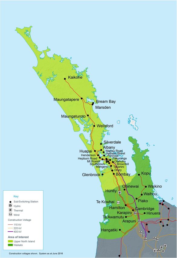
2.2 Region of interest
The region of interest is the Waikato and Upper North Island (UNI), being the 220 kV system
from Hamilton (HAM) north, and the 110 kV system from Arapuni (ARI) north.
This region is illustrated schematically in Figure 2-1 and geographically in Figure 2-2 below.
Figure 2-1: Illustration of Waikato and UNI transmission system (schematic)
BRB
220 kV 110 kV
UNI T5
KTA
MDN MDN
T6 KOE
HPI SVL
MPE
ALB T4 ALB MTO
WRD T7 WRD WEL KEN
HEN T5 HEN
HOB T1 HEP
SWN
PAK PEN T10 PEN LST ROS
T6
MNG
OTA T3
T5
TAK
T4
OTA SPLIT
G
L DRY T2
N
BOB WIR
HLY PAO
W W K
OHW H K P
U O U
TWH HAM T6 HAM
T9 K K HIN
P P
U O TMU
WKM WKM WKM ARI North
SFD
TMN
WAIKATO HTI
ONG
LEGEND
220 kV Lines Power Station On Load Tap Change Transformer
110 kV Lines Substation Static Capacitor
Dynamic Devices
Waikato and Upper North Island Voltage Management long-list consultation © Transpower New Zealand Limited 7
2016. All rights reserved.Chapter 2: Definitions Figure 2-2: Illustration of Waikato and UNI transmission system (geographic) Waikato and Upper North Island Voltage Management long-list consultation © Transpower New Zealand Limited 8 2016. All rights reserved.
Chapter 2: Definitions

2.3 Security standards
Transpower uses ‘deterministic’ security standards as a baseline for its system analysis:
N-1 and N-G-1.

N-1 refers to planning the system to be robust to a single failure (the “1”) in real time. That
is, planning for a system that can be operated such that supply can be maintained without
damaging transmission or connected assets, should an asset (e.g. a circuit or transformer)
fail.

N-G-1 refers to planning the system such that it                          Case study
can maintain N-1 security when a generator is
                                                                          On 16 May 2016 shortly before 6 pm
not available, for either a planned or unplanned                          Huntly unit 5 unexpectedly failed.
(forced) outage. For the Waikato and the UNI,                             Prior, the generation output was
since the thermal decommissionings, the largest                           around 375 MW. The forced outage
                                                                          lasted nearly 24 hours. The unit was
generation plant is Huntly unit 5, which would be
                                                                          then returned to service, ramping up
the ‘G’ for this region. An example of where a                            to around 200 MW until midday on the
generation failure has happened is presented in                           18th when it started ramping up to full
this case study.                                                          generation.

2.4 Expected and prudent peak demand forecasts
We plan our investments against a ‘prudent’ peak demand forecast. The prudent peak
demand forecasts represent a 10% probability of exceedance forecast in the first seven
years then assume growth rates equal to the expected forecast. As a result, the annual
growth in the prudent peak forecast is higher than the annual growth in the expected peak
forecast for the first seven years until 2022 inclusive. After that time, the two forecasts are
almost parallel. Prudent forecasts are sometimes referred to as ‘P90’ forecasts.

We conduct our economic analysis against an expected peak demand forecast. The
expected peak demand forecast can be interpreted as representing a 50% probability of
exceedance. It is often referred to as a ‘P50’ forecast.

In both the Waikato and the Upper North Island regions, the annual peaks have occurred in
the winter, and we assume on the basis of our modelling that this will continue.

Our peak demand forecast assumptions are presented in section 7.1.1.

Waikato and Upper North Island Voltage Management long-list consultation © Transpower New Zealand Limited   9
2016. All rights reserved.
Chapter 2: Definitions
2.5 Static and dynamic terminology
This section explains some technical terms used throughout this consultation paper.
Voltage stability refers to the ability of a power system to maintain steady voltages at all
busses in the system after being subjected to a disturbance, such as an event that
disconnects grid, load or generation equipment. Instability is due to the loss of operation
equilibrium, resulting in a progressive fall or rise of voltages of some busses.
Voltage stability on a power system requires both long-term or static stability, and short-term
or dynamic stability in the event of a fault on the system.
• We determine static voltage stability limits using a steady-state load-flow analysis
which captures the system behaviour as it settles from one steady-state equilibrium
to another. This method however cannot easily account for controls that depend on
the system’s time evolution, for which a dynamic simulation is performed.
• We determine dynamic voltage stability limits using dynamic analysis which captures
the response of preventive or corrective controls on the system (including generation
plant, reactive devices, protection relays and motor load) on the system during the
milliseconds and seconds after a disturbance, while the system is adjusting to its new
steady-state equilibrium.
Static reactive devices such as capacitor banks provide binary on/off response and are
generally used to support static voltage stability.
Dynamic reactive devices such as SVCs, STATCOMs and synchronous condensers provide
fast continuous response and are generally used to support dynamic voltage stability.
Waikato and Upper North Island Voltage Management long-list consultation © Transpower New Zealand Limited 10
2016. All rights reserved.Chapter 3: Need
3 Need
In 2015, the decommissioning of major generation plants in the Upper North Island (UNI) 1
was announced, including:
• 380 MW Otahuhu combined cycle unit (ceased generation in September 2015)
• 175 MW Southdown generation station (ceased generation at the end of December
2015)
• 500 MW Huntly units 1 and 2 (announced, to be withdrawn from the market in 2018).
The Integrated Transmission Plan 2015 2 highlighted grid backbone issues that could arise
following these retirements.
Transpower conducted a number of studies as both system operator and grid owner to
determine the impacts on the power system, covering different time horizons. A summary of
the results covering time horizons from 2018 are presented below in sections 3.1 and 3.2.
Since then, in late April 2016, Genesis Energy announced a delay in the decommissioning of
Huntly units 1 and 2 (the Rankine units) to the end of 2022 – this is discussed in section 3.3
below.
As some of the need (e.g. for generation security of supply) will be met by the market, and
some by Transpower, section 3.4 defines the scope of this project.
Finally, the assessed need, taking into account Genesis Energy’s decision and extending the
period of analysis, is presented in section 3.5.
Note that, normally, transmission needs would be signalled ahead through Transpower’s
transmission planning report. However these decommissionings were signalled after the last
2015 transmission planning report 3.
3.1 Grid owner’s findings assuming Rankine retirement in 2018
In April 2016 Transpower as grid owner published a report on Upper North Island operational
limits following Huntly Rankine unit retirements 4.
The purpose of these investigations was to define the issues. This involves computer-
modelling the North Island transmission system, taking the recent and proposed Upper North
Island generation decommissioning into account and projected load growth.
The system is tested by modelling a range of credible contingencies (failures of equipment
such as circuit outages). This testing is looking for system conditions where the
1
The region defined as the Upper North Island is defined in Section 2.2.
2
See www.transpower.co.nz/industry/regulatory-control-periods/rcp2/updates
3
See www.transpower.co.nz/resources/transmission-planning-report-2015.
4
See www.transpower.co.nz/upper-north-island-generation-decommissioning-report-and-appendices.
Waikato and Upper North Island Voltage Management long-list consultation © Transpower New Zealand Limited 11
2016. All rights reserved.Chapter 3: Need transmission system cannot supply the forecast load without constraints such as overloaded circuits, over or under-voltage and static/dynamic voltage instability. Following the announced decommissioning, the largest remaining single generator in the Upper North Island region will be Huntly unit 5, at 400 MW. This unit cannot be expected to have 100 per cent availability, so the system was tested for both a single credible contingency (N-1) as well as a single contingency with unit 5 out of service (N-G-1). The key findings were as follows: 3.1.1 Upper North Island reactive support - dynamic analysis Dynamic voltage stability limits are reduced by the removal of generation in the Upper North Island. The investigation found that post-decommissioning, the Upper North Island winter N-1 and N-G-1 voltage stability limits will be 2534 MW and 2219 MW respectively. This compares to the 2015 winter peak of 2150 MW, and the 2020 prudent peak load forecast of 2550 MW. This indicates that the power system will not be able to supply the peak Upper North Island load from 2020 if the last two Rankine units at Huntly are decommissioned. In addition, the results of this investigation indicate a possible voltage stability issue in the wider Hamilton area. 3.1.2 Upper North Island reactive support – load flow analysis Upper North Island static voltage stability limits may be exceeded when the announced Huntly generation decommissioning goes ahead. Insufficient dynamic voltage support (rather than static support) is expected to be the first constraint. 3.1.3 Thermal constraints between Whakamaru and Auckland The timing of thermal constraints between Whakamaru and Auckland depends on the timing and location of replacement generation. For example, new generation in the Wairakei ring area could create N-G-1 constraints immediately, however new generation in Taranaki will not create constraints between Whakamaru and Auckland in the short term (although it may create constraints outside this area). 3.1.4 Review of existing constraints south of Whakamaru The 110 kV Bunnythorpe–Mataroa circuit already limits the ability to supply the Upper North Island with existing generation from the Wellington and Taranaki regions. There is an investigation underway looking at solutions to this constraint. Even with the Bunnythorpe– Mataroa constraint resolved, thermal N-1 constraints south of Whakamaru will occur as soon as new generation is commissioned in Taranaki or the lower North Island, or HVDC capacity is increased, to replace generation being decommissioned. Waikato and Upper North Island Voltage Management long-list consultation © Transpower New Zealand Limited 12 2016. All rights reserved.
Chapter 3: Need

3.1.5        Waikato 110 kV issues

The Arapuni bus split will remain open in the interim, which is a reversal of our previous
intention to close this split in 2017. This investigation has gone beyond the Needs stage
because it was already an issue we were managing with a development plan 5 in place prior
to the generation decommissioning being announced.

3.1.6        High voltage management in the Upper North Island.

The management of high voltages in the Upper North Island is not greatly affected by the
announcement of the generation decommissioning. This is because it is a light-load issue,
which occurs when most generation is turned off anyway. However, our review of this issue
has indicated that there may be an economic need for further investment.

3.2 System operator’s findings assuming Rankine retirement in
    2018
In April 2016 Transpower as system operator published a report on Upper North Island
Operational Limits Following Huntly Rankine unit retirements 6. This report concludes that:
       •    If the Huntly Rankine units are decommissioned in 2018, operational measures may
            be required to manage both thermal capacity and voltage stability issues during
            contingency and outage conditions in the Upper North Island in winter.
       •    Although the Upper North Island power system will be more susceptible to risk
            exposures without the Rankine units, in 2018 the identified thermal capacity and
            voltage stability issues can be managed satisfactorily with transmission and
            generation assets currently in service and available to the market by utilising existing
            operational measures, however in 2019 and 2020 there is a risk that load
            management may be required at peak times.

3.3 Impact of delay in Rankine retirement
In late April 2016, Genesis announced that it “has entered into four-year bilateral commercial
arrangements with other market participants that will keep two Rankine Units available to the
end of 2022. The new contracts will cover the operational and capital costs of keeping the
units in the market.” 7

Meridian, one of the counterparties, describes its contract as “a four year swaption contract
with Genesis Energy to replace its current arrangement which expires on 31 December
2018. The new agreement begins on 1 January 2019 and ends on 31 December 2022. The

5
  See Transpower’s website for background information.
6
  See https://www.systemoperator.co.nz/activites/current-projects/impact-thermal-generator-decommissioning
7
  See www.nzx.com/companies/GNE/announcements/281406

Waikato and Upper North Island Voltage Management long-list consultation © Transpower New Zealand Limited   13
2016. All rights reserved.
Chapter 3: Need
structure continues to allow for 100 MW to be available year round, with an additional
50 MW available from 1 April to 31 October in each year of the contract.” 8
Transpower has discussed with Genesis Energy how these contracts will affect the operation
of the Huntly Rankine units from 2018 to 2022, and we appreciate Genesis’s assistance and
openness. While some details are confidential, we are confident from these discussions that
we can assume for planning purposes that from 2018 to 2022:
• Genesis will operate two Rankine units in the manner in which they are currently
operated, being offered into the market for MW and Mvar whenever commercially
appropriate
• Planned outages of Huntly units (including unit 5) will continue to be based on
ensuring that, between the Rankine units and unit 5, two units will be available
• Genesis will manage its coal and/or gas fuel contracts and stocks around these
availability targets
• Complete decommissioning of the Rankine units in December 2022
• If Tiwai announces that it will close prior to December 2022 (that date being the
closure, not the announcement), Genesis may retire the Rankine units earlier, but
also may keep them open if market conditions permit.
3.4 Scope of this project
As described above, it is expected that a mix of thermal and static and dynamic voltage
stability issues will arise from the thermal generation decommissionings coupled with
regional load growth.
The scope of this project is to consider solutions to the forecast static and dynamic voltage
stability issues.
Current Transpower projects with potential interactions with this project include:
• The installation and commissioning of a reactive power controller for the Upper North
Island (under the UNIDRS GUP approval)
• Transpower’s ongoing Demand Response programme 9.
• Thermal issues are currently the subject of an investigation within Transpower, which
may or may not result in a proposal to invest.
There are also some ongoing investigations and related projects, including:
• Investigations are underway to assess options for resolving central North Island
110 kV network constraints on the Bunnythorpe–Mataroa circuit, and retaining the
Arapuni bus split.
• Further investigations on the impact of new generation located in regions outside of
the Upper North Island, i.e. Whakamaru and south including central North Island,
8
See www.nzx.com/companies/MEL/announcements/281407
9
See www.transpower.co.nz/keeping-you-connected/demand-response.
Waikato and Upper North Island Voltage Management long-list consultation © Transpower New Zealand Limited 14
2016. All rights reserved.Chapter 3: Need
Taranaki, Wellington and the South Island, will be initiated when there is more
certainty on future generation investment location, size and timing.
• In addition, we may start an investigation into management of high voltages in the
Upper North Island in late 2016 or early 2017 depending on the preferred solution to
this project.
3.5 Need for investment
Following the removal of thermal generation, the load in the Upper North Island (UNI) will be
predominantly supplied from remote generation in the Wairakei ring, central North Island and
Taranaki areas. This increases the loading on transmission lines, making the UNI
susceptible to poor voltage performance. We have identified that dynamic voltage stability
after a major fault is the first limiting factor in supplying the UNI load (see section 3.1). The
studies also indicate a possible voltage stability issue in the wider Hamilton area. Further
work has been carried out extending the need assessment to include the Waikato region.
The findings are presented in the following section.
Due to the features of the New Zealand’s transmission network, the Waikato region (which
also connects to the main corridor of the 220 kV transmission circuits into the Auckland) –
and Northland regions have an impact to the need for voltage support. Both the dynamic
and static voltage stability limits in the UNI have reduced since the removal of generation,
and worsen when taking into account the load in the Waikato region (compared to the
voltage stability limits in section 3.1.1). For that reason, the investment need covered under
this project also looks into the reactive support requirement in the Waikato region.
3.5.1 Voltage stability limits
This section describes the voltage stability limits for the combined Waikato and Upper North
Island region.
Following the decommissioning of 380 MW Otahuhu combine cycle unit and 175 MW
Southdown generation station in 2015, the dynamic voltage stability load limit 10 in the UNI
reduces to around:
• 2,450 MW under N-G-1 security criteria. This is assuming the two Huntly Rankine
units are available providing full active and reactive power.
• 2,400 MW under N-G-1 security criteria if the two Huntly Rankine units are available
providing only the reactive support.
Post decommissioning of all Huntly Rankine units, the dynamic voltage stability load limits
further reduces to around:
• 2,350 MW under N-1 security criteria, and
• 2,100 MW under N-G-1 security criteria.
10
The load limits presented includes a 5% margin in accordance with standard international practice to account
for the uncertainties in assumptions.
Waikato and Upper North Island Voltage Management long-list consultation © Transpower New Zealand Limited 15
2016. All rights reserved.Chapter 3: Need
The above numbers are approximate because they are sensitive to the assumptions, and
the system operator may calculate and apply different limits at or closer to real-time.
Figure 3-1 shows the UNI voltage stability load limits plotted along with the 2015 winter peak
load and winter prudent peak demand forecast from 2016 to 2025. The worst case outage
for:
• N-1 is the loss of a 220 kV Pakuranga–Whakamaru circuit.
• N-G-1 is the loss of a 220 kV Pakuranga–Whakamaru circuit when Huntly unit 5 is
not available.
Figure 3-1: Upper North Island forecast annual peak (winter) and voltage stability limits
2800
2700 N-1
UNI demand and load limits
Annual peak MW (in winter)
2600
N-G-1 static
2500
2400 N-G-1 dynamic
2300
2200
2100
Two Huntly Rankine units in service Retired
2000
2015
2016
2017
2018
2019
2020
2021
2022
2023
2024
2025
In Figure 3-1, the:
• N-G-1 dynamic voltage stability limit is as described above
• N-G-1 static voltage stability limit is from the system operator’s analysis 11
• N-1 limit is as described above, also from the system operator’s analysis
• Expected (P50) and prudent (P90) forecasts are as presented in section 7.1.1.
11
From Upper North Island Operational Limits Following Huntly Rankine unit retirements, April 2016, available at
www.systemoperator.co.nz/activites/current-projects/impact-thermal-generator-decommissioning.
Waikato and Upper North Island Voltage Management long-list consultation © Transpower New Zealand Limited 16
2016. All rights reserved.Chapter 3: Need
3.5.2 Uncertainty
The N-G-1 static limit and the N-1 limit illustrated in Figure 3-1 included indicative confidence
bands indicating the range of uncertainty across three different generation dispatch
scenarios, which probably underestimate the actual degree of uncertainty. The N-G-1
dynamic voltage stability limit is represented by a single line because we have not quantified
the range of uncertainty in that limit. However, there is likely to be considerable uncertainty,
because it is sensitive not only to generation dispatch scenarios but also to motor load
assumptions (see section 7.1.3).
The P90 prudent forecast has by design a 10% chance of being exceeded in the first seven
years, and does not include allowance for the Electricity Authority’s proposed changes to the
TPM and ACOT charges which could materially raise peak demand (see section 7.1.2).
There is thus uncertainty in the winter 2021 need date indicated in Figure 3-1: indeed further
analysis could indicate that the static N-G-1 voltage stability limit is lower than the N-G-1
dynamic voltage stability limit. We intend to use the N-G-1 dynamic voltage limit binding in
winter 2021 as the need date for this project, but be cognisant of the reality that it could
change as we further our analysis and as demand trends become clearer.
3.5.3 Need date and quantum
Transpower’s analysis indicates that the power system will not be able to supply the peak
UNI load from winter 2021 even with two Rankine units available to provide active and
reactive power support under the N-G-1 contingent event. The gap between the prudent
load forecast and UNI load limit is in the order of 100 MW.
In addition, once the Rankine units retire, there is a much larger gap between the prudent
load forecast and the UNI load limit, in the order of 400 MW, and increasing,. Even under
the expected forecast the gap is over 200 MW and increasing. This need has to be met
before winter 2023.
To meet this need requires either:
• Generation investment at or north of Huntly
• Increased reactive support in the Waikato and/or UNI
• Reduced winter peak load in the UNI.
3.5.4 Voltage support requirement
To reliably supply the UNI peak load without significant local generation creates two issues
related to voltage support that must be satisfied:
• Firstly, there must be sufficient reactive power available in steady state in the UNI to
enable power to be delivered along the transmission lines from generators south of
there. Power flow in overhead transmission lines results in reactive power absorption
by the transmission lines, so this reactive power cannot all be provided from the
south without creating a significant voltage depression in the UNI.
Waikato and Upper North Island Voltage Management long-list consultation © Transpower New Zealand Limited 17
2016. All rights reserved.Chapter 3: Need
• Secondly, the dynamic reactive power available must be sufficient to meet all the
required contingent events.
To reliably supply the UNI at times of very light load creates the separate issue of the need
to reduce the capacitive reactive power (or add sources of inductive reactive power) during
steady state operation of the grid. This can be achieved by switching out capacitors, cable
circuits and/or lightly loaded overhead transmission lines. The outcome of the static and
dynamic voltage investigation within this project will impact the high voltage issue forecasted
at light load. We will assess the need to progress an investigation into the high voltage issue
once this project reaches a preferred solution.
Question 1 Do you agree with our assessment of need and project scope?
Are there any other issues or considerations relating to the need or scope
that we should incorporate into this project?
Waikato and Upper North Island Voltage Management long-list consultation © Transpower New Zealand Limited 18
2016. All rights reserved.Chapter 4: Long-list of components 4 Long-list of components In the absence of significant new generation in the region, a single asset is unlikely to provide a complete economic solution by itself. The preferred solution is expected to be a mix of assets, probably with sequenced introduction. For this reason we are referring to the long-list as a long-list of components, rather than our usual terminology of a long-list of options. The draft long-list of components is laid out below and summarised in Table 4-1. This draft long-list includes a wide range of possible components for contributing to meeting the need, including both transmission and non-transmission solutions. The need for investment, described in section 3 above, is such that while there are many components that could contribute to meeting the need for both static and dynamic voltage support, many are quite specific technologies. While the size of the expected need is known, the required size of each component asset in an optimal mix to meet that need is not. Indicative minimum sizes in Mvar are included here to give a lower bound on what is likely to be economic as part of a mix of investments. While we anticipate that the dynamic voltage stability constraint binds first in the Upper North Island, the poor voltage performance in the Waikato needs to be addressed too. We need static reactive devices in the Waikato, but that does not rule out having dynamic reactive devices there too. 4.1 Reactive power devices Non-transmission solutions for reactive power devices could be met through a voltage support grid support contract, discussed in section 5.2. 4.1.1 Conventional capacitor banks Conventional capacitor banks are grid connected and switched with circuit breakers. These are the least expensive form of voltage support but are normally used to provide static voltage support only. However, conventional capacitor banks can be dynamically switched with secondary circuit breakers which could boost reactive power output and speed up voltage recovery. A capacity per bank of around 50-100 Mvar at high transmission voltage level would likely be appropriate in the Waikato (around Hamilton) or in the UNI regions. Capacitor banks would require a control system, and would likely be controlled by a reactive power controller. Shunt capacitors can be connected at distribution level to correct power factors by providing reactive power near the inductive loads that required them, reducing the reactive power drawn from the grid. Waikato and Upper North Island Voltage Management long-list consultation © Transpower New Zealand Limited 19 2016. All rights reserved.
Chapter 4: Long-list of components

Transmission solution                                  Non-transmission solution
New capacitor(s) at Transpower                         Embedded in distribution networks, albeit that the
substation(s)                                          Code’s requirement for unity power factor would
                                                       require dispensations to be granted.

Capacitors do not usually provide the fast dynamic response required for sudden power
system events when a rapid response (milliseconds) is required to maintain voltage quality.
For these events, devices which respond dynamically are required. Generators,
synchronous condensers, thyristor switched capacitors (TSCs), static var compensators
(SVCs) and static synchronous compensators (STATCOMs) are all examples of such
devices.

4.1.2      Fast mechanically switched shunt capacitors and/or CAPS scheme

Both fast mechanically switched shunt capacitors and/or capacitor bank series group
shorting (CAPS) 12 schemes are potentially cheaper methods of supplying reactive power
dynamically. They are control scheme added to a shunt capacitor bank to switch in the bank
or boost additional reactive power capacity from a shunt capacitor bank. The additional
reactive power output provides additional temporary voltage support during which corrective
actions can be implemented.

Transmission solution                                  Non-transmission solution
New capacitor(s) at Transpower                         This solution will not address the issue.
substation(s)

4.1.3      Thyristor switched capacitor banks

Thyristor switched capacitor (TSC) banks are one component of static var compensators
(SVC, see below) but can also be installed separately when required. Thyristor switched
capacitor banks can respond very rapidly to changes in the power system. The speed of
operation is fast enough to provide the dynamic reactive support required, and TSC banks
can avoid the discharge requirements of circuit breaker switched capacitors. They will
typically require a dedicated transformer.

Transmission solution                                  Non-transmission solution
New capacitor(s) at Transpower                         This solution will not address the issue.
substation(s)

12
  The CAPS (capacitor bank series group shorting) scheme was developed by Bonneville Power Administration
(BPA) and implemented in its network. This is done by shorting several series groups of capacitor units, which
reduces the bank reactance, thereby increasing reactive power output.

Waikato and Upper North Island Voltage Management long-list consultation © Transpower New Zealand Limited   20
2016. All rights reserved.
Chapter 4: Long-list of components 4.1.4 Synchronous condensers A synchronous condenser is akin to a synchronous generation motor whose shaft is not connected but spins freely. The contribution of a synchronous condenser would vary by location – it would need to be at or north of Huntly. The minimum economic size is likely to be in the tens of Mvars, ideally in the 100-200 Mvar range. They would need to be connected directly to Transpower’s high voltage grid assets, embedding them in a distribution network would not meet the need. Transmission solution Non-transmission solution New synchronous Conversion of existing generation units (e.g. Southdown or condenser(s) at Huntly Rankine units), or new synchronous condenser(s) Transpower substation(s) connected at Transpower substation(s). Converted generation units could be contracted as a service through a grid support contract, or could be purchased and operated by Transpower. 4.1.5 STATCOM A static synchronous compensator (STATCOM) is a voltage regulating device based on a power electronics voltage-source converter, and can act as either a source or sink of reactive AC power. One or more STATCOMs would help, ideally each in the 100-150 Mvar range. For maximum effect they should be located in the Auckland region. STATCOMs are available up to around 33 kV. These can be grid connected via a transformer, but not embedded in a distribution network. Transmission solution Non-transmission solution New STATCOM(s) at Reactive support provided from modern wind farms that have Transpower substation(s) STATCOM-like behaviour. 4.1.6 SVC Static var compensators (SVCs) are also regulating devices based on power electronics and can provide fast-acting reactive power. SVCs generally require more land area (footprint) for the same sized STATCOM as they have large thyristor controlled reactors and capacitors, and in addition require passive harmonic filters. SVCs can be cheaper than the equivalent STATCOMs, but do not provide as much support at low voltages. SVCs need to be grid connected via a transformer, and are typically economically viable in the 100 Mvar plus range. For maximum effect they should be located in the Auckland region. Transmission solution Non-transmission solution Waikato and Upper North Island Voltage Management long-list consultation © Transpower New Zealand Limited 21 2016. All rights reserved.
Chapter 4: Long-list of components

New SVC(s) at                         Reactive support provided from modern wind farms that have
Transpower substation(s)              SVC-like behaviour.

4.1.7      Hybrid STATCOM/SVC

To provide fast dynamic response over a wider range while minimising both the cost and the
land requirements, manufacturers also now offer hybrid STATCOM/SVC solutions which
combine the two devices with a single control system.

Transmission solution                 Non-transmission solution
New hybrid                            Reactive support provided from modern wind farms that have
STATCOM/SVC(s) plant at               Hybrid STATCOM/SVC-like behaviour.
Transpower substation(s)

4.1.8      Hybrid STATCOM/battery

Hybrid STATCOM/battery plant is becoming available that combines the advantages of both
(see above and below).

Transmission solution                 Non-transmission solution
New hybrid                  None of which we are aware.
STATCOM/battery plant(s)
at Transpower substation(s)

4.1.9      Grid-sized battery storage

Large – multiple tens of MW – batteries, or battery banks or aggregations of that size, could
contribute through reducing net demand at peak or contingent times, in a similar manner to
demand response. They can also contribute dynamic reactive support.

Like STATCOMs, batteries use DC-AC inverters which may switch off at low voltages, which
could be an issue.

Transmission solution                 Non-transmission solution
Large grid-sized battery at           Distributed battery storage with appropriate aggregated
Transpower substation(s)              control system.

4.2 Other transmission assets
This section discusses draft long-list components that are grid assets and that we believe
have no non-transmission equivalents.

4.2.1      Series capacitors

Series capacitors are used primarily to obtain the desired load division among parallel lines
and to improve system stability. Series capacitors on the Brownhill–Whakamaru (BHL-

Waikato and Upper North Island Voltage Management long-list consultation © Transpower New Zealand Limited   22
2016. All rights reserved.
Chapter 4: Long-list of components

WKM) circuits would also improve the dynamic voltage stability in the UNI region (and would
reduce transmission losses).

4.2.2      Undergrounding circuits in the Auckland region

Adding cables provides additional capacitance on the network, with experience from the
North Auckland and Northland (NAaN) project suggesting that 10 km of cable could provide
around 40 Mvars. However, at low load there are limited circuits that can be switched out of
service to keep the voltage down, so reactors may need to be added when cables are
installed which limits or eliminates the positive benefit of the capacitance at high load.
Underground cabling would contribute to the static need only, and is expensive.

4.2.3      New line from generation centre to Auckland

This and the following three options for increasing grid capacity would assist in both static
and dynamic voltage support, and in easing thermal transfer limits into the Waikato and
Upper North Island.

A new line connecting generation centres from or through the Waikato into Huntly (e.g. from
Whakamaru to Huntly) or connecting into the Huntly–Stratford circuits would require a new
switching station to decrease impedance and hence improve the flow of Mvars.

4.2.4      Upgrade existing lines to reduce impedance

Impedance in the existing grid south of Huntly could be reduced also through upgrading
existing lines, such as duplexing the Otahuhu–Whakamaru circuits or upgrading the existing
duplex circuits to triplex or quad.

4.2.5      400 kV conversion

The 220 kV Brownhill–Whakamaru circuits, built under the North Island Grid Upgrade
(NIGU) project, are designed to be upgradeable to 400 kV. Series capacitors and more
cables would be required as well as 400/220 kV interconnecting transformers.

4.2.6      Grid reconfiguration

Reconfiguring the grid to reduce line length, or better sharing of load between circuits, would
reduce voltage drop and assist in meeting the need. One potential option is to build a
220 kV substation east of Hamilton on the Otahuhu–Whakamaru C line.

4.3 System operations

4.3.1      Use dynamic analysis to determine dynamic voltage stability limits
           operationally

The system operator currently determines static voltage stability limits in real time. It is likely
that, following the closure of a number of generating plants in the UNI, the dynamic limit may

Waikato and Upper North Island Voltage Management long-list consultation © Transpower New Zealand Limited   23
2016. All rights reserved.
Chapter 4: Long-list of components
be more constraining. Upgrading system operator tools, processes and systems would be
necessary to allow the system operator to perform dynamic analysis within operational
timeframes.
4.4 Market generation
Additional market generation in Huntly or north would help, both in reducing net MW demand
and in providing Mvar support. The minimum economic size is likely to be in the high tens to
hundreds of MW.
Market generation has, since market inception 13, been decided upon by the market on a
competitive and commercial basis. This remains the preferred means for additional market
generation in Huntly or north to occur.
The generation scenarios that we are assuming are described in section 7.2.3. We are
especially interested in any information on intentions for new market generation in Huntly or
north, which could affect our assumptions and scenarios.
Although pure market-driven investment is preferable, market generation could be
contracted under a market generation grid support contract. Transpower’s grid support
contract product design only allows contracting with market generation under precise
conditions, to avoid interfering with the market, as discussed in section 5.4.
Transpower also could build and own generation itself.
Embedded non-market generation is included in demand-side participation below.
Transmission solution Non-transmission solution
Transpower build and Market provides (preferred): market generation investment
ownership of generation changes our scenarios.
Market generation grid support contract.
4.5 Demand-side participation, including embedded generation
Dynamic voltage stability is caused by the re-acceleration of motors immediately after a
short circuit fault. To meet the need, the types of loads shed in the demand-side
participation (DSP) products for both pre- and post- contingent load shed in sections 4.5.2 to
4.5.4 must contain a high proportion of motor load (rather than resistive load). Reliable
embedded non-market generation would also be a contender.
4.5.1 DSP – uncontrolled
Increased uptake – on mass – of emerging technologies including solar photovoltaic (PV),
batteries and electric vehicles (EV) can affect both the net MW load and voltage profiles.
13
Since 1996, other than the brief government procurement and ownership of the Whirinaki power plant.
Waikato and Upper North Island Voltage Management long-list consultation © Transpower New Zealand Limited 24
2016. All rights reserved.Chapter 4: Long-list of components
We have endeavoured to incorporate the effect of such technologies in our demand
forecasts and generation scenarios.
4.5.2 DSP – pre-contingent load reduction
Demand response that is called ahead of need based on a forecast could help. This could
be called hours ahead of time (as in Transpower’s current Demand Response initiative 14) or
closer to real-time, say 15 minutes.
Transpower is currently determining how accurate the forecast would need to be to call
demand response with sufficient accuracy to meet the need, which will drive whether pre-
contingent demand response is a viable alternative, and if so what call horizon would be
adequate, and whether there are other perquisites to its operation, such as:
• an improved medium- or short-term load forecast
• the system operator basing voltage stability constraints on dynamic analysis (section
4.3.1)
• more reliable and resilient communications protocols
4.5.3 DSP – pre-contingent load cap
An alternative to a load reduction product described above is a load capping product that
would, for example, limit net load at one or more Auckland GXPs to an agreed amount.
Transpower could for example enter a grid support contract with a distribution company or
major load to cap its peak load to a certain level under certain conditions, with the
counterparty taking responsibility for managing that. An attractive feature of such an
approach would be that it could provide some insurance against the potential impact of
removing RCPD and ACOT, if that occurred (see section 7.1.2), by in effect rolling those
incentives and contracts into the grid support contract framework.
4.5.4 DSP – post-contingent
Alternatively, demand-response could be triggered immediately post-contingency. For a
voltage stability issue such as this need, it would have to be on very fast response relays
with adequate reliability, security and control: in other words, protection-grade equipment.
Such schemes are referred to generically as special protection schemes (SPS). We
envisage two options for triggering such a scheme:
• On voltage as ‘automatic under voltage load shedding’ or AUVLS. Designing and
programming a SPS to respond to voltage conditions in the UNI area to drop loads
post-contingency can be difficult and challenging as the system instability point could
occur at different voltages depending on system conditions.
• On predefined system and operating conditions, which while a proxy for voltage can
be easier to implement and monitor.
14
See the demand response page on Transpower’s website for more information.
Waikato and Upper North Island Voltage Management long-list consultation © Transpower New Zealand Limited 25
2016. All rights reserved.Chapter 4: Long-list of components
Question 2 Do you agree with our draft long-list of components?
If not, what components should we include or remove?
Waikato and Upper North Island Voltage Management long-list consultation © Transpower New Zealand Limited 26
2016. All rights reserved.Chapter 4: Long-list of components
Table 4-1: Draft long-list summary
Typical Typical
Indicative
duration of duration of Transmission Non transmission solution
Component Location component
construction consent solution (through GSC)
15 16,17 size
works process
4.1 Reactive power devices
4.1.1 Conventional capacitor banks 2-3 years 6 to 18 months Waikato and/or ~50-100 New plant(s) at Embedded in distribution
Upper North Mvar Transpower network, albeit that the Code’s
Island substation(s) requirement for unity power
factor would require
dispensations to be granted
4.1.2 Fast mechanically switched 2-3 years 6 to 18 months ~100 Mvar This solution will not address
shunt capacitors and/or CAPS the issue
scheme
4.1.3 Thyristor switched capacitor 2-3 years 6 to 18 months
banks
4.1.4 Synchronous condensers 3-5 years 6 to 18 months Huntly or north ~100-200 Conversion of existing
Mvar generation units, or new
plant(s) connected at
Transpower substation(s)
4.1.5 STATCOM 3-5 years 6 to 18 months Huntly or north, ~100-150 Reactive support provided from
15
The typical duration of construction works includes design, procurement and construction time for the discrete component only and is not site specific. It does not include
enabling activities such as support infrastructure, designations, property or consents, the durations of which are highly site specific and may be significant. Most development
plans will include multiple components from Table 4-1.
16
It could take several years to obtain the required consents for components that require work outside Transpower’s existing sites. There is significant uncertainty in any
estimate of the duration of the consent process as it is highly sensitive to the particular route chosen and the scale of work and access required.
17
While some design and procurement work can be undertaken in parallel with the consent process, we consider the total delivery time to be approximately the duration of
construction works plus the duration of the consenting process.
Waikato and Upper North Island Voltage Management long-list consultation © Transpower New Zealand Limited 2016. All rights reserved. 27You can also read