WM-E Term User Manual - WM-E3S Universal configuration tool for WM-E1S, WM-E2S, WM-E2SL
←
→
Page content transcription
If your browser does not render page correctly, please read the page content below
WM-E Term ®
               User Manual
       Universal configuration tool
   for WM-E1S ® , WM-E2S ® , WM-E2SL ® ,
                  WM-E3S ®
       electricity metering modems

______________________________________
                                                v1.88
                                           2021-01-20

                     1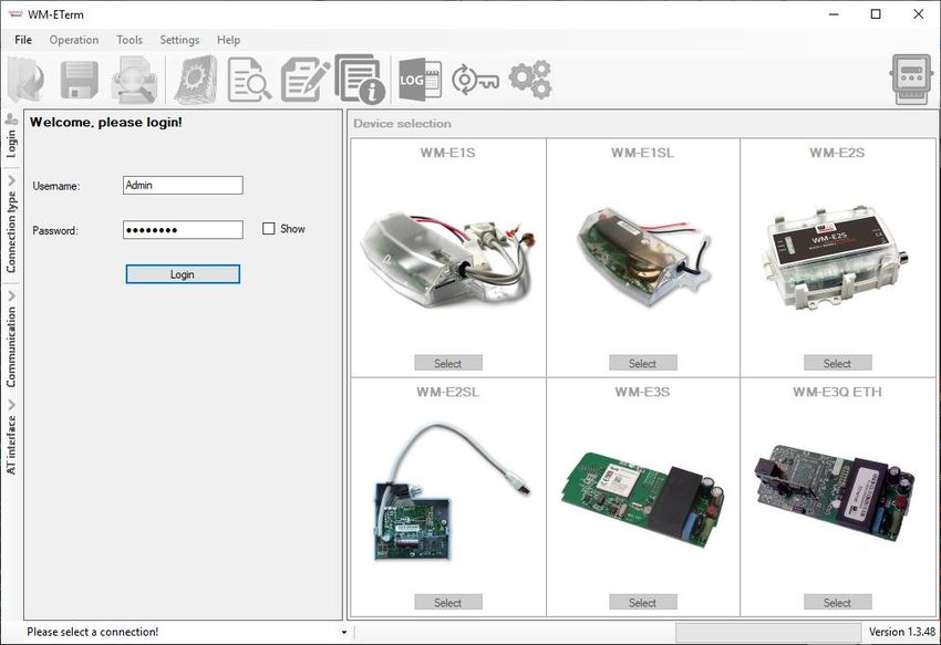
Document specifications
This documentation was made for the usage of the WM-E TERM® software.

The application is capable of configuring the WM-E1S®, WM-E2S®, WM-E2SL®, WM-E3S®
modem for connecting and readout data of the connected meter.

Document Version:        REV 1.88

Hardware Type/Version:   WM-E TERM®

Software Version:        V 1.3.48

Pages:                   79

Status:                  Final
Created:
                         2 May, 2017
Last Modified:
                         20 January, 2021

                                            2
Table of Contents
Chapter 1. Connecting to the meter ...................................................................... 5
1.1 Introduction ........................................................................................................................................ 5
1.2 Preparing ............................................................................................................................................ 5
1.3 Start the application, connect to the device ...................................................................................... 5
1.4 Setup the connection .......................................................................................................................... 7
1.5 Editing and Deletion of connection profile(s) .................................................................................. 14
1.6 Connect to the meter (Choose a connection) ................................................................................. 15
1.7 Device Information ........................................................................................................................... 16
1.8 Transparent mode (for Optical connection only) ............................................................................. 17
1.9 Using fixed and dynamical addresses .............................................................................................. 18
Chapter 2. Configuration .................................................................................... 19
2.1 Parameter readout (from the meter) ............................................................................................... 19
2.2 Saving the parameters...................................................................................................................... 23
2.3 Loading the saved parameters ......................................................................................................... 24
2.4 Mass configuration (for multiply devices) ....................................................................................... 25
Chapter 3. Parameter group settings .................................................................. 27
3.1 APN settings ...................................................................................................................................... 27
3.2 Wireless settings............................................................................................................................... 29
3.3 Mobile network settings ................................................................................................................... 30
3.4 Watchdog settings ............................................................................................................................ 32
3.5 Calendar settings (Time zone) ......................................................................................................... 34
3.6 Serial data transmission (meter → modem) settings ................................................................... 35
3.7 IEC server settings (AMM/IEC) ........................................................................................................ 37
3.8 “LastGASP” push notification alert settings .................................................................................... 39
3.9 RS485/DCD meter settings .............................................................................................................. 41
3.10 AMM/DLMS settings ....................................................................................................................... 43
3.11 M-Bus settings ................................................................................................................................ 45
3.12 Secondary transparent settings (WM-E3S MBUS) ......................................................................... 47
3.13 P1 Customer Interface settings ..................................................................................................... 48
3.14 SNMP parameter settings ............................................................................................................... 49
3.15 Device Manager settings ................................................................................................................ 51
3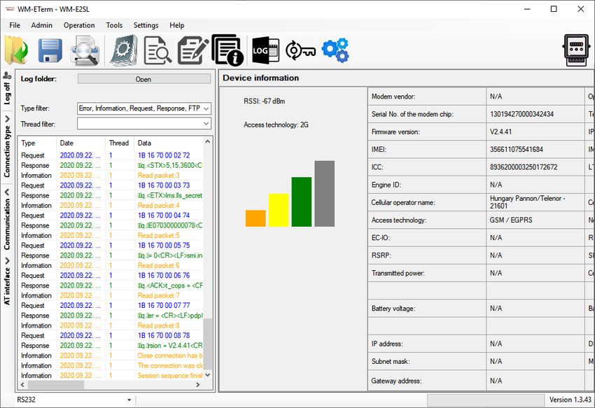
Chapter 4. Firmware updates .............................................................................. 54
4.1 Single firmware update ................................................................................................................... 54

4.2 Mass firmware update (multiply uploads) ....................................................................................... 55

4.3 Single firmware update from IEC to DLMS ..................................................................................... 58

4.4 Mass firmware update from IEC to DLMS (multiply uploads) ......................................................... 59

4.5 Single Telit firmware update ........................................................................................................... 61

4.6 Mass Telit firmware update ............................................................................................................. 62

4.7 Single bootloader update ................................................................................................................ 64

4.8 About the certifications ................................................................................................................... 64

4.9 CA Certificate handle ....................................................................................................................... 64

4.10 Certificate handle ........................................................................................................................... 67

4.11 CRL handle ..................................................................................................................................... 68

4.12 CSR handle ..................................................................................................................................... 69

4.13 Status Read ..................................................................................................................................... 70

4.14 AES key import ............................................................................................................................... 71

4.15 Connection import .......................................................................................................................... 72

Chapter 5. Other features .................................................................................. 73
5.1 User management ............................................................................................................................. 73

5.2 Event log ........................................................................................................................................... 74

5.3 Check modem communication ........................................................................................................ 74

5.4 Ping host .......................................................................................................................................... 75

5.5 AT commands ................................................................................................................................... 76

5.6 Print ................................................................................................................................................... 77

5.7 General settings ................................................................................................................................ 77

5.8 Password change .............................................................................................................................. 78

5.9 Configuring the LED settings (optional) .......................................................................................... 78

                                                                                 4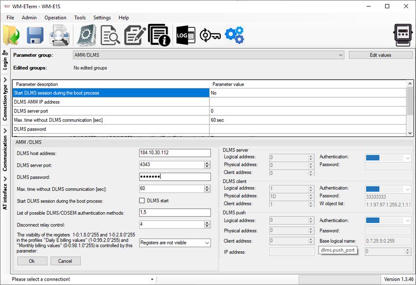
1. Connecting to the meter
1.1 Introduction

The WM-E Term® application is capable of configuring the WM-E2S®, WM-E2S® modems
for receiving communication from the meter. The configuration can be performed through
RS232 compatible connection of the modem, or by remote TCP connection.

After the configuration, the modem can initiate RS232/RS485 data connection with the
connected meter.

Please, follow the next steps for configuring the connection of the communication modem
(CM) and the meter system.

1.2 Preparing

1. The software can be used on Microsoft® Windows® 7 / 8 / 10 operating systems.

2. Microsoft® .Net Framework v4 must be installed on your computer. In case of missing this
component, you have to install it after having downloaded it from the manufacturer’s website:
https://www.microsoft.com/en-us/download/details.aspx?id=30653
3. You have to own administrator privileges for the directory, where running the program.

1.3 Start the application, connect to the device

1. Connect the optical head properly to the meter. Then connect it to the USB port of the
computer. Connect to the modem through the reqiured interface.

2. Download WM-E Term Appendix document by the link, which can help the configuration.
https://www.m2mserver.com/m2m-downloads/WM-E-TERM_Appendix_V1_00.pdf

3. Download the WM-E TERM® configuration software to your computer by using this link:
https://www.m2mserver.com/m2m-downloads/WM-ETerm_v1_3_48.ZIP

                                             5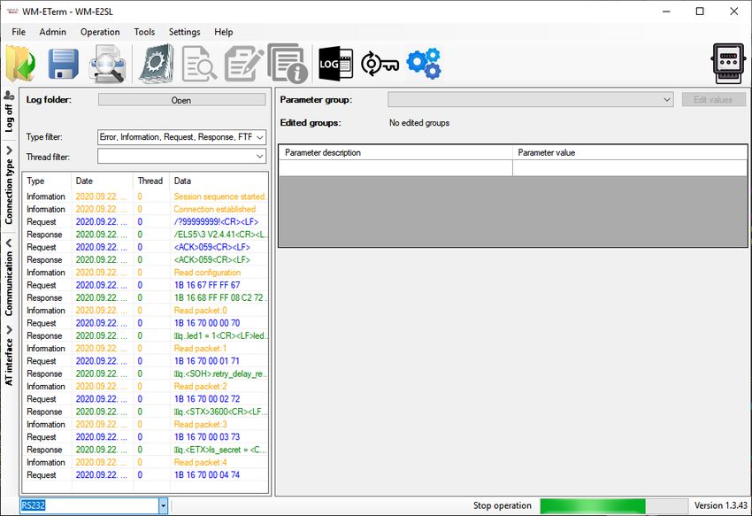
4. Unpack the .zip file into a directory and execute the WM-ETerm.exe file and the following
application screen appears.
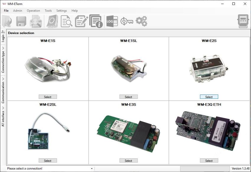
5. Define the login data to enter into the configuration software.
Default Username: Admin Default Password: 12345678
6. Select the metering modem type for settings – according to the currently used model.
6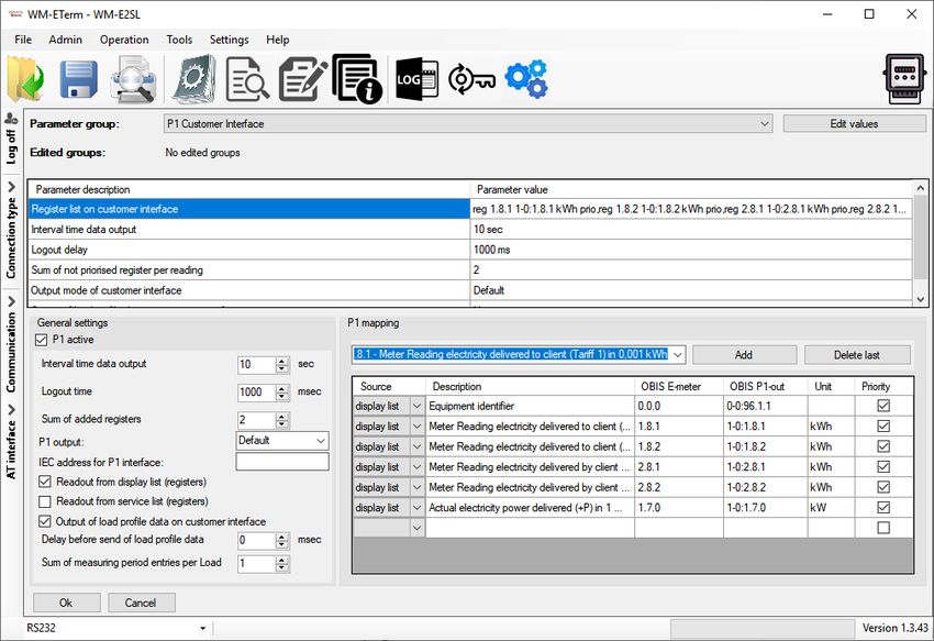
7. In the program window, you will find
icons and menu items for performing
settings, operation.

                                                     On the left side of the screen, the
                                                     navigation buttons will help you to
connect and check the communication.
At the bottom of the screen, on the lef hand side, you can connect with a pre-configured
profile to the modem (by selection).

1.4 Setup the connection

1. Configure the modem to the relevant interface. First you have to define at least one
connection profile. You can make four different type of connections: Optical, Serial, TCP/IP,
Modem.

2. Choose the Connection type on the left side of the screen, then choose an interface
regarding the required type of connection (Modem/TCP-IP/Serial/Optical).

Serial connection:
   1. Make serial RS232 connection between the modem and your computer (you should use
       RS485-RS232 adapter also or in case of using in case of WM-E2S® model RJ45
       connection, you have to use the RJ45-USB adapter).

   2. On the left-side of the screen click on the Connection type and choose the Serial
       interface.

   3. Add a name for the profile at the New connection field.

   4. Push the Create button, and in an another window the connection settings will appear.

   5. Add a name to the New connection field.

   6. Push the Create button and a new window will appear with connection parameters.

                                             7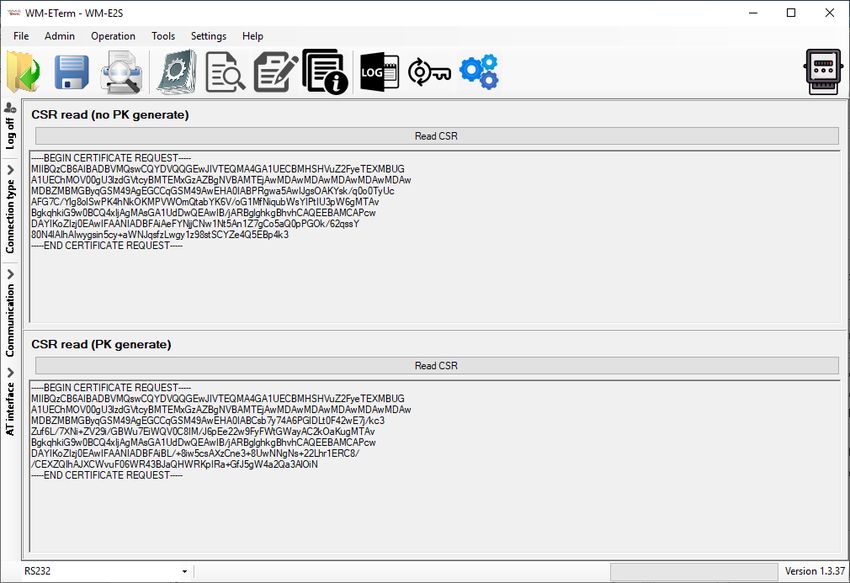
7. In the connection window you can define the connection profile parameters.

8. You can add the Password, the IEC address of the SIM card, and you can require the
communication to be logged (Communication log).

9. It is obligatory to setup the connection parameters: as COM port according to the available
serial/USB port, the dataspeed (Baud rate), and the Data format (e.g. 8,N,1).

10. You can Switch baud rate during the firmware by enabling the Switch enable option
and choosing a baud rate from the list. This will be valid for the fw update period.

11. You can define an AES key for the connection if you want. You can also declare the IMEI
number (metering modem’s module identifier) to guarantee that the connection is valid only
for the relevant hardware (the modem which has the IMEI).

                                               8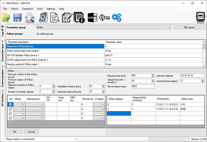
13. When you have finished, click on the Save button to save the connection profile.

Optical profile:
1. Make the optical connection between the meter and your computer (connect the optical
   USB cable to your computer and the opto-head to the meter).

2. On the left-side of the screen click on the Connection type and choose the Optical
   interface.

3. Add a name for the profile at the New connection field.

4. Push the Create button, and in an another window the connection settings will appear –
   similar to what was described at the serial connection.

5. Define the COM port, the Baud rate and the Data format values – as for the serial
   connection.

                                              9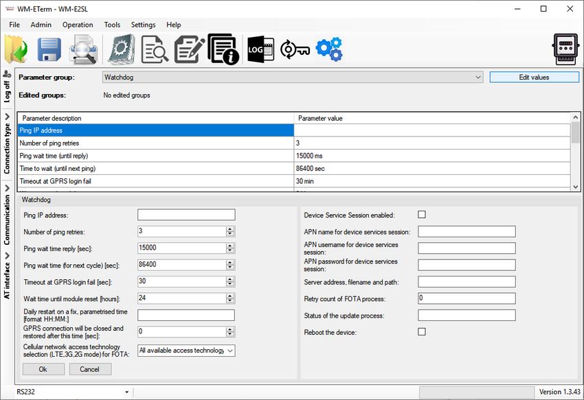
6. You can enable Always set transparent mode by its check box – for performing
   transparent communication between the IP address and the metering modem.

7. If you have communication issues by transparent communication, you can refine the
   settings by checking in the Use only 256 bytes packet option.

8. If it is necessary to use a secured IEC connection, you can add IEC password and the
   IEC address and a Communication password.
   (You can see and check the written password by the Show option.)

9. You can define an AES key for the connection if you want. You can also insert the IMEI
   number (metering modem’s module identifier) to guarantee that the connection is valid
   only for the relevant hardware (the modem which has the IMEI).

10. Push then the Save button to save the profile settings.

                                             10
11. When connecting by choosing the Parameters Read icon, on the next screen, add the
Parametrizing Password according to the meter information, Push then OK for the
connection.
12. The modem then reads out the data from the meter after connecting.
TCP/IP profile:
1. You need to know the IP address of the SIM card for connection and the pre-configured
port number to setup the TCP/IP settings.
2. On the left-side of the screen click on the Connection type and choose the TCP/IP
interface.
3. Add a name for the profile at the New connection field.
4. Push the Create button, and in another window the connection settings will appear –
similar to what was described at the serial connection.
115. Define the IP address o the connected SIM card and the Port for the connection.
6. You can define an AES key for the connection if you want. You can also insert the IMEI
number (metering modem’s module identifier) to guarantee that the connection is valid
only for the relevant hardware (the modem which has the IMEI).
7. If it is necessary to use a secured IEC connection, you can add IEC password and the
IEC address and a Communication password.
(You can see and check the written password by the Show option.)
8. Push then the Save button to save the profile settings.
Modem type:
1. On the left-side of the screen click on the Connection type and choose the Modem
interface.
2. Define a name to the profile at the New connection field.
123. Push the Create button, and in another window the connection settings will appear –
similar to what was described at the serial connection.
4. If it is necessary to use a secured IEC connection, you can add IEC password and the
IEC address and a Communication password.
(You can see and check the written password by the Show option.)
5. Define then the COM port, the Baud rate values and select a Data format type.
6. Add the Phone number* of the modem (SIM card’s phone call number).
*The first part is the prefix – it is not obligatory to be used.
The phone number is the second part, which can contain special (command) characters,
if you enabled the Also not numeric option.
137. Create a New Modem type. Some new parameters will then be listed at the bottom side
of the screen.
8. Hereby, add the Connection name and the modem Initialization command.
9. Select the bearer service type, and add the Dial command
10. In case of configuring a Modem type you can define the modems here (e.g. analog,
ADSL, etc.), or you can edit or delete a registered one.
You can define the Initialization command for the connecting modem.
Here you can configure further modem types also, use a Bearer service and define the
Dial command.
11. For storing the Modem type parameters and the connection type, push the Save modem
type button.
12. When you have finished the settings, push the Save button to save the connection profile.
1.5 Editing and Deletion of (a) connection profile(s)
1. You can delete the unnecessary connection profiles by choosing the Connection type
button on the left edge of the screen.
2. Choose an Existing connection at the connection selection part and the relevant settings
will be loaded to the right part of the screen.
3. Choose then Edit and you can modify the existing profile settings.
(You can, of course Delete also a stored connection profile).
141.6 Connect to the meter - Choose a connection
Important!
By the previous settings you have created the connection profile, but the configured
connection profile will NOT be automatically selected. You have to choose a connection profile
manually at the bottom of the screen to connect to the modem before any operation!
1. Once the connection profile has been chosen below, choose the Parameters Read
icon to readout the data from the meter.
2. All parameter values will then be read out from the meter and visible by selecting a
parameter group.
151.7 Device Information
After connecting to the modem, you can check the device current status by the icon (or
choose the Operation / Device Information view menu item).
Here, the modem type and identifiers, modem firmware and device firmware version as
identifiers are listed.
The current connection settings are listed here, as modem and firmware indentifiers, cellular
network provider code and operator name, available network and access technology. The
main important part can be seen on the left at the RSSI value and the Access technology
– as it is displayed with colour coloums, too.
(If the IP address is filled, that means that the device is currently communicating properly on
the cellular network.)
161.8 Transparent mode (for Optical type connection)
In case of using Optical connection, there is an End Transparent mode button at the
bottom of the screen. You can switch this mode on/off and control the meter to allow or
disable the transparent mode for the connecting metering modem.
Important!
The WM-E Term will switch off the Transparent mode after 15 minutes, then the button will
disappear. If you cannot connect to the meter, try to reconnect again and switch again the
button.
171.9 Using fixed and dynamical IP addresses
The modem can receive dynamic IP addresses - which are given by the GPRS/3G/4G
network provider’s DHCP service - and use them thanks to the APN settings and is able to
receive and transmit data through the network. It can also use fixed public IP and fixed
private IP addresses of the GPRS/3G/4G services during data call, transmission and data
exchange.
After performing the proper APN settings, you can check the given IP address of the
network provider, when connecting to the modem via the serial link.
At the Log communication tab on the left edge of the screen you can see the log for
checking the current IP address or use the Operation menu / Device Information
icon.
18Chapter 2. Configuration
2.1 Parameter readout (from the meter)
1. Open the Parameters read icon to read out the parameters of the meter.
2. This will initiate the connection of the modem in the background via the required
connection profile. The program tries to readout the parameters, which can be checked
by the progress indicator on the righ-bottom side of the screen.
3. You can check the connection any time by the Connection button on the left-side. Then
the current modem communication messages, commands and answers will be listed on
the left side of the screen.
(If you want to cancel the readout and the connection you can Stop operation.)
4. When the connection is succesful, the connection successful message appears. (In case of
a connection failure the error message will also appear here.)
5. The WM-E Term then loads the listed and read out parameter values.
196. Confirm the readout process by pushing the OK button – on the left.
7. At the top of the settings, the available parameter groups and
its listed parameters can be seen. This is where you can choose
another Parameter group by its button.
The available parameter groups depend on the currently used
metering modem model and the used firmware.
208. After loading the parameters at the top of the screen, you will then see the readout
parameters and its values - at the bottom.
Choosable parameter groups:
• AMM (IEC) – Data push, Event push (SMS messages*, LastGASP*) and EI client
• AMM/DLMS – DLMS server settings
• APN – APN zone settings (for the SIM card)
• M2M – GPRS connection settings
• Watchdog – GPRS Watchdog settings
• Mobile Network – Mobile network settings
• Calendar – Calendar settings and time zone (daylight) settings
• Standard meter interface – Date format, identifiers, LED operation settings
• Transp./NTA – serial data transmitting settings (transparent mode, etc.)
• RS485 meter interface –for RS485 meter connection settings
• Secondary transparent settings – configure a second communication channel
• Device Manger – some models and firmware versions allow the Device Manager®
software connection
• M-Bus*** – M-Bus and channel, readout register settings – only available for in
case of WM-E3S®, WM-E3S CI® (customer interface) and WM-E3S CI R® (relay)
models
• P1 Customer Interface*** – Customer interface settings (Load profile, meter
data, service list, register values) – available only for in case of WM-E3S®, WM-
E3S CI® (customer interface) and WM-E3S CI R® (relay) versions!
• Network Protocols - the SNMP parameter readout and settings for the SNMP
Manager compatibility (available for some WM-E2SL® (Landis & Gyr® connected)
type meters only)
• Ethernet*** – Ethernet interface, available only for WM-E3S®, WM-E3S CI®
and AM322® versions!
*Available if the modem PCB has a supercapacitor part.
9. By pushing the Parameter reads icon (menu item) you can repeat the whole readout,
anytime – when it is necessary or you want to test the modified settings (later).
2110. To edit the parameters, push the Edit values button to the right from the Parameter
group.
11. You will then see the parameter values listed, and you can modify them.
12. If you want to change another Parameter group, you have to push the Edit values
button again.
13. When you have modified the required parameters, push the OK button to record the
settings. Note that the settings will NOT be saved automatically or sent to the meter!
14. To send/write parameters to the modem, you have to push the Parameters write
icon.
15. The whole whole parameter list and the values will then be sent to the modem. The right
bottom progress indicator will show the percentage of the writing.
2216. A success message will then appear. Push the OK button
to continue.
Important!
After the parameter writing/sending, the modem will be
disconnected and it will be rebooting, then operating
according to the new settings.
Until the end of the restart process and the proper operation
status, it takes about 2-3 minutes. During this period you
cannot access the meter.
Please wait, while the modem and the meter will be
available again!
232.2 Saving the parameters
Open the File menu Save item to save the currently modified configuration (into a .CFG
extension file).
2.3 Loading the saved parameters
1. When you already have a previously saved and prepared configuration, you can open it
from the File menu by the Open item.
2. Browse the required configuration file (with .CFG extension) and push the Open button.
3. The program will then load the parameters, and you can write the parameters to the
modem/meter as it was described before.
4. For the editing, choose a Parameter Group from the drop-down sub menu, the stored
parameters will be listed.
245. By the Edit values button you can edit or change the stored parameters.
6. Push the OK button after the modification.
7. You can also save these settings to an another configuration file (.CFG).
Important!
By this saving, the modified parameters will not be automatically sent/written to the modem.
You have to send the parameters to the modem directly - choose the Parameters write button
for the sending of the parameters!
2.4 Mass configuration (for multiple devices)
You can use this feature for the quick parameter configuration of multiple modems.
1. Choose the Tools / Mass Configuration item from the menu.
2. Push the Browse button to select a mass
configuration file (*.CSV extension)
*The mass configuration CSV file must be
created by the Customer.
3. The requested list is loaded. You can Select
a default modem type.
You can add items or modify the settings.
4. The program will Then connect through the
modem profile when choosing the mass update – according to the modem profile settings.
Attention! Note that the new configuration will be available only after the mass configuration
file upload process is finished.
255. Push the Start update button to begin the multiple modem configuration. The update will
be valid for the listed modems.
The configuration process will be performed one by one (entry to entry) in sequence order.
6. The current status of the configuration refresh method will be shown at the progress bar.
Attention!
Please, be careful! The modem has several firmware types. Therefore, always ask our sales
team about the proper firmware version.
Please note, when updating the modem by a firmware, the current modem configuration
settings will be overriden – if they existed before the mass configuration process.
7. At the end of the parameter configuration upload process, the modems will restart and will
be using the new parameter settings.
26Chapter 3. Parameter settings
Here you will find the minimal and recommended settings of the meter device for the proper
data connection, mobile network communication and operation.
Read out the parameters of the modem with the Parameter Read icon.
When the readout process is finished, choose a Parameter group by the next listed hints
and following steps. After this stage, you have to send the parameters to the modem – see
later.
3.1 APN settings
1. Choose the APN group.
2. Push the Edit values button, and the relevant parameters and their values will be
listed.
3. At the bottom side of the screen fill in the following fields:
- APN Name – here you have to add the APN zone name according to the modem
SIM card (ask your Mobile Operator).
274. Add the the APN Username according the SIM by the mobile operator requirements.
5. Fill the APN Password if the SIM card uses a password for the APN access.
(If the SIM does not have an APN Username or APN Password, then leave these
fields blank or leave these fields on the replacement xxxxxxx).
Important! The module and the SIM card uses the PIN code specified in the "Mobile
network" parameter group when connecting.
6. If the modem restarts due to an incorrect configuration, it is possible to access it with
a CSD call. Its operation can be fine-tuned by setting the PDP Connection Delay
value. There you can add a delay (value in minutes) – the parameter can be set
between 3 and 255)
The handle of the PDP feature is the following:
• If the modem needs to be restarted for the 1st time because it could not connect
to the network and did not receive an IP address, there is no change, there will be
no extra delay added.
• If the modem has been restarted for 2nd time because you have not received an
IP address, then the device will wait 1 minute more before the restart to allow more
time to connect through the CSD.
• If the modem has been restarted for 3rd time because you have not received an IP
address, the device will wait 2 minutes before restart to allow even more time to
connect to the CSD.
• If the modem has been restarted for 4th time because you still have not received
an IP address, the device will wait for the amount of time you have specified at the
PDP Connection Delay parameter to allow more time for the CSD to connect
before restart.
• If the modem has been restarted for 5th time because you have not received an IP
address, the cycle will start over and the modem will not wait to restart… (according
to point 1)
6. Push the OK button and continue with the next part.
283.2 Wireless settings
1. Choose the M2M group for the cellular communication settings (2G, 3G, 4G, etc).
2. Push the Edit values button, and the relevant parameters and their values will be
listed.
3. At the bottom side of the screen, fill in the following fields:
- GPRS always ON – check in the field if it was empty (it will always be online)
- or choose the Connection timer – only if you are not using the GPRS always ON
option (when it is disabled), then Start GPRS connection will be enabled and you
can here define the modem operation period (as HH:MM:SS).
4. Encryption password via MD5 algorithm – You can ask for encryption of the
password via MD5 algorithm. Values: 0 = false, 1 = true
5. Additional delay time interval - in case of using "push" to give some delay for build-
up the connection. Value in seconds.
296. Hold time of GPRS connection - When there is no available GPRS connection, after
the defined time (in seconds) will try to reconnect the GPRS connection. Value in
seconds.
Note, that the modem uses the default nr. 9000 port for communication and the
port nr. 9001 for configuration and firmware refresh.
7. Here you can define the Port for the transparent (IEC) meter readout.
8. To define a different port for Port for downloading the config and firmware
refresh.
9. Select the AES-256 CBC encryption if you want and the AES-256 key for
download config and firmware.
10. You can also configure the Number of GPRS connection attempts until module
reset.
11. There are presetend some refine settings to define as Time between GPRS
connection attempts (in seconds) - if the PDP context activation was not successfull,
it will delay the reconnection according to the listing.
12. The Waiting time until next try field – is not implemented yet.
13. Push the OK button and continue with the next part.
3.3 Mobile network settings
1. Choose the Mobile network group for editing the cellular connection parameters.
2. Push the Edit values button, and the relevant parameters and their values will be
listed.
303. At the bottom side of the screen fill in the following fields:
- SIM PIN code – check in the field if the SIM card that you are using needs a PIN
code and fill in the code here
- You can add a Password for CSD call
- You can define the Number of rings before accept call (CSD)
- Cellular band – here you can define the mobile network and connection type (2G,
3G, LTE, and you can choose the option for the fallback* feature) for the modem
communication
31*Fallback: in case of outage of the
primary selected network (e.g.
LTE), the modem will switch to the
fallback band (e.g. 2G or 3G) and
will be operating further. When the
primary band will again be available,
the modem will switch back to the
main channel (e.g. to the LTE).
Attention! In case of using a 4G modem, if you have selected the All available
access technology, and despite of the selection the module still not access the 4G
network, choose the LTE with fallback to 2G option and save the settings. Then
check that the modem already connected to the 4G or not.
- At the Type of call field you can define Data, Fax or Voice mode. We suggest you
to use the Data option here.
- Answer incoming voice calls as data calls (CSD) if set to true. Ingore voice
calls otherwise. Here you can enable the CSD transformation of voice calls.
- Provider selection mode (roaming) – only if you attempt to define a dedicated
mobile network to use. The selection list is provided by the international mobile
operators.
The connection method can be Manual or Automatic.
Here you can add, delete or define the selection mode.
4. Push the OK button and continue with the next part.
323.4 Watchdog settings (monitoring the modem operation and
availability)
The device is able to perform manual/auto reboot with the following options configurable from
both the configuration program (WM-E Term) and SNMP. You can configure here the following
reboot options:
• Auto reboot to be disabled (configurable)
• Manual reboot (caused by any configuration modification)
• Auto reboot will run periodically based on a configurable timer which can be set up
to 24 hours (configurable and can be scheduled)
The auto reboot via watchdog timer will monitor 'keep alive' message coming from the CPU
at predetermined intervals. If the watchdog timer stops receiving the 'keep alive' message
from the CPU, the watchdog timer will initiate a reboot. The watchdog feature is running
independently from the CPU.
1. Choose the Watchdog group and push the Edit values button, and the relevant
parameters and their values are listed.
332. At the bottom side of the screen fill in the following fields:
- Ping IP address – add an IP address which can be accessed from the IP zone of
the SIM card. This will be used for continuous checking of the network availability.
You can define Number of ping-retries here and Ping wait time reply and the
Ping wait-time (for next cycle) in msec value.
3. GPRS login error timeout [sec]: if login is unsuccesful during the time specified
herein, the modem will not translate it as an error, and login will only fail after the set
time elapsed (value in seconds).
4. Wait time until module reset – it can also expressed in hours.
5. Use the Daily restart on a fix, parameterised time – if you attempt to define a
daily restart interval for the device - add the HHMM value of the time of the device
restart. Leave it empty if you do not allow the device to restart every day.
6. GPRS connection closed and restored after this time (sec) - If ping is
configured, you can specify the time (in seconds) between ping attempts.
Recommended values: 900, 7200
7. The device has also the ability to manually force to refresh the firmware remotely
(FOTA) by selecting only the GPRS or only 3G or only the LTE 4G standard. Check the
Cellular Network Access Technology selection (LTE, 3G, 2G mode) for FOTA
field’s value and choose the required option here.
8. You can enable the remote firmware refresh (FOTA) service by the Device Service
Session enabled checkbox.
Here you can add APN name and APN username, APN password and Server
address, path and filename for the session.
9. The Retry count of FOTA process means the number of remote firmware upgrade
retries – in case of FOTA progress.
10. At the Status of the update process you can get a message for the device’s current
34FOTA status.
11. If you want to reboot the device enable the Reboot checkbox – only implemented in
some special firmware versions – ask us!
12. Push the OK button and continue with the next part.
3.5 Calendar settings
1. Choose the Calendar group and push the Edit values button, and the relevant
parameters and their values will be listed.
2. Here you can enable the Switch daylight saving time – if you wish to use this
feature (using the annual daylight saving time as standard), then check the box, in any
other cases leave it empty.
353. You can also define the type of the time correction of the daylight saving by choosing
one of the possible radio buttons: EU standard, Standard time, Daylight saving
time.
If you’ll select the Standard time or Daylight saving time option, further data should be
defines as Month, Day and Time. Then you shoudld have to push to the Set date
button.
4. You can also use Offset daylight saving time (in minutes) or Deviation of local
time to GMT (in minutes) for the time synchronisation regarding the local needs and
habits.
5. Push the OK button and continue with the next part.
3.6 Serial data transmission meter→modem settings (Transp./NTA)
1. Choose the Transp./NTA group and push the Edit values button, and the relevant
parameters and their values will be listed.
2. You can choose the Multi-utility mode (DLMS active) – here you can define the
Transparent mode (of data transmitting) or the Multi-utility mode (not implemented
yet).
3. Then the Meter port baud rate (for transparent mode and meter reading) can
be also configured – define the serial data baud rate (baud) for the connection. The
default and recommended value is 9600 baud.
4. Fixed 8N1 data format at the meter – can be selected if you want.
5. You can use TLS protocol encryption* (between the modem and the meter), by choosing
the Transparent mode at TLS enable option.
6. You can then insert the Transparent mode certificate bank number and
Transparent CA certificate bank number here.
36(The bank value „0” means the default certificate used by the firmware, or you can
choose the „1” which means that the uploaded certificate will be used. You can upload
the certification file from the Tools menu, and choose the CA certificate or normal
certificate related menu item for the upload.)
7. You can also configure the Transparent mode certificate verify mode (Possible
values: Not / Optional / Mandatory).
8. Push the OK button and continue with the next part.
3.7 IEC server settings (AMM IEC)
1. Choose the AMM (IEC) group for meter connection settings.
2. Push the Edit values button, and the relevant parameters and their values will be
listed.
373. IP Address (AMM (IEC)) – here you can define the remote server’s IP address where
the data will be transmitted through the wireless network
4. Server port (AMM (IEC)) – AMM (EIServer) port (ftp client port), define the port
number of the server IP.
5. Auto register – Automatic registration to the address - checkbox. In case of data
push send automatically or not (Values: 0 = false, 1 = true).
6. Poll interval fast (not deployed) – Value of Poll interval fast (not deployed) in
seconds.
7. Poll-interval slow (deployed) – Value of Poll-interval slow (deployed) in seconds.
388. Define the EI client TCP keep alive – Keeps the EI client connection alive for the
defined time range – value in minutes.
9. EI Client username for the connection IP address, and EI Client password is also
also required, fill the fields, please.
10. The EI client authentication mode meaning: a remote device can be connected to
the modem and readout the data - here you can select authentication mode. Select a
value: N - no authentication, E - EI authetication: define the username and the
password.
Data push and Event push settings:
1. At the right bottom side, you can find the Data push (ftp) parameters if you wish to
use the FTP / data push service on the modem.
2. Data push interval – Interval of next data / FTP push connection trying - the data
push will be inactive until the interval spent and then it will try again (if Data push
max retries was not exceeded) – value in seconds.
3. Fill the Data Push Host field – for defining the Ftp server IP address.
4. Fill Data push IEC address – as the source meter address.
5. Add the Data push timeout – Interval of data / FTP push connection wait - it waits
until the declared interval whether it was successful or not – value in milliseconds.
6. The Data push max retries means the number of retries of data push operation in
case of connection failure.
7. Event push address – here you can add the notification phone number or IP addresss
into the field in international format.
398. Optionally you can declare an Event push SMS text, which will be send in case of
activity.
9. Event push SMS text ignore – to ignore the event push until the declared interval
(in seconds).
10. At the Event push Notify – here you can select event types to be notified in case of
activity. Check the LastGasp, Input changes at the next chapters for the proper
settings.
Important! It is very important to understand that the parameter modifications will
not be overriden on the modem side and will not be applied automatically until you do
not send the changed parameters to the device.
11. Push the OK button and then you have to push the Parameters write icon to
send the parameters to the meter.
3.8 „LastGASP” push notification alert settings
Note, that this feature is available only with the metering modem, which contains a
supercapacitor!
The “LastGASP” SMS notification feature is useful for reporting an occurring and unexpected
power outage event. Some firmware versions of the modem support the LastGASP feature.
In case of power outage, the modem’s supercapacitor allows to futher operate the modem
for a limited time (only for a couple of minutes).
In case of detecting this power loss of the mains/input power source, the modem generates
a “POWER LOST” event and the alert message will be transmitted immediately as an SMS
text to the pre-configured phone number.
In case the mains/power source is recovered, the modem generates a newer, “POWER
RETURN” message and will send it by SMS text to the phone number which was configured.
The “LastGASP” message settings can be configured and enabled at the AMM (IEC)
parameter group part.
40Important!
The following settings will be valid and useful only if there is a supercapacitor on the relevant
WM-E modem version, and if you requested the special firmware version to configure the
„Last GASP” event push notification alert.
1. Choose the AMM (IEC) group for Data push / Last Gasp settings.
2. Push the Edit values button, and the relevant parameters and their values will be
listed.
3. Add Lastgasp lost SMS text – a message to be sent in case of loss of power source.
4. Add Lastgasp return SMS text – a message to send in case of re-
establishment/recovery of the power source.
5. Add the notification phone number or IP address to the Event push address field in
international format.
416. At the Event Push notify – you can change more options: select at least the LAST
Gasp option (or more).
7. Push the Parameters write icon to send the settings to the modem.
3.9 RS485 / DCD meter interface settings
The RS485 meter interface parameter group is useful for configuring the RS485 meter
connection settings.
Important! The DCD (Data Carrier Detect) feature can be set up on the meter based on its’
user manual. This parameter can be used for defining the connection type, i.e. which mode
is used for the modem during communication: the modem attempts to communicate online
(transparent) or offline (not transparent) mode with the connected meter.
Some meters use the DCD value 1 as transparent, some others use the value 0.
The DCD / RS485 meter connection settings can be done, as follows:
421. To configure it, choose the RS485 meter interface parameter group.
2. Push the Edit values button, and the relevant parameters and their values will be
listed.
3. To define the DCD mode (data carrier detection), the relevant parameter can be
configured by choosing one of the following options:
• Fixed 0 (logical ‘0’ value at meter’s side, where it can be configured as online
or offline)
• Fixed 1 (logical ‘1’ value at meter’s side, where it can be configured as online
or offline)
• Standard (normal operation without changing the transparent communication)
▪ 1: online
▪ 0: offline
• Inverted (opposite of the standard)
▪ 1: offline
▪ 0: online
4. RS485 mode for 2-wire or 4-wire pinout of the RS485 connection or Disable.
5. Push the Parameters write icon to send the settings to the modem.
Important!
This feature will only be effective, if you use the compatible firmware version! Please, ask
your sales product manager about the useful and appropriate firmware version before
configuring this feature or updating the current firmware of the device.
3.10 AMM/DLMS settings
The AMM/DLMS parameter group is available here by compatibility reasons with the Elster®
AM100 modems.
At left, you can see the DLMS connection settings, at right you will find the DLMS connection
status. The listed DLMS parameters can be used only with a DLMS / COSEM compatible
firmware of the modem.
43At left side of the screen:
1. DLMS host address - You can define the DLMS AMM server's IP Address. This is
mainly used for compatibility with the Elster AM100 modems.
2. DLMS server port - You can define the port of DLMS AMM server. It is used for
compatibility with the Elster AM100 modems.
3. DLMS password – define password for the DLMS connection
4. Max. time in without DLMS communication (timeout) - You can define the max.
time interval without DLMS communication (timeout) – value in seconds
5. Start DLMS session during the boot process - You can enable the start DLMS
session during the boot process - used for compatibility with the Elster AM100 modems.
Values: 0 = false, 1 = true
446. List of possible DLMS/COSEM authentication mechanisms – Currently not used.
7. Disconnect relay control - not implemented yet.
8. The visibility of the registers - You can define the registers to be visible or not
Values: 0 = false, 1 = true
(1-0:1.8.0*255 and 1-0:2.8.0*255) in the profiles Daily E-billing values
(1-0:99.2.0*255) and Monthly billing values
(0-0:98.1.0*255) is controlled by this parameter
At right side of the screen you can see the status of the DLMS server-client connection.
Important!
Ask your sales product manager about the useful and appropriate firmware version before
configuring this feature or updating the current firmware of the device.
3.11 M-Bus settings
The M-Bus parameter group is only available for the WM-E3S® and WM-E3S CI® modems
by compatibility reasons with the M-Bus protocol for the modems.
1. To configure it, choose the M-Bus parameter group.
2. Push the Edit values button, while the related parameters and their values will be
listed.
3. Edit the required M-Bus settings and fields.
4. Configure the Readout time [sec] field (meter readout) and the Upload time [min
* monthly] regarding the data uploading requirements.
5. You can also define the Inactivity timeout (value in seconds).
456. Set the File encryption type to MD4.
7. Add the Activate address.
8. Then define the M-Bus address of each meter, one by one.
9. Here add the number of the Required field number(s) for every listed device.
10. Add the RFID (mRID) identifier according to the right syntax.
11. Add the Meter name info foe each entry.
12. Then push the Parameters write icon to send the settings to the modem.
Important!
Ask your sales product manager about the useful and appropriate firmware version before
configuring this feature or updating the current firmware of the device.
463.12 P1 Customer Interface settings
The P1 Customer Interface parameter group is only available for the WM-E3S® and WM-
E3S CI® type of modems, and electricity meters which are supporting the P1 Customer
Interface readout feature.
1. To configure it, choose the P1 Customer Interface settings parameter group.
2. Push the Edit values button, while the related parameters and their values will be
listed.
3. Edit the required settings and fields.
4. Then push the Parameters write icon to send the settings to the modem.
473.13 Secondary transparent settings
1. Choose the Secondary Transparent parameter group. Here you can configure a
secondary channel for communication.
2. Push Edit values button, and the relevant parameters and their values will be listed.
3. The Secondary Transparent baud rate is 2400 bps by default – we recommend
to use this standard MBUS speed rate – but, if you want, you can use different
settings. The data flow operates at 8E1 only.
4. The default value of the Secondary Transparent port number is 9002. You can
use a different port, but please note that the port nr. 9000 is used by the modem’s
transparent channel, and the port nr. 9001 is used for the configuration.
5. Push then the Parameters write icon to send the settings to the modem.
Important! Note, that for this feature you have to use the WM-E3S firmware version 3.0.x
483.14 SNMP parameter settings
The SNMP parameter readout and settings for the SNMP Manager compatibility are available
for some WM-E2SL® (Landis & Gyr® connected) type meters only.
Over the classic readout and write of parameters through local serial link or TCP connection,
there is a possibility of readout the parameters via SNMP v3 protocol and write some of them
to the modem.
Only a few, limited numbers of SNMP parameters are supported here – due to the Customer
requirements.
The following, listed values can be handled by the MIB file (a description file, which can be
imported) at the SNMP manager.
Please note, that SNMP v1, v2 are not supported, only the SNMP v3 is supported!
Read
SNMP Param. Only/
Name OID Name in mib file Remarks
Group Read
Write
vendor RO 1.3.6.1.4.1.52174.1.1.1 wmeTEvendor
modelname RO 1.3.6.1.4.1.52174.1.1.2 wmeTEmodelname
hwversion RO 1.3.6.1.4.1.52174.1.1.3 wmeTEhwversion
softwareversion RO 1.3.6.1.4.1.52174.1.1.4 wmeTEsoftwareversion
imei RO 1.3.6.1.4.1.52174.1.1.5 wmeTEimei
Device info imsi RO 1.3.6.1.4.1.52174.1.1.6 wmeTEimsi
use the output form of the
LTE Module, list of
supported LTE bands,
separated by commas:
B[(frequency)].
the definition of the
lteband RO 1.3.6.1.4.1.52174.1.1.7 wmeTElteband frequency is optional
reboot RW 1.3.6.1.4.1.52174.1.1.8 wmeTEreboot cause instant reset
seconds, but minute
steps, Reading values will
be 0 or mulipies of 60.
written values will be
rounded down. Except
less than 60 will be 1, but
keepAliveDuration RW 1.3.6.1.4.1.52174.1.2.1 wmeTEkeepAliveDuration 0 will be 0
System
Infromation seconds, but hour steps.
Reading values will be 0
or mulipies of 3600.
written values will be
rounded down. Except
less than 3600 will be 1,
autoreboot RW 1.3.6.1.4.1.52174.1.2.2 wmeTEautoreboot but 0 will be 0
battVoltage RO 1.3.6.1.4.1.52174.1.2.3 wmeTEbattVoltage in mV
0-100 (in percentage) 50
battCapacity RO 1.3.6.1.4.1.52174.1.2.4 wmeTEbattCapacity = 50%
49usimstatus RO 1.3.6.1.4.1.52174.1.3.1 wmeTEusimstatus READY
0- not LTE network; 1-
ltenetworkstatus RO 1.3.6.1.4.1.52174.1.3.2 wmeTEltenetworkstatus LTE network registartion
operator RO 1.3.6.1.4.1.52174.1.3.3 wmeTEoperator
value 255 means Not
ecio RO 1.3.6.1.4.1.52174.1.3.4 wmeTEecio Available.
value 255 means Not
rsrp0 RO 1.3.6.1.4.1.52174.1.3.5 wmeTErsrp0 Available.
Network
Information value 255 means Not
rsrq RO 1.3.6.1.4.1.52174.1.3.6 wmeTErsrq Available.
rssi RO 1.3.6.1.4.1.52174.1.3.7 wmeTErssi
sinr RO 1.3.6.1.4.1.52174.1.3.8 wmeTEsinr
txPower RO 1.3.6.1.4.1.52174.1.3.9 wmeTEtxPower
pCID RO 1.3.6.1.4.1.52174.1.3.10 wmeTEpCID
MCC RO 1.3.6.1.4.1.52174.1.3.11 wmeTEMCC
MNC RO 1.3.6.1.4.1.52174.1.3.12 wmeTEMNC
APN apn RO 1.3.6.1.4.1.52174.1.4.1 wmeTEapnName
pwshute-en RW 1.3.6.1.4.1.52174.1.5.1 wmeTEpwshute
Alarm
TRAP_pwshut RO 1.3.6.1.4.1.52174.3.0.1 wmeTETrapPowerOff
Configure the SNMP parameter readout and settings for the SNMP Manager compatibility.
1. Readout the meter settings, then choose the Network Protocols parameter group.
502. Choose the Edit values button to edit the settings.
3. Here you can configure the SNMP manager settings, according to the SNMP Manager
connection needs.
4. Push the OK button.
5. Push the Parameters write icon to send the settings to the modem.
3.15 Device Manager settings
The Device Manager® (remote device manager software) settings are available only for some
metering modem models and firmware versions. Please ask our sales department.
The Device Manager® settings can be achieved by selection of the Device Manager
parameter group. The Device Manager® can be used with or without TLS encryption.
1. If you allow the Device Manager TLS enable option, mark the checkbox.
Important! By using this feature, the modem will further on be visible only from the
Device Manager software and cannot be used any more by the WM-E Term configuration
software for security reasons, due to the different and encrypted communication protocol.
2. The Device Manager push enable option allows the modem to send status
messages (by configurable cycles/intervals) to the Device Manager® software.
3. The Device Manager server IP address and Device manager server port (nr.
443 by default) must be added for proper connection.
4. The Device Manager push interval is used to define the status message sending
cycle (in seconds).
51Important! When you have set all this, the DM connection will not automatically be
useable, you still need to configure the Device Manager® side of the settings. You will find
more information about the exact sequence of the settings in the Device Manager® manual
– ask our sales department.
5. The Device Manager certificate bank select and Device Manager CA
certificate bank select can be also configured here.
(The bank value „0” means the default certificate used by the firmware, or you can
choose the „1” which means that the uploaded certificate will be used. You can upload
the certification file from the Tools menu, and choose the CA certificate or normal
certificate related menu item for the upload.)
6. You have the option to use the Device Manager certificate verification option as
verification mode (Possible values: Not / Optional / Mandatory).
527. You can also use the Device Manager CRL usage option to apply the uploaded
CRL file.
53Chapter 4. Firmware updates
4.1 Single firmware update (IEC to IEC type)
1. Choose the Tools / Single Firmware
update item from the menu.
2. Push then the Browse button to select the
.DWL extension firmware file.
3. Push the Start firmware update button for
performing the singular firmware upload.
4. The progress of upload will be shown at the right-bottom progress indicator bar.
545. At the end of the refresh process, the modem will restart and it will use thereafter the
updated firmware version.
4.2 Mass firmware update (multiple uploads)
You can use this feature for the firmware
refresh of multiple modems.
1. Choose the Tools / Mass Firmware
update item from the menu.
2. You have to add the Mass File location
for the path (directory) of the firmware
file(s) by pushing the Browse button to
select the location of the mass update
file(s) – choose a .CSV file (with the list of
the devices) to continue.
*The CSV file must be created by the Customer!
Note, that the .dwl extension firmware file(s) must be in the configured firmware
directory (check Edit / Edit settings / Firmware directory settings before)!
3. Then the requested mass fw update list is loaded and the WM-E Term will searching for
the .dwl extension files in the declared directory (based on the CSV file of the list of the
devices).
If the Firmware name field at left is empty, than the .dwl file could not be found in the
directory you were given. If there can be found firmware file(s), then it will be automatically
selected.
4. At the Interface field you should choose the interface where you can access the IP address
range of the modem(s) you are attempting to refresh. The interface(s) must be the current
interface(s) on your computer (check the CSV file).
55You can also read