2105 Wide-Range Power Analyzer - Valhalla Scientific
←
→
Page content transcription
If your browser does not render page correctly, please read the page content below
2105 Wide-Range Power Analyzer

VALHALLA SCIENTIFIC INC. CERTIFICATION

Valhalla Scientific, Inc. certifies that this instrument was thoroughly tested and inspected and found
to meet published specifications when shipped from the factory. Valhalla Scientific, Inc. further
certifies that its calibration measurements are traceable to the Nation Institute of Standards and
Technology to the extent allowed by NIST’s calibration facility.
Due to continuing product refinement and due to possible parts manufacturer changes, Valhalla
Scientific, Inc. reserve the rights to change any or all specifications without notice.

VALHALLA SCIENTIFIC INC. WARRANTY STATEMENT

The warranty period for this instrument is stated on your invoice and packing list. Please refer to these
to determine appropriate warranty dates.
We will repair the instrument during the warranty period provided it is returned to Valhalla Scientific,
Inc. freight prepaid. No other warranty is expressed or implied.
Valhalla Scientific, Inc. is not liable for consequential damages.
Permission and a Return Material Authorization number (RMA) must be obtained directly from the
factory for warranty repairs. No liability will be accepted if returned without such permission.
Due to continuing product refinement and due to possible parts manufacturer change, Valhalla
Scientific reserves the right to change any or all specifications without notice.

SUPPORT

For repair and calibration services, call 800-548-9806 or visit valhallascientific.com.
Email support available at support@valhallascientific.com

 2105 Wide Range Power Analyzer
 Revision 63-1 (2021)
 Copyright © 2021 Valhalla Scientific, Inc. All rights reserved

 1
WARNINGS

The following general safety precautions must be observed during all phases of operation, service, and
repair of this product. Failure to comply with these precautions or with specific warnings elsewhere in this
manual violates safety standards of design, manufacture, and intended use of the product. Valhalla
Scientific assumes no liability for the customer’s failure to comply with these requirements

Ground the equipment: For Safety class 1 equipment (equipment having a protective earth terminal), an
interrupted safety earth ground must be provided from the main power source to the product input wiring
terminals or supplied power cable.

DO NOT operate the product in an explosive atmosphere or in presence of flammable gases or fumes.
For continued protection, replace the line fuse(s) only with fuse(s) of the same voltage and current rating
and type. DO NOT use repaired fuses or short-circuited fuse holders.

Keep away from live circuits: Operating personnel must not remove equipment covers or shields.
Procedures involving the removal of covers or shields are for use service trained personnel only. Under
certain conditions, dangerous voltage may exist even with the equipment switched off. To avoid
dangerous electrical shock, DO NOT perform procedures involving cover or shield removal unless you are
qualified to do so.

DO NOT operate damaged equipment: Whenever it is possible that the safety protection features built
into this product have been impaired, either through physical damage, excessive moisture, or any reason,
REMOVE POWER and do not use the product until safe operation can be verified by service-trained
personnel. If necessary, return the product to Valhalla Scientific for service and repair to ensure that safety
features are maintained.

DO NOT service or adjust alone: Do not attempt internal service or adjustment unless another person,
capable of rendering first aid and resuscitation, is present.

DO NOT substitute parts or modify equipment: Because of the danger of introducing additional hazards,
do not install substitute parts or perform any unauthorized modification to the product. Return the
product to Valhalla Scientific for service and repair to ensure that safety features are maintained.

Measuring high voltage is always hazardous: ALL multimeters input terminals (both front and rear) must
be considered hazardous whenever inputs greater than 42V (dc or peak) are connected to ANY input
terminal.

Permanent wiring of hazardous voltage or sources capable of delivering greater than 150VA should be
labeled, fused, or in some other way protected against accidental bridging or equipment failure.

DO NOT leave measurement terminals energized when not in use.

 2
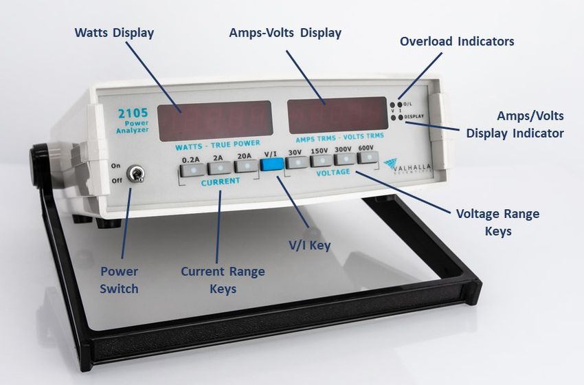
Table of Contents
Chapter 1 General Information ................................................................................................................ 6
 Introduction ............................................................................................................................................ 6

 Manual Description ................................................................................................................................. 6

 Instrument Identification ........................................................................................................................ 6

Chapter 2 Unpacking and Installing .......................................................................................................... 7
 Introduction ............................................................................................................................................ 7

 Inspection ................................................................................................................................................ 7

 Line Voltage/Fuse Selection .................................................................................................................... 7

 Bench Use ................................................................................................................................................ 7

 Rack Mounting ........................................................................................................................................ 7

 Safety Precautions ................................................................................................................................... 8

Chapter 3 Specifications ........................................................................................................................... 9
 Range and Resolution Table .................................................................................................................... 9

 Accuracies ............................................................................................................................................... 9

 Operating Specifications ....................................................................................................................... 10

 Environmental and Physical Specifications ........................................................................................... 10

Chapter 4 Optional Accessories .............................................................................................................. 11
 Optional Accessories ............................................................................................................................. 11

Chapter 5 Operations ............................................................................................................................. 12
 General .................................................................................................................................................. 12

 Front Panel Controls .............................................................................................................................. 12

 .......................................................................................................................................................... 12

 Power Switch .................................................................................................................................... 12

 V/I Key and Amps/Volts Display Indicator ........................................................................................ 12

 Current Range Keys ........................................................................................................................... 12

 Voltage Range Keys ........................................................................................................................... 13

 Peak Amp Overload Indicator ........................................................................................................... 13

 Peak Volt Overload Indicator ............................................................................................................ 13

 3
Amps-Volts Display ........................................................................................................................... 13

 Watts – True Power Display .............................................................................................................. 13

 Rear Panel Controls ............................................................................................................................... 14

 Making Connections .............................................................................................................................. 14

 Using the X-21 ................................................................................................................................... 15

 Using CTs and PTs ............................................................................................................................. 15

 Current Transformers ....................................................................................................................... 15

 Potential Transformers ..................................................................................................................... 16

 Using Both CTs and PTs ..................................................................................................................... 17

 Manipulating the Data .......................................................................................................................... 18

 VA, VAR, PF and ϕ ............................................................................................................................. 18

 PF, Leading or Lagging? ..................................................................................................................... 19

 Accuracies ......................................................................................................................................... 19

Chapter 6 Routine Maintenance ............................................................................................................ 20
 General .................................................................................................................................................. 20

 Periodic Maintenance ........................................................................................................................... 20

 Cleaning ............................................................................................................................................ 20

 Tightening ......................................................................................................................................... 20

 Calibration ............................................................................................................................................. 20

 Equipment Required ......................................................................................................................... 21

 ADC Reference Adjustments ............................................................................................................. 21

 Calibration Connections .................................................................................................................... 22

 Offset Adjustment ............................................................................................................................. 22

 -5 Volt Reference Adjustments ......................................................................................................... 22

 Display Adjustments ......................................................................................................................... 22

 Linearity Adjustments ....................................................................................................................... 23

 20A Range Adjustments .................................................................................................................... 23

 2A Range Adjustments ...................................................................................................................... 23

 0.2A Range Adjustments ................................................................................................................... 23

 4
Watts Zero and Offset Adjustments ................................................................................................. 23

 Full Scale Watts Adjustments............................................................................................................ 23

 AC Adjustments and Checks.............................................................................................................. 24

Chapter 7 Theory of Operations ............................................................................................................. 25
 Functional Descriptions ......................................................................................................................... 25

Chapter 8 Addendums ............................................................................................................................ 27

 5
Chapter 1 General Information
Introduction
This manual has information to perform Inspection, Installation, Measurement Operations, and
Troubleshooting for Valhalla Scientific Model 2105. Also included in this manual are: Specifications, Parts
Lists and Schematics.

Manual Description
This Manual is separated into the 9 following Chapters.

Chapter 1 – General Information Chapter 5 – Operations
Chapter 1 contains a brief description of the Chapter 5 describes all operations including a
instrument and other general information. description of the front and rear panel,
 Measurements and Connections.
Chapter 2 – Unpacking and Installing
Chapter 2 contains information for unpacking Chapter 6 – Routine Maintenance
and inspection the equipment. Also contains Chapter 6 contains maintenance information,
power requirements and installation procedure. such as calibration procedure.

Chapter 3 – Specifications Chapter 7 – Theory of Operation
Chapter 3 contains all specifications, including Chapter 7 describes the theory of operation of all
Ranges, Resolutions, Accuracy, General and circuits and sub circuits used on Valhalla Model
Physical Specifications for Valhalla Model 2105. 2105.

Chapter 4 – Options and Accessories Chapter 8 – Addendums
Chapter 4 contains information on all available Chapter 8 lists updates and addendums for this
options and test leads for the Valhalla Model manual.
2105.

Instrument Identification
Valhalla Scientific instruments are identified by a two-part serial number. The Serial Tag is located
on the rear or bottom of the instrument. The number is in a form of 00-0000. The first two digits,
called the serial number prefix, indicate the model. It changes only when a change is made to the
instrument. The last 3 or 4 digits, called the serial number suffix, are unique for each individual
unit. Be sure to include the entire serial number, both prefix and suffix, in any correspondence
about your instrument.
The serial number can also be found on the Main Board, Calibration Tag and Certificate of
Calibration.

 6
Chapter 2 Unpacking and Installing
Introduction
Valhalla Scientific Model 2105 is accurate, reliable low-cost power measurement devices designed to aid
engineering, production test, and quality assurance departments in determination of product power
consumption from DC and AC power sources. The instruments feature dual independent digital displays.
The left display provides a continuous indication of true power in watts. The right display is switch-
selectable between amperes (true RMS) or volts (true RMS).

Model 2105 provides a fast and convenient method of determining product efficiency, power factor, and
true RMS current draw. Phase angle relationships may be calculated through manipulation of the
displayed quantities.

Inspection
If the shipping carton is damaged, request that the carrier's agent be present when the unit is unpacked.
If the instrument appears damaged, the carrier's agent should authorize repairs before the unit is returned
to the factory. Even if the instrument appears undamaged, it may have suffered internal damage in transit
that may not be evident until the unit is operated or tested to verify conformance with its specifications.
If the unit fails to operate, notify the carrier's agent and the nearest Valhalla Sales Office. Retain the
shipping carton for the carrier's inspection. DO NOT return equipment to Valhalla Scientific or any of its
sales offices prior to obtaining authorization to do so.

Line Voltage/Fuse Selection
The switch on the rear of the 2105 is used to configure the power analyzer for operation at different AC
line voltages. The supply voltages and their corresponding fuses are listed below:

105 to 125 VAC, 50-400Hz = .250 Amp Slo-Blo

210 to 250 VAC, 50-400Hz = .125 Amp Slo-Blo

Note that this switch is for the internal operating voltages required by the power analyzer and should not
be confused with the input voltage selectors on the front of the instrument.

Bench Use
The 2105 is delivered for operation in bench use and special instructions for use in this manner other than
the procedures of optional accessories are not required.

Rack Mounting
An optional kit is available for mounting the 2105 in a standard 19" equipment rack. This is listed in
Optional Accessories section of this manual. Follow the installation diagram included with the kit. If the
2105 is to be transported while mounted in a rack, then it must be supported to prevent upward and
downward movement.

The user should note that the specifications for the 2105 become degraded at high temperatures thus it
is required that sufficient room be allowed for airflow around the 2105. This may be achieved by placing
a minimum 1.75" blank panel above and below the 2105 in the rack.

 7
If a unit placed beneath the 2105 has an unusually hot exterior top surface and it is not possible to alter
its location, it is recommended that an aluminum "reflector" plate be used between this unit and the
2105.

Under no circumstances should the ambient air temperature surrounding the 2105 be allowed to exceed
50°C while in operation or 70°C while in storage.

Safety Precautions
The power connector is a three-contact device and should be mated only with a three-contact connector
where the third contact provides a continuous ground connection. A mating power cord has been
provided. If the power is provided through an extension cable, then the ground connection must be
continuous throughout this cable. Failure to provide a continuous ground connection to the 2105 may
render it unsafe for use!

Lethal voltages are routinely present on the rear terminals of the 2105! Always disable the power
source before changing load or source connections.

 8
Chapter 3 Specifications
This section contains accuracy, operating and environmental specifications for the Model 2105.

Range and Resolution Table
 Table 1

 Current Ranges
 .2000A 2.000A 20.00A
 30.00V 6.000W 60.00W 600.0W
 Voltage
 Ranges
 150.00V 30.00W 300.0W 3000W
 300.0V 60.00W 600.0W 6000W
 600.0V 120.00W 1200.0W 12000W
 Watts

Accuracies
Specified accuracies are valid for a period of 1 year from the date of calibration at 25° C ±5°C,
following a 30-minute warm-up.

Voltage - AC+DC, DC Coupled

DC and 40Hz - 5 kHz: .............................................................................. ±0.1% of reading ±6 digits
5 kHz - 10 kHz: .............................................................................. ±0.5% of reading ±0.5% of range
10 kHz - 20 kHz: .................................................................................. ±1% of reading ±1% of range
(Useable above 20 kHz to 50 kHz with typically an additional 1% error per 10 kHz)

Current - AC+DC, DC Coupled

DC and 40Hz - 5 kHz: ............................................................................. ± 0.1% of reading ±6 digits
5 kHz - 10 kHz: ........................................... ±0.5% of reading ±0.5% of range (12 Amps maximum)
10 kHz - 20 kHz: ................................................. ±1% of reading ±1% of range (2 Amps maximum)
(Useable above 20 kHz to 50 kHz with typically an additional 1% error per 10 kHz)

Watts - True Power (EI A cos φ)

DC and 40Hz - 5 kHz: ............................................................................ ±0.25% of reading ±6 digits
5 kHz - 10 kHz: ........................................... ±0.5% of reading ±0.5% of range (12 Amps maximum)
10 kHz - 20 kHz: ................................................. ±1% of reading ±1% of range (2 Amps maximum)
(Useable above 20 kHz to 50 kHz with typically an additional 1% error per 10 kHz)

 9
Operating Specifications
Crest Factor Response: 50:1 for minimum RMS input, linearly decreasing to 2.5:1 for full scale
 RMS input

Minimum Inputs: 5% of voltage and current ranges for specified accuracies

Maximum Voltage Input: 600VDC or RMS, ±1500VPEAK
(Without damage)

Maximum Current Input: ±35APEAK, 20ADC or RMS continuous; 100ADC or RMS for 16 milliseconds
 without damage

Voltage Input Impedance: 600kΩ

Current Shunt Impedance: 0.01Ω

Max Common Mode: ±1500V peak, neutral to earth

Peak Indicators: Illuminate at 2.5 x full scale for voltage and current

Over-range: 150% of full scale for DC, up to "maximum input" specification

Environmental and Physical Specifications
Temperature Range: 0°C to 50°C operating; -20°C to 70°C storage

Temperature Coefficient: ±0.025% of range per °C from 0°C-20°C and 30°C-50°C

Power Consumption: 105-125VAC or 210-250VAC, 50-400Hz; 25VA maximum

Dimensions: 25cm W x 27cm D x 8cm H (10" W x 10.5" D x 3" H)

Weights: 1.7kg (3.5 lbs) net; 3kg (6 lbs) shipping

Source/Load Connections: 4-terminal heavy-duty input jacks

 10
Chapter 4 Optional Accessories
This section lists the accessories available for the 2105 Digital Power Analyzer. Standard accessories
include a detachable power cord and an operation manual.

Optional Accessories
I-100: Current Transformer
This "clamp-on" type current transformer extends the AC current measurement capability on the 2105 to
100 amps RMS. The 100:1 output ratio is 2% accurate from 45Hz to 1000Hz. The device accommodates
up to 2" diameter conductors.

I-150: Current Transformer
This "clamp-on" type current transformer extends the AC current measurement capability on the 2105 to
150 amps RMS. The 1000:1 output ratio is 2% accurate from 50Hz to 60Hz, and 3% accurate at 60Hz to
10 kHz. The device accommodates up to 2 " diameter conductors.

I-1000: Current Transformer
This "clamp-on" type current transformer extends the AC current measurement capability on the 2105 to
1000 amps RMS. The 1000:1 output ratio is 2% accurate from 50Hz to 1000Hz. The device accommodates
up to 2" diameter conductors.

X21: Load Power Adaptor Cord
This cable is specifically designed for use with the 2105 Power Analyzer. It allows for quick and easy
connection and testing of loads that use a standard AC plug (i.e. televisions, toasters, microwaves, radios,
hair dryers, etc.). The entire cable is 6 feet in length and accommodates supply currents up to 20 amperes.

CC4: Carrying Case
This item is a meter and accessory carrying case designed to protect the Power Analyzer when moved
from one location to another. The case is made of black vinyl and includes a shoulder strap.

R4: Rack Mount Adaptor Kit
This item adapts the Power Analyzer for installation in a standard 19" equipment rack.

 11
Chapter 5 Operations
General
This section of the manual contains complete operating instructions for the Model 2105 Digital Power
Analyzers. Included are control functions, connection methods, and operational precautions.

Front Panel Controls
The functions of all front panel controls and indicators are described in the following paragraphs.

Power Switch
Power is applied to the 2105 by placing the ON/OFF switch in the ON position. Application of power is
indicated by lighting of the digital displays.

V/I Key and Amps/Volts Display Indicator
The Amps/Volts Display Indicator specifies which value is being displayed on the Amps/Volts display. The
user can switch between volts and amps by pressing the V/I key on the front panel keypad.

Current Range Keys
These keys select the range of current that will be measured. For the greatest accuracy, select the range
that provides the highest resolution without exceeding the value of the range.

If the amount of current is unknown, select the highest current range before applying power to the load.
If the amount of current can be approximated, select the appropriate range.

 12
Voltage Range Keys
These keys select the range of voltage that will be measured. For the greatest accuracy, select the range
that provides the highest resolution without exceeding the value of the range.

If the level of voltage is unknown, select the highest voltage range before applying power to the load. If
the level of voltage can be approximated, select the appropriate range.

Peak Amp Overload Indicator
This indicator may be used to alert the user to the presence of spikes on the input signal. If the peak or
steady-state current to the measured load is greater than 250% of the range selected with the Current
Range Key, the "Amps O/L" indicator illuminates. Select a higher current range or reduce the current to
the load to extinguish the indicator. Current and power displays may or may not be correct and should
not be trusted if this indicator is lit.

Peak Volt Overload Indicator
This indicator may be used to alert the user to the presence of spikes on the input signal. If the peak or
steady-state voltage applied to the load is greater than 250% of the range selected with the Voltage Range
Key, the "Volts O/L" indicator will be illuminated. Select a higher voltage range or reduce the supply
voltage to extinguish the LED. Volts and power displays may or may not be correct and should not be
trusted if this indicator is lit.

Amps-Volts Display
When the Volts Display Indicator is ON, the right-hand digital display will show the True RMS

(AC+DC) voltage applied to the rear panel connectors.

When the Amps Display Indicator is ON, the True RMS (AC+DC) current passing through the internal shunt
will be displayed in the right-hand display.

A flashing display in either mode indicates an overload condition. Reduce inputs or increase the ranges
until a stable reading is observed.

Watts – True Power Display
The power dissipated in the load (in watts) is indicated on the left-hand display. This reading is invalid if
either the amps or volts overload indicator is illuminated. These peak indicators occur independently of
whether "Amps" or "Volts" has been selected for the right-hand display. In either case, select a higher
range or reduce the input signals. If the highest range has been selected and a peak O/L indicator is still
on, the measurement may require the use of external dividers and/or current shunts.

 This display includes a polarity (-) sign which indicates the general phase relationship between the voltage
and current. A negative sign indicates that the voltage and current are out of phase. The lack of a negative
sign means that the voltage and current are in phase. Note that a negative sign may also indicate that the
voltage or current leads are reversed. The polarity sign may also be used to determine source or load
power. Load power is that power which is consumed by a load. Source power (-) is that power which is
supplied by a source.
If external dividers or shunts are used, the power display will be a fraction of the actual load power. Simple
ratio calculations will then reveal the power delivered to the load. See Using CTs and PTs on page 16.

 13
Under certain conditions where complex waveforms are being applied to the load, it may be necessary to
select a current and/or voltage range that is well above the true RMS value indicated on the display to
extinguish the "O/L" indicator. This will reduce the resolution of the wattmeter reading but is necessary
for instrument accuracy. The display will blink if the load power is greater than that required for a display
of 19999 (decimal omitted).

Rear Panel Controls
The locations of the rear panel controls are shown in Figure 5-1. The function of the 115V/230V switch
and power cord receptacle were covered on page 8 (Line Voltage/Fuse Selection). It is important to
connect the load in accordance with the L (line) and N (neutral) indications on the rear panel for maximum
safety and accuracy.

 Figure 5-1 | Rear Panel

Making Connections
The 2105 is designed to accommodate a multitude of connection methods allowing the user or test
engineer to design custom harnesses according to the application. The basic guidelines for making
connections are:

 1. The supply voltage is connected between the "L" and "N" terminals (line and neutral).
 2. The current to the load passes through the internal shunt. The load is connected to the right-
 hand

In effect, the Power Analyzer is placed in series with the load to monitor the power drawn by it.

Some connection methods are more complex and require some explaining. These are described in the
following paragraphs.

 CAUTION!

Lethal voltages are routinely connected to the terminals of the 2105. Make sure that power sources are
disabled before making or removing connections.

 14
Using the X-21
Perhaps the easiest and most common method of making connections to the Power Analyzer is using the
Option X21 Load Power Cable. Option X21 allows for quick and easy connection of any device that uses a
standard AC plug. Connections using Option X21 are shown in Figure 5-2.

 Figure 5-2 | 2105 Connections using the X-21

Using CTs and PTs
Current and potential transformers (CTs and PTs) may be used with any Valhalla Digital Power Analyzer to
increase its measurement range. Clamp-on CTs may also be used to simplify power analyzer connections.

Current Transformers
Current transformers (CTs) are used to extend the current measurement capabilities of Valhalla digital
power analyzers. CTs are available in many ratios, maximum current ratings, and isolation voltages.

There are two styles of CTs available, fixed and clamp-on. Fixed CTs are generally used for permanent test
set-ups. The conductor being measured must be disconnected, passed through the center of the CT, and
reconnected. Clamp-on CTs are easier to use because they are just clamped around the conductor. The
conductor need not be disconnected when using a clamp-on CT.

CTs are also used for isolating the power analyzer from high voltage systems. Many high voltage systems
operate at current levels directly measurable by the power analyzer, but with voltages beyond the power
analyzer limits. The isolation voltage rating should be at least 1 ½ times the peak input voltage.

When selecting a CT, try to use decade ratios e.g., 10:1, 100:1, etc. Decade ratios make for easier power
analyzer measurements. The user just mentally moves the current and power display decimal points to
the right the appropriate number of places. Valhalla offers three types of CTs which are listed Optional
Accessories on page 12. Of course, non-decade ratios may also be used. The maximum current rating of
the CT should be selected 1 ½ times the expected current to allow for high crest-factor waveforms.

The ratio accuracy of CTs is usually about 2%. This is quite a bit wider than the accuracy of a digital power
analyzer. The easiest way to improve this accuracy is to measure the actual ratio and use this value when
correcting measurements.

CTs are low frequency devices, typically 50-400Hz. At high frequencies, their phase shift will cause the
power measurement to be in error.

 15
CAUTION!

When using CTs, never open circuit their secondary while power is applied The CT will act
like a step-up transformer and may produce lethal voltages which can damage the operator
and/or the power analyzer.

Figure 5-3 illustrates the basic method of connecting a CT to a digital power analyzer.

 Figure 5-3 | 2105 Connections using a CT

 Figure 5-4 | 215 Connections using a PT

Potential Transformers
Potential transformers (PTs) are used to extend the voltage measurement capabilities of Valhalla digital
power analyzers. PTs are available in many ratios, maximum voltage ratings and isolation voltages.

PTs can be used to isolate the digital power analyzer from high voltage systems. Some high voltage
systems operate at voltage levels directly measurable by the power analyzer but at common-mode

 16
voltages beyond the power analyzer's limits. The isolation voltage rating should be at least 1 ½ times the
common-mode voltage or peak input voltage.

When selecting a PT, try to use decade ratios, e.g., 10:1, 100:1, etc. Decade ratios make for easier power
analyzer measurements. The user just mentally moves the voltage and power display decimal points to
the right the appropriate number of places. Of course, non-decade ratios may also be used. The
maximum voltage rating of the PT should be selected 1 ½ times the expected voltage level to allow for
high crest factor waveforms.

The ratio accuracy of PTs is usually about 2%. This is quite a bit wider than the accuracy of a digital power
analyzer. The easiest way to improve the accuracy is to measure the actual ratio and use this value when
correcting measurements. PTs are low frequency devices, typically 50-400Hz.

At high frequencies, their phase shift will cause the power measurement to be in error. Figure 5-4
illustrates the method of connecting a PT to a digital power analyzer.

Using Both CTs and PTs
Many applications using PTs will use CTs as well. In this case, the power measurement must be multiplied
by both the CT and PT ratios. Figure 5-5 illustrates the method of connecting a CT and PT to a digital
power analyzer.

 Figure 5-5 | 2105 Connections using a PT and a CT

 17
Manipulating the Data
The 2105 directly measures the voltage, current and power used by a single-phase system. Volt-Amperes
(VA), Reactive Volt-Amperes (VAR), power factor (PF), and phase angle (φ) are not displayed but can easily
be calculated from the voltage, current and power measurements. The following paragraphs describe the
methods for calculating VA, VAR, PF, and φ.

VA, VAR, PF and ϕ
The relationships between VA, Watts, VAR, PF and φ can best be described in a graphical manner. Figure
5-6 illustrates these relationships. VA is calculated by multiplying the true RMS voltage and true RMS
current measurements of the digital power analyzer. PF is the cosine of the angle between VA and Watts
and can be calculated using basic trigonometry. VAR is calculated from VA and Watts using Pythagorean's
theorem. Phase angle (φ) may be calculated after the power factor has been determined. The relative
phase (in degrees) between the voltage and current waveforms is the anti-cosine (cos-1) of the power
factor.

 Figure 5-6

 = ∙
 = - ! − !
 = - ! − !
 = - ! − !

 18
PF, Leading or Lagging?
The terms leading and lagging power factor refer to the relative phase shift between the current and
voltage waveforms. The current leads the voltage in a capacitive load while the current lags the voltage
in an inductive load. When calculating power factor using a 2105, there is no way of determining whether
the voltage waveform is leading or lagging the current. An oscilloscope must be used to determine leading
or lagging. Fortunately, most every load has a lagging power factor.

If the load has a transformer, fan, or motor, it is safe to assume lagging power factors and an oscilloscope
is not required.

Accuracies
The accuracies of these calculations are the sums of the accuracies of the voltage, current and power
measurements. For the 2105, the specified accuracies of Chapter 3 should be summed to find the total
uncertainty.

 19
Chapter 6 Routine Maintenance
General
The following paragraphs provide the information required to perform the required periodic maintenance
and basic guidelines for troubleshooting the 2105.

Periodic Maintenance
The 2105 requires little periodic maintenance other than regular performance of the calibration
procedure of Chapter 6. Maintenance which may be required is discussed in the following paragraphs.

Cleaning
It is recommended that the 2105 be operated in a clean environment. However, if the environment is
dusty periodic cleaning of the unit will be necessary.

Loose dirt or dust which has collected on the exterior surfaces of the 2105 may be removed with a soft
cloth or brush. Any remaining dirt may be removed with a soft cloth dampened in a mild soap and water
solution. Do not use abrasive cleaners.

The front panel may be cleaned with a soft cloth and a "Windex" type cleaner. Do not use petroleum-
based cleaners on the front panel.

If required, the 2105 interior may be cleaned by blowing with dry compressed air.

If the 2105 has become heavily soiled with dirt or by other contaminants it is recommended that the unit
be completely overhauled. Contact your local Valhalla Scientific Service Center for details.

Tightening
Tightness of connections to the input terminals is important for safety and reliability of measurements.
Loose connections, especially when working with high current levels, may cause excessive temperatures
to build up on the shunt input terminals. This contact resistance also requires the source to supply
additional power to overcome it.

It is recommended that power be periodically removed, and the integrity of connections checked as they
may have become relaxed.

Calibration
The following procedures should be performed at routine intervals to ensure that the Power Analyzer
remains within specified limits. In addition, calibration should be performed following repairs involving
accuracy determining components.

 20
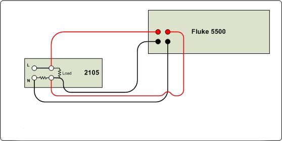
Remove the top cover from the unit to gain access to the internal adjustments. The locations of the
adjustments are listed on the circuit board and on drawing number 2105-600 at the back of this manual.
Apply power to the 2100 and test equipment and allow approximately 30 minutes for stabilization.

Note that the instrument may also be returned to the factory for full calibration traceable to NIST.

Equipment Required
Qty 1 – Multi Calibrator (Fluke 5500A or equivalent)

Qty 1 – Precision Multimeter DMM (Agilent 3458A or equivalent)

ADC Reference Adjustments
 1. Leave the DVM COMMON on the GND POST and connect the DVM POSITIVE lead to TP5.
 2. Adjust RV22 for a 1.0000V on the DVM.
 3. Connect the positive lead to TP6.
 4. Adjust RV23 for a 1.0000V on the DVM.
 5. DVM Negative lead to TP7, DVM Positive lead TP8. Apply +10A
 Adjust RV1 for -100.00mV. (see figure 6-1 for connections to calibrator)
 6. DVM POSITIVE lead to TP1.
 7. Close calibrator lid.

 21
Calibration Connections
Refer to Figure 6-1 if using the Fluke 5500.

 Figure 6-1 | DC Connections

Offset Adjustment
 1. Set the 2105 to Volts and the 150V range. Set the Fluke to 10V operate.
 2. Alternating polarity of the input voltage, adjust RV8 for an equal reading at both polarities.
 3. Adjust RV13 for 10.00

-5 Volt Reference Adjustments
 1. Place the 2105 in the 30V range.
 Apply +30V and adjust RV9 for -5VDC on the DVM.
 2. Select the 150V range.
 Apply +150V and adjust RV10 for -5.0000 VDC on the DVM.
 3. Select the 300V range.
 Apply +300V and adjust RV11 for -5.0000 VDC on the DVM.
 4. Select the 600V range.
 Apply +600V and adjust RV12 for -5.0000 VDC on the DVM.

Display Adjustments
 1. Fluke to 150V operate, 2105 in the 150V range. Adjust RV15 for a 150.00 display.
 2. 2105 in the 600V range, Fluke to 600V operate. Adjust RV16 for a 600.0 display.
 3. Fluke to 300V operate, 2105 in the 300V range. Adjust RV17 for a display reading of 300.0.
 4. Fluke to standby.

 22
Linearity Adjustments
 1. Fluke to 10V operate, 2105 to 150V range. Adjust RV13 for a display reading of 10.00.
 2. Reverse input polarity and adjust RV8 for balanced display.
 3. Repeat until ±10V readings are balanced and reading exactly 10.00.
 4. Fluke to standby.
20A Range Adjustments
 1. 2105 to Amps, 20A range.
 2. Fluke to 10A Operate.
 3. Adjust RV2 for -2.5V DC on the DVM.
 4. Adjust RV14 for a 10A display.
2A Range Adjustments
 1. 2105 to 2A range.
 2. Reversing input polarity repeatedly, adjust RV5 for an equal reading at both polarities.
 3. Adjust RV6 for a display of 1.000 at both polarities.
0.2A Range Adjustments
 1. Fluke to 100mA Operate, 2105 to .2A range.
 2. Reversing input polarity repeatedly, adjust RV4 for an equal reading at both input polarities.
 3. Adjust RV7 for a display of .1000 at both polarities.
 4. Fluke to STBY.
Watts Zero and Offset Adjustments
 1. 2105 to Amps, 2A, 600V ranges.
 2. Adjust RV18 for 000.0 on the watts display.
Full Scale Watts Adjustments
 1. Set the 2105 to the 2A, 600V ranges.
 Apply 1A and 600V, positive polarity.
 Make sure “LO’s” are set to OPEN on the Fluke.
 Adjust RV19 for 600.0 in the watts display.
 2. Fluke to 300V 1A operate, 2105 to the 300V range.
 Adjust RV20 for a watt display of 300.0.
 3. Fluke to 150V 1A operate, 2105 to the 150V range.
 Adjust RV21 for a 150.0 watts display.
 4. Fluke to standby.

 23
AC Adjustments and Checks

 Figure 6-2 | AC Connections

 1. Select AMPS and the 20A, 600V ranges on the 2105.
 2. Set the AC Calibrator for 600V, 10A, 100Hz, 180°, operate.
 3. Adjust RV3 for 10.00 in the current display.
 Check Watts display for 6000 ±6 digits.
 4. Current source to 1A operate.
 Check linearity of AMPS display ±2 digits.
 2105 to the 2A range. Check for 1.000 display ±3 digits.
 5. Reduce current source to 0.1A.
 Check display for .100 ±3 digits.
 2105 to .2A range. Check for .1000 ±8 digits.
 Increase range to 2A and input to 1 amp.
 6. Switch to VOLTS display. Check each voltage range with the corresponding inputs ±6 digits (±20
 digits for the 150V display).
 7. 1A, 120V inputs on the 2A, 150V ranges.
 Check frequency response at 60Hz, 1000Hz and 10 kHz.
 Voltage accuracy ±100 digits at 10 kHz. Current accuracy ±6 digits. Watt accuracy ±6 digits.

 24
Chapter 7 Theory of Operations
Knowledge of circuit operation is a prerequisite for efficient fault finding in the 2105. This section is
divided into two parts. The functional description gives basic descriptions as to the functions of various
circuits in the Power Analyzer. The detailed descriptions explain circuit operation down to component
level.

Functional Descriptions
A block diagram of the Model 2105 is shown in Figure 7-1. Power for the load under test is connected to
one set of rear panel terminals and passes through the instrument to a second set of terminals where the
external load under test is connected. A 0.01Ω current shunt is installed between one input terminal and
one output terminal. The inputs to the voltage amplifier are connected to both power line terminals. The
inputs to the three-stage current amplifier are connected across the current shunt.

The voltage amplifier gain is controlled by the voltage range relays so that it has a full-scale 5-volt output
at the selected range. The gains of the three stages of the current amplifier are 25, 10 and 10, respectively.
The outputs of each current amplifier stage are individually selected by the current range relays for the
0.2, 2 and 20 ampere ranges.

The signal applied to the true RMS converter is determined by the position of the amps/volts selector
relay. The 5-volt full-scale output of the voltage amplifier is the same for the four ranges and the output
of the RMS-DC converter will pass through the scaler when the voltage amplifier output is selected. The
scale factor is controlled by the voltage range relays, which selects the correct voltage to be applied to
the RMS-DC converter. If a current amplifier output is selected, scaling is not required.

The DVM is a true dual slope, integrating digital voltmeter. The full-scale voltage applied to its input is 0.2
volts in the current ranges and 0.3, 1.5, 0.3 and 0.6 volts in the four voltage ranges of the Model 2105.
The voltage measured by the DVM is latched to its internal registers at the end of the measurement cycle.
During the time of the next input measurement, each digit of the previously measured voltage is
sequentially applied to the inputs of the decoder/driver. While the decoded data is present at the output
of the decoder/driver, the display digit selector energizes the appropriate display digit. Thus, the display
is multiplexed from a single BCD output of the DVM and at such a rate that it appears to be continuously
illuminated.

The output of the voltage amplifier and the output of the current amplifier stage are applied to individual
inputs of the power converter. The output of the power converter is passed through a scaler controlled
by the voltage range relays. Again, scaling is necessary since the full-scale output of the voltage amplifier
is the same on all ranges. The DVM which follows the scaler is identical to that used for the amps/volts
display.

 25
Figure 7-1 | 2105 Block Diagram

 WARNING
 HAZARDOUS VOLTAGES MAY BE PRESENT INSIDE THE 2105

Experience has shown that apparent malfunctions are often the result of misinterpretation of the
specifications or operating procedures of the unit. Check to be sure that the cables and other test
equipment are in good order before attempting to repair the 2105.

 26
Chapter 8 Addendums
Immediately following this page may be found any notices regarding manual changes, or operating
considerations for special 2105.

Please refer to any applicable material before attempting to operate your Model 2105.

 27
2105 Wide Range Power Analyzer
 Revision 63-1 (2021)
Copyright © 2021 Valhalla Scientific, Inc. All rights reserved

 28
2105 Wide Range Power Analyzer
 Revision 63-1 (2021)
Copyright © 2021 Valhalla Scientific, Inc. All rights reserved
You can also read