22 May 2019, Coventry Date and City - 2019 Innovation User Conference
←
→
Page content transcription
If your browser does not render page correctly, please read the page content below
2019 Innovation User
    Conference

    22 May 2019, Coventry
    Date and City

1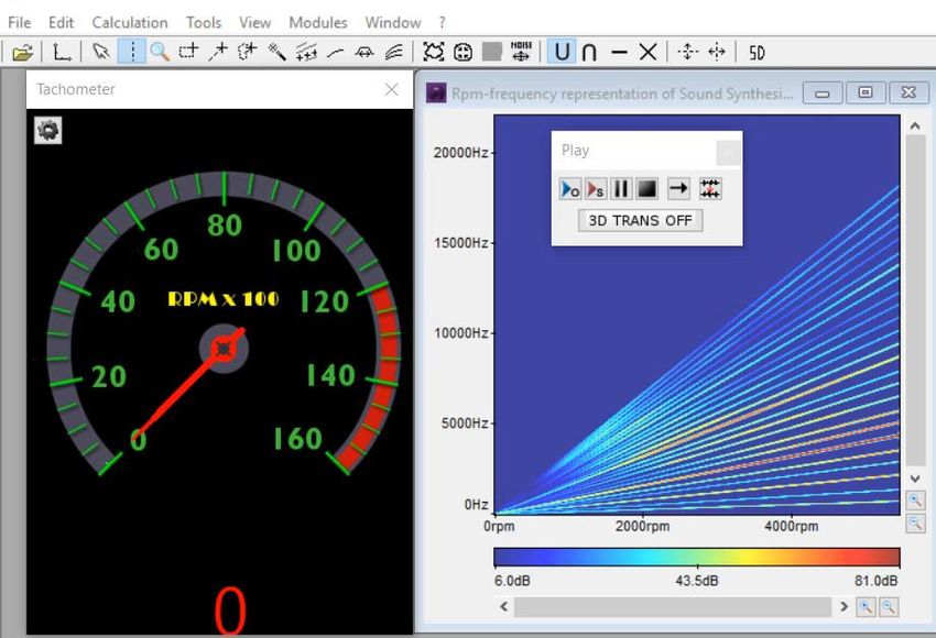
Mechanical Interface Update

    By John Lin
    Lead Engineer
    ANSYS UK

2
New Ribbon Interface
    • To improve usability, Mechanical now organizes its tools and commands using a contextual ribbon. Similar
      commands are organized together in Tabs, making the interface faster to use, more intuitive, and helpful.
    • Additions like the Quick Launch option, expanded Tool Tips and customizable Graphics Toolbar improve
      discoverability as well as usability.

3
File Tab

• The File tab contains a variety of options for managing your project, exporting data, making changes to
  default application settings and setting up how you want your simulation to run.

4
Quick Launch
    • The Quick Launch tool enables you to quickly search for a desired feature or interface option and
      automatically insert or launch the desired item or highlight the pertinent interface option (Take me there).

    • Results display for three categories: Ribbon, Context Tab, and Preferences.

5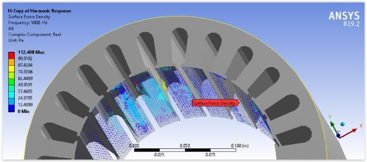
Key Assignments

• Mechanical Hotkeys are now contained in the Key Assignments window.
• Accessible from the Tools group on the Home tab.
• Most keyboard key and key combination shortcuts available in the application can
  now be customized.
• Import and Export options are available.
• In addition, selecting the [Alt] key displays additional keyboard selection options.

6

Manage Interface Layouts

• Users often take the time to position the various interface windows and panes of their simulation in a
  specific manner.
• You can now save your window layout configurations using the Store Layout option of the User
  Defined drop-down menu on the Home tab.
• Stored layouts can be applied to the interface at any point.

7
User Buttons

• Mechanical now enables you to add buttons to the Automation tab that can perform specific actions based
  on Mechanical’s scripting API.
• Using the Manage option of the User Buttons group of the Automation tab, you can create, edit, and
  manage User Defined buttons.
• An icon can be assigned to each button.

8
Selection options

• New options are available in the Graphics window to quick apply the current selection as the scoping for the
  active object
• In addition, when applicable, options also allow you to add to or remove from the current scoping.

9

Engineering Data in Mechanical
 • A new Assignment panel in Mechanical lets you assign a material directly from Engineering Data libraries
   without accessing the Engineering Data Workspace.
 • You can quickly choose a favorite, recent, or project material, or you can search for a material in the active
   libraries. Search by Label, Library, material Model and/or Properties, or use filters.

10
Engineering Data in Mechanical

• When you select a material from the Materials folder in the Outline, you can view the data being used by
  Mechanical and also access edit capabilities in the Engineering Data Workspace.

11
GRANTA Materials Data for Simulation

• The GRANTA Materials Data for Simulation product is now available (in the Mechanical interface only).
• Using the new search capability exposed for Engineering Data in Mechanical, you can quickly search for
  specific materials in this library

12
Commands Object
• The commands object has been updated and now,
     ‐ Provides an auto-completion drop-down menu (based on character entry) as well as a tooltip banner that displays
       the associated command arguments (Mechanical APDL Solver only).
     ‐ Provides a search feature using the Ctrl+F key combination.
     ‐ Includes line numbers.
     ‐ Displays hidden characters such as paragraph marks and spaces.
     ‐ Provides colored syntax highlights for entries such as fixed values, variables, comments, etc. (Mechanical APDL or
       Rigid Body Dynamics solvers only).
     ‐ Provides integrated zoom in and zoom out options. Previously, zooming was performed using the mouse wheel.
     ‐ Has a preference category in the Options dialog that lets you specify the default behavior of some of the above
       features.

13
NASTRAN File Export
• Users can now export your simulation as a NASTRAN bulk data (.nas or .bdf)
• Supported for:
‐ Static Structural
‐ Modal
• Supported through Export Nastran File option in both context menu and context tab for the environment.
Ribbon Tab Context Menu
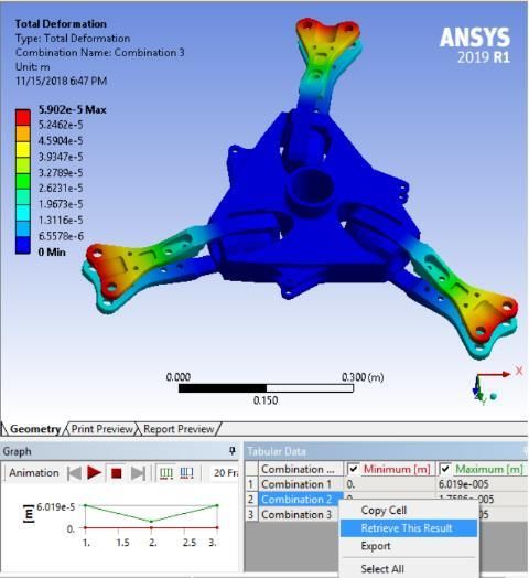
14Mechanical New Solution Combination • With the new solution combination, users can: ● Specify multiple combinations. ● Combine solutions for Static Structural, Transient Structural, and Harmonic Response analyses. ● Specify solution combinations as either Linear or SRSS (Square Root of Summation of Squares). ● Use Tabular Data or a result Set Number to specify which combination you wish to display. ● Import and/or Export the Solution Combination Worksheet as a Comma Separated Value (CSV) file.
Mechanical

Keyframe Animation
 •   Keyframe animation enables you to string together different snapshots of the
     model in the Geometry window to create an animation
     ●  Keyframes are created by positioning the model in the desired orientation
        and clicking on Create Keyframe.
     ●  The application interpolates the transition from keyframe to keyframe to
        create a smooth animation.

                                                               ●   Export the video in various formats:
                                                                   MP4, WMV , AVI and GIF
Mixed-Dimension Analysis
• Mechanical now allows combining two-dimensional (2D) and three-dimensional (3D) bodies in the same
model.
• For shell bodies (only) defined in the X-Y plane, the Dimension property on the Body object lets you set the
body as either 3D (default) or 2D. Mechanical then uses this property to write the appropriate element type
(3D or 2D) to the input file.
Analysis type (Geometry
type) set to 3D in Geometry Dimension set
Workbench to 2D in Mechanical on
Sheet Body
17SMART Crack growth features
• Support multiple Crack Growth using SMART methodology
• Evaluation of SIFS and J-integral results for all cracks in the model
• Newly supported options
‐ Multiple Load Steps
‐ Thermal load
18Topology Optimization - Level-Set
• Density-based method suffer from lack of properly defined boundary Tets & Hex
‐ Forces the designer to interpretation of a poorly defined geometry Manufacturing constraints
• Level-set-based method “pushes” the boundaries • Pull out
• Max Thickness
‐ Result is a water-tight smooth surface, ready for re-analysis, printing or re-CADing
Density-based optimization for various Level Set-based optimization in
commercial products ANSYS Mechanical and Discovery LiveBolt Pretension Solve Behavior option
• Solve Behavior option of “Combined” (default) and “Individual” is exposed. With “Individual” option selected,
the user can create one Bolt Pretension object for multiple Body selection instead of those many objects
With “Individual” option,
only one object is required
20Multilinear Elasticity
The program provides a capability to model multilinear elastic materials. This material causes unloading to occur along
the same path as loading. The multilinear elastic material model is defined with the TB,MELAS command.
Elements support: PLANE182 (plane strain or
axisymmetric), PLANE183 (plane strain or
axisymmetric), SOLID185, SOLID186, SOLID187,
Strain energy SOLSH190, SOLID272, SOLID273, SOLID285,
PIPE288, PIPE289.A New Enhanced Lagrange Multiplier Method (2019R2)
A new Lagrange multiplier (LM) logic is implemented which reduces numbers of
the equation ordering and leads to great performance improvements and better
scalability in DMP run.
Overall Observations for 14 customer’s Models:
Model Detail (DMP 128 CPU cores) Version Solution Time ratio RST File ratio
M1 : Baseline 2019R1 1.00 1.00
M2 : M1 + LM Logic + OUTRES + KEYO,CID,9,1 2019R2 0.70 0.82
M4 = M2 + /FCOMP,RST,SPARSE 2019R2 0.71 0.59
• LM Logic significantly helps reducing solution time
‐ Solution time ratio (relative) reduced by 42%
• /FCOMP,RST,SPARSE significantly reduces RST file size without affecting solution time
‐ RST file ratio reduced by 70%Distributed ANSYS – NOW Default RESULTS FILE COMPRESSION DISTRIBUTED CONTACT DANSYS for SMART FRACTURE
MAPDL - Performance Improvements
                                    DMP Scaling Comparison                                    DMP Scaling Performance                                           DMP Scaling Performance
       25                                                                   10                                                             12
                                                                                                                                                          R19.1
                          2019 R1                                                       2019 R1
                                                                                                                                           10             R19.2
       20                 2019 R2                                               8       2019 R2
                                                                                                                                                          2019 R1
                                                                                                                                                 8        2019 R2

                                                                                                                                       Speedup
                                                                          Speedup
       15                                                                       6
 Speedup

                                                                                                                                                 6
       10                                                                       4
                                                                                                                                                 4

           5                                                                    2
                                                                                                                                                 2

           0                                                                    0                                                                0
               2      4         8      16       32       64   128   256             4   8         16       32         64   128   256                 2     4         8          16        32   64
                                       Number of Cores                                                  Number of Cores                                               Number of Cores

                     Substructuring – New!                                                             SMART                                         Normal Lagrange sliding contact

• New compression algorithm (sparsify) on by default
           –       Smaller results files (10-50% on average)
           –       Lossless compression of results file data
           –       Virtually no performance penalty
           –       Codes that directly read the MAPDL results file without using binlib.dll will no longer work!

24
Output controls and Result file compression
• Additional output controls added which provides granular controls
on the outputs written to the result file. The defaults for these
controls have been chosen carefully based on analysis and physics
type.
❖ Surface Stress
❖ Back Stress
❖ Contact Data
❖ Nonlinear data
❖ Result File Compression
❖ Element Current Density
❖ Electromagnetic Nodal Force
❖ Heat Generation Rate
❖ Result File Compression
• The Result File Compression controls the compression level for the
result file with the following options
• Program Controlled
• Sparse
• Off
25General Axisymmetry 26
GENERAL AXISYMMETRY

General Axisymmetric in WB-Mechanical

• Applicable for 3D Static Structural analysis. General Axisymmetric definition is added under Symmetry folder
  and when scoped to 2D/Surface body makes the behavior of that Body as General Axisymmetric
GENERAL AXISYMMETRY

General Axisymmetric Definition
 1. General Axisymmetric (Solid 272/273) introduces Fourier series into interpolation function to
    describe the change of displacements in the Circumferential (θ) direction.
 2. General Axisymmetric object in mechanical takes Nodal planes input to define number of
    planes and Coordinate system with Axis input to specify the circumferential direction.
 3. The graphics view shows the Axis and Orientation by drawing the line and circle. And it shows
    the number of nodal planes by showing the transformed geometry in different nodal planes

  Solid 272/273               Nodal planes value range from 1 to 12 excluding 2
                               Axis definition must not cut through the body
GENERAL AXISYMMETRY
General Axisymmetric Mesh
1. General Axisymmetric mesh is generated using Generate Mesh/Update action on Mesh folder
2. The base mesh is created on the surface body and then General Axisymmetric mesh is generated on all the
nodal planes as post operation on base mesh.
12 nodal planesGENERAL AXISYMMETRY
Loads and Boundary Conditions
1. Nodal loads are directly applied through the Named selections scoped to Nodes. These loads can
be non-axisymmetric loads as nodes can be picked from any nodal plane
2. Pressure, Remote force, Moment and Displacement load can be applied to the geometric scoping
which can be edge or vertex. If edge of General Axisymmetric body is selected for load
application, then load is applied to all the nodal planes. For Pressure load using Surface effect
option, SURF159 is created to apply the load
Graphics shows the face selected in θ direction where
Load applied to nodes load is applied when Pressure is scoped to edgeGENERAL AXISYMMETRY
General Axisymmetric behavior with Contacts
1. Node to surface contact is created between General Axisymmetric body in contact with other bodies.
CONTA175 is created for the contact side which will be General Axisymmetric body and TARGET170
element is created for 3D target surface
2. Only Bonded contact is supported when Nodal plane 1 is defined
3. Number of nodal plane should be same when General Axisymmetric body is in contact with other General
Axisymmetric body
Nodes in all nodal planes for the General
Axisymmetric scoped edge is considered for contact
Edge to Face contact
between General
Axisymmetric body and
Solid bodyGENERAL AXISYMMETRY
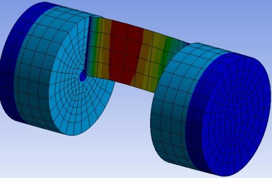
Results
1. All regular results can be extracted on the General Axisymmetric body scoping or Mesh. The results
shown below are Deformation and Stress which are symmetric in the circumferential direction in the
presence of Axisymmetric loading applied in this case
Total deformation scoped to All Stress shown in all nodal planes when
Bodies scoped to an edgeAcoustics & NVH 33
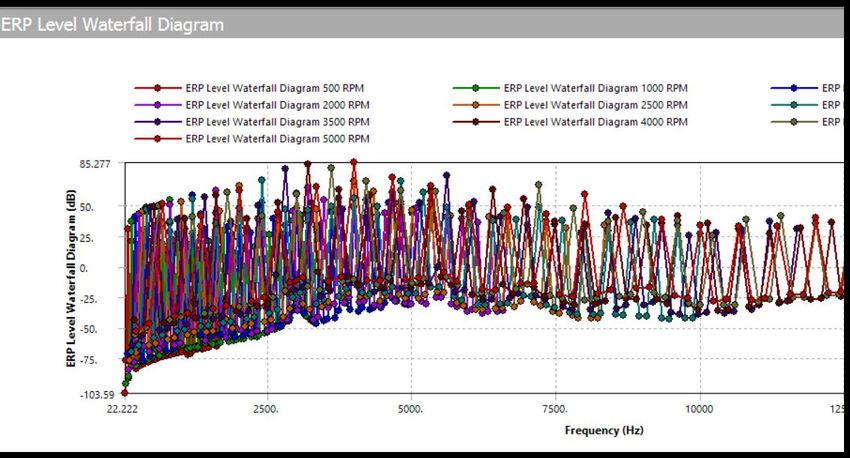
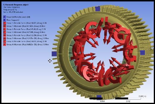
ACOUSTICS

 Maxwell-Mechanical: Multiple RPMs & ERP Waterfall Diagram

• For Electric Machine design, it is important to analyse the acoustic signature of the system. In that goal,
  Equivalent Radiated Power can be calculated for a range of Rotational Velocities and Frequencies. We have
  develop a fully automated workflow to reach this goal.
 ✓ Perform DX Parametric study in Maxwell
 ✓ Transfer EMAG forces to Mechanical for all RPMs
 ✓ Plot ERP Waterfall Diagram
ACOUSTICS

 Maxwell-Mechanical: Multiple RPMs & ERP Waterfall Diagram

• Two mapping strategies available depending on the geometry compliance:
 ✓ Object Based: Integrated Forces / Moments
 ✓ Mesh Based: Surface Force Densities
ACOUSTICS

 Maxwell-Mechanical: Multiple RPMs & ERP Waterfall Diagram

• Equivalent Radiated Power waterfall diagram results provide a global acoustic signature for a range of RPMs
  and frequencies.
ACOUSTICS

Cyclic expansion option for FSI cyclic symmetry

• Cyclic Expansion options for available in Acoustics:
 ✓ Number of sectors to display
 ✓ Starting sector
ACOUSTICS

 Export Results to XML format for VRXP Sound Dimension (Beta)

• Allows XML export for Equivalent Radiated Power and Sound Power Level. XML file can be read in Optis VRXP
  Sound Dimension to synthesize the sound and create a .WAV file.

                            Listen to computed ERP
ACOUSTICS Option to ignore damping in modal Acoustics (Beta) • Available option to ignore acoustic damping material properties (viscosity…) which are defined by default for Air and Water materials. That allows to avoid using Damped solver without deleting those properties in Engineering Data.
ANSYS Cloud

40
ANSYS CLOUD

ANSYS Cloud

              Cloud-based service that provides easy
              access to on-demand HPC directly from
              ANSYS Mechanical & Fluent solver
ANSYS CLOUD
ANSYS Cloud Compute enables “Solve on Cloud”
Preprocessing on desktop –
geometry prep, meshing,
Pre physics, boundary conditions
Files uploaded to cloud for
solve, including automated
Solve optimization and DOE
Validate results with remote
3D viewer. Leave heavy
Check weight results in cloud
Download results to desktop
for detailed post-processing
Post and data managementANSYS CLOUD Accessing ANSYS Cloud • Register for ANSYS Account • Forum to get help and provide feedback • Download ANSYS Cloud Compute ACT App from ANSYS Cloud Portal
Component Mode Synthesis aka Super Element

44
CMS

Outline

• CMS exposure for MSUP harmonic response analysis
• Bushing formulation exposure for Bushing joint which can be internal to Condensed Part
• Support of Acceleration loads in MSUP harmonic using Substructure restart procedure
• Improve disk space and performance by performing file reference for use pass and expansion pass instead of
  file copy
CMS

CMS exposure for MSUP harmonic analysis

• Standalone and Linked MSUP Harmonic analysis can now use CMS based matrix reduction method to work
  with Substructures.

                                                                  Expansion enabled for Condensed Part 2
                                                                  and seen in the deformation results

                   Graphics are made transparent for
                   condensed part and MDOF is
                   displayed on condensed parts
CMS
Bushing formulation for CMS based Modal + Harmonic
• Bushing joint now supports Bushing formulation which can be internal to Condensed Part and can be
included in Generation Pass for Modal and Harmonic analysis
Bushing joint is internal to
condensed part and all other
joints are in the interfaceCMS Acceleration load support for Harmonic analysis • CMS based MSUP Harmonic analysis supports Acceleration load. Since Acceleration is scoped to All Bodies in the analysis, it needs to be applied to both Condensed Part which are within substructures as well as Non- Condensed parts. To support the Acceleration load, substructure restart procedure is performed in Harmonic analysis during use pass.
CMS

Improve disk space and performance

• MODDIR is activated in the Super-element Generation pass of MAPDL solution. This enables the Use pass
  and Expansion pass to do file reference, when required. This avoids file copy of the LN22 files and other files
  shown below to improves disk space and performance due to file copy

                                    cp128.rst
                                    cp128.LN22/LN09/LN20
                                    cp128.full                            These files are read remotely
                                    cp128.cms
                                    cp128.emat
                                                                          through file reference
                                    cp128.bcs

                                    cp128.sub (c)
                                    cp128.bclv (c)                        These files are copied from
                                    cp128.seld/mlv (c)                    condensed part folder during
                                    cp128.db (c)
                                    cp128.esav (c)                        use pass and expansion pass
Distributed ANSYS Enhancements • New features – Support for substructuring expansion passes • Improved scaling – Significantly improved scaling for SMART fracture simulations – Improved scaling for models involving contact elements which use the Normal Lagrange algorithm (KEYOPT(2) = 3) while enabling small sliding behavior (KEYOPT(18) = 1) – Upgraded to Intel MPI 2018 – Faster performance at higher core counts, particularly on Intel Omnipath interconnect
Distributed ANSYS Enhancements

• Substructure expansion passes now supported
                                                                          DMP Scaling Comparison
                                                   25

                                                            2019 R1
                                                   20       2019 R2

                                         Speedup
                                                   15

                                                   10
• 1.7 million DOF; sparse solver
• 3D solid elements
                                                   5
• 12 master DOF
• Linux cluster; each compute node
contains 2 Intel Xeon E5-2695v3                    0
processors, 256GB RAM, SSD, CentOS 7.2                  2      4      8        16        32        64   128   256
• Mellanox FDR Infiniband                                                    Number of Cores
Additive 52
Additive Prep in SpaceClaim

                    Heartcell
                    support

                                              Rod support
                          Block with angled
                          support

53
ANSYS SpaceClaim Additive Prep Work Flow
Create
Define build Optimize Create Export &
Load parts support
envelope orientation supports print
regions
• Import any file format
• Access to all SpaceClaim
features for file
manipulation & repair
• Design parts from scratchAnsys Motion 55
ANSYS Motion
                    ANSYS Motion: A dedicated Multi Body Dynamics tool.

                    ANSYS Motion: A software suite consisting of a baseline
                    package and four toolkits

                        • ANSYS Motion

           ANSYS        •   ANSYS Motion Links Toolkit
                        •   ANSYS Motion Drivetrain Toolkit
           Motion       •   ANSYS Motion Car Toolkit
                        •   ANSYS Motion EasyFlex Toolkit
Ansys Motion – a new paradigm in Multibody Dynamics Ansys Motions’ advanced contact logic and tightly integrated rigid and flexible solvers give a capability that is unique.
Modules Contained Within ANSYS Motion
  Product    Module                                                          Description

             MBD Pro              Multi-Body Dynamics Analysis Package

             FE Dynamics          Multi-Flexible Body Dynamics Analysis Package based on FEM

             Linear               Mode and Natural Frequency Analysis Module

             Fatigue              Fatigue Analysis Module with S/N and E/N curves
                                                                                                                        The ANSYS Motion package
  ANSYS                                                                                                                 contains all of the these
             Modal                Modal Flexible Body Module
  Motion
                                                                                                                        modules as standard
             SMP                  Parallel Processing Module for Solver

             MATLAB Interface     Co-simulation with MATLAB Simulink

             FMI                  Co-simulation based on FMI

             API DEV. Execution   API module for developers

             CAR Toolkit          Vehicle Dynamics Analysis Toolkit

             LINKS Toolkit        Tracked Vehicle Dynamics Analysis Toolkit, Belt and Chain Dynamics Analysis Toolkit
                                                                                                                        Toolkits can be used to aid
  Toolkits
             DRIVETRAIN Toolkit   Power Transfer System Dynamics Analysis Toolkit for NVH                               preprocessing for specialist
                                                                                                                        applications
             EASYFLEX Toolkit     Multi-Flexible Body Dynamics Analysis Package based on MeshFree technology
ANSYS Motion distinctions
• User wants to get more accurate boundary conditions for static analyses through analysis of complete system dynamics.
• ANSYS Motion has the most advanced solver of any commercially available multi-body dynamics tool.
• ANSYS Motion is strong when it comes to contact of complex geometry and high speed rotating problems.
• ANSYS Motion can solve large deformation problems in the time domain while also considering non-linear material properties
Timing Chain Brake Ball Screw Foam
Rigid-to-Rigid Contact Flex-to-Flex Contact Rigid-to-Flex Contact Rigid-to-Flex Contact
ADAMS 3,000 min RecurDyn 4.7 days RecurDyn Not Solved RecurDyn 780 min.
Ansys Ansys Ansys Ansys
46 min. 6 min. 40 min. 45 min.
Motion Motion Motion MotionThank You and Questions 60
You can also read