A Modular Experimentation Methodology for 5G Deployments: The 5GENESIS Approach
←
→
Page content transcription
If your browser does not render page correctly, please read the page content below
sensors
Article
A Modular Experimentation Methodology for 5G
Deployments: The 5GENESIS Approach
Almudena Díaz Zayas 1, * , Giuseppe Caso 2 , Özgü Alay 2,3 , Pedro Merino 1 ,
Anna Brunstrom 4 , Dimitris Tsolkas 5 and Harilaos Koumaras 6
 1    ITIS Software, Universidad de Málaga, Andalucía Tech, 29071 Málaga, Spain; pmerino@uma.es
 2    Simula Metropolitan Center for Digital Engineering, Pilestredet 52, 0167 Oslo, Norway;
      giuseppe@simula.no (G.C.); ozgu@simula.no (Ö.A.)
 3    Deparment of Informatics, University of Oslo, 0315 Oslo, Norway
 4    Deparment of Mathematics and Computer Science, Karlstad University, 651 88 Karlstad, Sweden;
      anna.brunstrom@kau.se
 5    Fogus Innovations & Services, 161 21 Kesariani, Greece; dtsolkas@fogus.gr
 6    NCSR Demokritos, Institute of Informatics and Telecommunications, 153 41 Paraskevi, Greece;
      koumaras@iit.demokritos.gr
 *    Correspondence: adz@uma.es

 Received: 3 October 2020; Accepted: 17 November 2020 ; Published: 20 November 2020

 Abstract: The high heterogeneity of 5G use cases requires the extension of the traditional
 per-component testing procedures provided by certification organizations, in order to devise and
 incorporate methodologies that cover the testing requirements from vertical applications and services.
 In this paper, we introduce an experimentation methodology that is defined in the context of the
 5GENESIS project, which aims at enabling both the testing of network components and validation of
 E2E KPIs. The most important contributions of this methodology are its modularity and flexibility,
 as well as the open-source software that was developed for its application, which enable lightweight
 adoption of the methodology in any 5G testbed. We also demonstrate how the methodology can be
 used, by executing and analyzing different experiments in a 5G Non-Standalone (NSA) deployment at
 the University of Malaga. The key findings of the paper are an initial 5G performance assessment and
 KPI analysis and the detection of under-performance issues at the application level. Those findings
 highlight the need for reliable testing and validation procedures towards a fair benchmarking of
 generic 5G services and applications.

 Keywords: 5G; testbeds; experimentation; methodology

1. Introduction
     The 5th Generation of mobile networks (5G) enables innovative use cases and services that
provide the over the top service providers (a.k.a, verticals) with unprecedented performance
capabilities. Indeed, it is expected that the 5G performance will span over the three extremes of
bandwidth, latency, and capacity requirements, which enable enhanced Mobile Broadband (eMBB),
Ultra Reliable and Low Latency Communication (URLLC), and massive Machine Type Communication
(mMTC), respectively [1]. This potential is supported by a variety of technologies, including the
Software-Defined Networking (SDN), the Network Function Virtualization (NFV), the Network Slicing,
and the Multi-access Edge Computing (MEC). However, the quantification of 5G performance in
an end-to-end (E2E) level is still ongoing, since the high heterogeneity of the enabled use cases requires
various Key Performance Indicators (KPIs) and different target values [2,3]. Irrefutable, vertical- and
use case-oriented 5G testing methodologies, and experimentation processes are required, which have

Sensors 2020, 20, 6652; doi:10.3390/s20226652                                 www.mdpi.com/journal/sensors
Sensors 2020, 20, 6652 2 of 25
to incorporate E2E aspects, far beyond the conventional component-oriented testing (which, so far,
is mainly focused the radio access network [4]).
In this context, huge efforts are being made worldwide by 5G standardization, research,
and stakeholder communities towards the implementation of experimental testbeds, where 5G
technologies and KPIs can be reliably measured and validated in heterogeneous scenarios.
Such testbeds should be flexible and automatically reconfigurable, employ different technologies
(from early stage standardization to commercial components), and be able to reproduce several
network conditions. This would enable common procedures for a fully automated experimentation,
following a Testing as a Service (TaaS) paradigm [3]. To this end, EU and US programs,
such as 5G Public Private Partnership (5G-PPP) (https://5g-ppp.eu (accessed on 30 August 2020).)
and Platforms for Advanced Wireless Research (PAWR) (https://advancedwireless.org (accessed on
30 August 2020).), are specifically focusing on the realization of 5G testing platforms, aiming at
providing trustworthy environments, where eMBB, URLLC, and mMTC verticals can quantify the
expected performance of their services and the corresponding KPIs.
As part of the 5G-PPP initiative, the EU-funded 5GENESIS project (https://5genesis.eu
(accessed on 30 August 2020)) is realizing a 5G facility composed of five different testbeds in Europe,
accessible for both per-component and E2E experimentation purposes [5]. A reference architecture for
common and lightweight access to the 5GENESIS testbeds has been already defined [6], along with an
E2E methodology for testing and validation of 5G technologies and KPIs. More precisely, the 5GENESIS
testing methodology follows a modular approach and it includes three logical components, referring to
three configuration/input information classes required for running an experiment, namely, the test
cases, the scenarios, and the slices. Altogether, they identify an experiment, the definition of which is
also formalized in a global template, referred to as Experiment Descriptor (ED). From the architectural
point of view, the information enclosed in the ED feeds a core functional block of the 5GENESIS
reference architecture, the Experiment Life-cycle Manager (ELCM). ELCM manages the testing
procedure and allows for automatic execution of experiments. Subsequently, a further architectural
block, i.e., the Monitoring and Analytics (M&A) framework [7], is in charge of collecting KPI samples
and complementary measurements during the experiment (Monitoring), and process them for a
statistical validation of the KPI under test (Analytics).
In this paper, we present the 5GENESIS methodology for KPI validation, which aims to cope with
the increased complexity and heterogeneity of testing in the 5G era. The main contributions are:
• we detail the methodology components and corresponding templates, i.e., test cases,
scenarios, slices, and ED. The analysis reveals that the methodology can be used by any 5G
testbed, even outside the 5GENESIS facility, due to its modular and open-source nature [8];
• we analyze the use of the methodology under the 5GENESIS reference architecture, describing all
of the steps leading to a fully automated experiment execution, from the instantiation of needed
resources to the collection and analysis of results;
• we showcase the use of the methodology for testing components and configurations in the 5G
infrastructure at the University of Málaga (UMA), i.e., one of the 5GENESIS testbeds; and,
• by means of our tests in a real 5G deployment, we provide initial 5G performance assessment
and empirical KPI analysis. The results are provided, together with details on adopted scenarios
and network configurations, making it possible to reproduce the tests in other testbeds (under the
same or different settings) for comparison and benchmarking purposes.
The rest of the article is organized, as follows. Section 2 introduces the background and related
work. Section 3 provides an overview of the 5GENESIS reference architecture, with focus on key
components that are related to the testing methodology. The details of the testing methodology
are described in Section 4. Section 5 describes the realization of the testing methodology in the
UMA testbed, including the set up procedures performed and the definition of the related ED.
The experimentation results are presented in Section 6. Finally, Section 7 provides the final remarks.Sensors 2020, 20, 6652 3 of 25
2. Background and Related Work
In the following, we provide an overview of background and related work, in order to frame
the context and highlight the contribution of this paper. In particular, in Section 2.1, we review the
standardization efforts towards the definition of 5G KPIs and corresponding testing and validation
methodologies and procedures. In Section 2.2, we summarize recent research activity on 5G testing
and field trials, referring to the most relevant 5G experimentation testbeds.
2.1. Standardization on 5G KPI Testing and Validation
Playing a key role in the standardization of mobile communications, the 3rd Generation
Partnership Project (3GPP) also defines the corresponding tests aiming at verifying that mobile
technologies conform to standards. Over the years, 3GPP has defined the testing procedures
for Universal Mobile Telecommunications System (UMTS, i.e., 3G), Long Term Evolution (LTE,
i.e., 4G) and more recently 5G New Radio (NR).
Focusing on the user-end device, i.e., User Equipment (UE), 3GPP TS 38.521-X series details
how a 5G NR UE must be verified at radio level, characterizing both transmit and receive parameters
in terms of maximum transmit power, receiver sensitivity, and spurious emissions, among others.
Conformance to Non-Standalone (NSA) scenarios, which combine NR and LTE cells for the Radio
Access Network (RAN), is covered in [9], while NR-only Standalone (SA) is analyzed in [10,11],
which address sub-6 GHz and mmWave frequency bands, respectively. Performance aspects that are
related to demodulation under different propagation and Signal-to-Noise Ratio (SNR) conditions are
defined in [12]. Additional specifications cover the testing of several 5G NR signaling protocols [13–15],
while [16] focuses on Radio Resource Management (RRM) testing, including the reporting of
power and quality measurements, handover latency, timing accuracy, and other functional metrics.
Another relevant aspect at the UE side is the battery consumption, for which the Global Certification
Forum (GCF) and CTIA-The Wireless Association have proposed a testing methodology in [17],
among others.
Moving at the network side, 3GPP TS 28.552 [18] provides specifications for performance
measurements of Next-Generation Radio Access Network (NG-RAN), 5G Core (5GC), and network
slicing. Moreover, Radio Resource Control (RRC)-related KPIs are measured according to [19,20],
while using the measurement template given in [21].
As regards NFV, the European Telecommunication Standard Institute (ETSI) Group Specification
(GS) NFV-TST [22] covers the testing of functional blocks of the architecture.
The above activities and documents focus on testing of 5G components separately, and they do
not address a fully E2E KPI validation. As analyzed later, our proposed testing methodology allows
for both per-component testing and E2E KPIs validation.
On this latter aspect, an initial recommendation is given in 3GPP TR 37.901 [23], which addresses
the testing of LTE UE at the application layer. In particular, it specifies the procedure to run throughput
tests in a wide set of network scenarios and conditions. When also considering the need for running
similar tests for 5G, 3GPP has recently initiated a study on 5G NR UE throughput performance at the
application layer, which is progressing as TR 37.901-5 [24], as an evolution of TR 37.901. Our work
in 5GENESIS aims at generalizing these recommendations, in order to cover not only throughput,
but also other E2E KPIs from specific verticals, e.g., the Mission Critical Push to Talk (MCPTT) access
time, for which a test case has been already defined and used [25].
Following the E2E approach, 3GPP TS 28.554 [26] uses a network slicing perspective and currently
covers KPIs related to accessibility, integrity, utilization, retainability, mobility, and energy efficiency.
These KPIs are based on internal counters of the network, which are only accessible to the network
operators; in our methodology, in order to provide direct information on the achievable performance
under different 5G use cases, the definitions of KPI privilege instead the end-user perspective, in terms
of Quality of Service (QoS) and Quality of Experience (QoE).Sensors 2020, 20, 6652 4 of 25
TS 28.554 also specifies a template that allows for the categorization of KPIs along with methods,
tools, and calculation steps needed for measuring and validating them. However, it lacks specifications
for the test sequence and the definition of E2E scenarios. We observe that these aspects are key in
order to completely define and take into account the network setup during a test, which includes the
relationships between infrastructure, management and orchestration system, measurement probes,
user traffic, and so on. As a matter of fact, it is hard to contextualize and compare the obtained
results without a proper scenario definition; also, a clear definition of test preconditions is key for
running reproducible tests and obtaining reliable results. For this reason, we have defined our testing
methodology by taking [26] as a reference, and then extrapolating the provided guidelines towards
covering a full list of 5G E2E KPIs. We also aim at a more general and flexible testing approach,
tailored on open experimental testbeds. Hence, we propose a test case template that reuses and
expands the one in [26] in terms of considered fields, while also addressing clear definitions for test
sequence, preconditions, and E2E scenarios.
When considering these aspects, a document by Next Generation Mobile Networks (NGMN) [27]
introduces test case sequence and scenarios, with the latter based on the definitions provided in [28].
The goal is the evaluation of 5G NR performance, and the focus is on 3GPP Release 15 (Rel-15), the first
step of 5G NR standardization, which primarily considers eMBB and some aspects of URLLC use cases.
For both, several KPIs are considered, e.g., latency, user throughput, and mobility, but also capacity,
coverage, energy efficiency, and user experience, among others.
The NGMN approach fuses together, in a monolithic definition of test cases, the testing
procedures (e.g., test sequence), network configurations (e.g., number of exploited network resources),
network conditions (e.g., number of users), and traffic profiles (e.g., used protocol and packet size).
As detailed in the next sections, our testing approach is instead modular, i.e., the logical components
forming an experiment (test cases, scenarios, and slices) are kept separated, ultimately enabling higher
flexibility and adaptability, as well as lightweight extension towards more advanced testing.
Table 1 summarizes the standards and documentation reviewed above.
Table 1. Summary of standards for 5G testing and Key Performance Indicator (KPI) validation.
Main Component Reference Focus
3GPP TS 38.521-3 [9] 5GNR UE RF conformance. NSA
3GPP TS 38.521-1/2 [10,11] 5GNR UE RF conformance. SA FR1/FR2
UE 3GPP TS 38.521-4 [12] 5GNR UE RF conformance. Performance
3GPP TS 38.523-1/2/3 [13–15] 5GNR UE protocol conformance
3GPP TS 38.533 [16] 5GNR UE RRM conformance
GCF/CTIA [17] Battery consumption
RAN/Core 3GPP TS 28.552 [18] RAN, 5GC, and network slicing performance
RAN 3GPP TS 32.425 [19], TS 32.451 [20] RRC aspects
NFV ETSI GS NFV-TST 010 [22] Testing of ETSI NFV blocks
3GPP TR 37.901 [23], TR 37.901-5 [24] 4G/5G throughput testing at application layer
E2E 3GPP TR 28.554 [26] Slicing performance at network side
NGMN [27] eMBB and uRLLC (partial) KPI testing
Network elements 3GPP TS 32.404 [21] Measurement templates
2.2. Research on 5G KPI Testing and Validation
Rigorous testing of 5G E2E solutions is still an emerging research topic, where we find a relevant
gap. There are only a few papers that are devoted to this area.
In the context of the TRIANGLE project, the work in [29] proposes a methodology in order to
automate the control of all the elements in the E2E 5G network path, while [30] focuses on automating
5G apps. Both of the papers aim to test service level KPIs in a 5G E2E lab setup, while the 5GENESIS
methodology described in this paper is tailored for testing and validation in real 5G deployments.
In the context of 5G field trials, several works provide ad-hoc solutions for specific use
cases, scenarios, and KPIs. The authors in [31] study throughput for using 15 GHz band.Sensors 2020, 20, 6652 5 of 25
In [32], the authors test throughput and latency in vehicular communications. The work presented
in [33] analyses throughput, network energy efficiency, and device connection density. The work
in [34] focuses on different methods for generating and evaluating the effect of interference.
Moreover, large scale performance measurements on 5G operational networks and off-the-shelf UEs
have been recently presented in [35,36]. On the one hand, [35] covers a sub-6 GHz NSA deployment in
a dense urban environment, revealing several insights on network coverage, handover mechanisms,
UE energy consumption, and E2E throughput, latency, and application performance. On the
other hand, [36] discusses throughput, latency, and application performance, along with handover
operations, under four different US operators’ networks, with three of them employing NSA
deployment with mmWave 5G cells. The above papers provide valuable preliminary insights on
5G achievable performance; however, technology and KPI validation requires dedicated and fully
controllable testing environments [3], in order to pinpoint specific causes for the observed performance
levels, and ultimately guide towards focused optimized configurations. Our work contributes to these
aspects by providing the definitions of E2E KPIs and of testing procedures for reliable performance
assessment in dedicated environments.
Several testbeds are being developed for supporting reliable experimentation, testing,
and validation of 5G technologies, paradigms, and KPIs, as anticipated in Section 1. Among others,
the 5G Test Network (5GTN) presented in [37] integrates cellular access and core networks with
SDN/NFV, cloud/edge computing, and Internet of Things (IoT) technologies. Targeting more specific
use cases, [38] showcases NFV integration with Unmanned Aerial Vehicles (UAVs), while [39] presents
a SDN-based cloud/edge computing platform for IoT management. IoT experimental testbeds for
mMTC and low-power devices are also presented in [40,41], while an open solution for E2E network
slicing experimentation is given in [42]. Altogether, these testbeds focus on specific 5G/IoT capabilities
and use cases, while 5GENESIS aims at combining several technologies and implementing an E2E
open facility for the experimentation and testing of heterogeneous verticals. Moreover, the above
works do not address the design of procedures for executing properly defined experiments and test
cases, which is instead a key 5GENESIS contribution, as detailed in this paper.
5GENESIS works under the 5G-PPP umbrella with other two EU-funded infrastructure
projects, i.e., 5G-VINNI (https://www.5g-vinni.eu (accessed on 30 August 2020)) and 5G-EVE
(https://www.5g-eve.eu (accessed on 30 August 2020).) Similar goals are also pursued by PAWR
testbeds, i.e., POWDER (https://powderwireless.net (accessed on 30 August 2020).), COSMOS (https:
//cosmos-lab.org (accessed on 30 August 2020)) and AERPAW (https://aerpaw.org (accessed on
30 August 2020)). Altogether, these projects aim at the implementation of distributed 5G facilities in
Europe (5G-PPP) and US (PAWR), where researchers, technology providers, stakeholders, and verticals
can test their solutions in a reliable and reproducible manner. As analyzed later, the testing
methodology that is presented in this paper is currently adopted in the 5GENESIS facility, but it
can be easily reused in other 5G testbeds, also thanks to the open-source nature of the software
components enabling its application [8].
3. Overview of 5GENESIS Approach to KPI Testing and Validation
Before the formalization of the proposed testing methodology, in this section we summarize the
5GENESIS reference architecture and M&A framework, with the latter being a component that is
particularly important when the methodology is applied in 5GENESIS testbeds. The methodology has
been adopted for experimentation in the 5GENESIS UMA testbed, which is fully compliant with the
reference architecture discussed in this section, as detailed in Sections 5 and 6.
3.1. 5GENESIS Reference Architecture
The 5GENESIS approach to the analysis of KPIs for new 5G services developed by vertical
industries relies on the construction of experimental platforms with a common architecture,
as represented in Figure 1.Sensors 2020, 20, 6652 6 of 25
Scenario and UE configuration
Slice and service deployment. Experimenter (Vertical Industry)
UE- Application data
1 7
5GENESIS Portal
Coordination layer Monitoring and Analytics
COORDINATION
(M&A) framework
Automatic experiment
Interfacing Experiment lifecycle manager (ELCM) control
with other
5GENESIS 2 3
platforms Slice Manager
MANAGEMENT &
ORCHESTRATION
NFV Management & Network Management
GUI Application by the Vertical System (NMS)/
Orchestration
Industry or by the final user PNF Management
(MANO)
6
VNFs VNFs Apps 4
EPC /5G 5G NR RAN
INFRASTRUCTURE
Core
Core E-UTRAN
functions
5
CloudRAN
Remote RH
Main Mobile
Global Internet & External Backhaul RATs UEs
data Edge
Applications (including network
center
Vertical Industries-external
part of the service)
Figure 1. 5GENESIS Reference Architecture and Experimentation Flow.
The 5GENESIS architecture is structured in three main layers: Coordination, Management and
Orchestration (MANO), and Infrastructure Layers. It is an abstraction of the 5G network architecture
proposed by 5G-PPP Architecture Working Group in [43], focusing on the experimentation for
demonstrating 5G KPIs. Hence, additional components and interactions have been included to
introduce an experimentation control plane in the architecture. The 5GENESIS architecture includes
the common components for Management and Orchestration (MANO) of services, network slicing,
and infrastructure layer. On top of them, the Coordination Layer has been added in order to introduce
the experimentation control plane and expose testing and automation features towards the verticals.
Thus, the Coordination Layer includes all of the components related to the control of the
experiment execution. Moreover, it also provides the Northbound Interfaces (NBI) towards the
5GENESIS Portal, for sending the description of an experiment and retrieving the results after the
execution. More details are provided in [44]. During the experimentation, the ELCM is responsible for
the sequencing of experiment lifecycle stages, while maintaining the experiment status and providing
feedback on the experiment execution. M&A-related components sitting in the Coordination Layer are
responsible for the complete collection and analysis of the heterogeneous monitoring data that are
produced during the use of the testbed. In particular, in order to collect the monitoring information
from all of the elements of the testbed, the Analytics component retrieves the measurements from
a unified database, in which the various measurement probes ingest, either in real-time or at the end of
each experiment session, the measurements for long-term storage and data post-processing.
In the MANO Layer, the Slice Manager is in charge of the configuration and deployment of the
slices. For doing this, it relies on the Network Function Virtualization Management and Orchestration
(NFV MANO), which is responsible for the orchestration and lifecycle management of Network
Services and Virtual Network Functions (VNFs), and on the Network Management System (NMS),
which is in charge of the management of Physical Network Functions (PNFs).
The Infrastructure Layer implements the E2E 5G network, including UEs, RAN, core network,
main data center, and mobile edge. The main data center and mobile edge refer to the Network
Function Virtualization Infrastructure (NFVI) located at the core and at the edge of the network,
respectively. Section 4 provides more details on how to relate this architecture with the experimentation
methodology and how a sample experiment is run.Sensors 2020, 20, 6652 7 of 25
3.2. 5GENESIS M&A Framework
The KPI validation is managed by the M&A framework [7], which targets the collection of KPIs
and complementary measurements, aiming at reliably validating the former while exploiting the latter
in order to verify the infrastructure status during the experiment. Integrated onto the 5GENESIS
architecture, the M&A framework currently includes several Monitoring tools and both statistical and
Machine Learning (ML) Analytics functionalities. It is formed by three functional blocks:
• Infrastructure Monitoring (IM), which collects data on the status of architectural components,
e.g., UE, RAN, core, and transport systems, as well as computing and storage distributed units;
• Performance Monitoring (PM), which executes measurements via dedicated probes for collecting
E2E QoS/QoE indicators, e.g., throughput, latency, and vertical-specific KPIs;
• Storage and Analytics, which enable efficient data storage and perform KPI statistical validation
and ML analyses.
The KPI statistical validation plays a key role in the 5GENESIS methodology. As detailed in
Section 4, 5GENESIS adopts a per-iteration validation approach. Hence, an experiment, as described in
the corresponding ED, consists of executing a given number of measurement iterations. The validation
is first performed on each iteration, and then on the entire experiment. The procedures for calculating
the statistical indicators that validate the KPIs are specified in the test case template, which is part of
the ED along with scenario and slice configurations.
4. Formalization of the Experimentation Methodology
The proposed methodology has been composed in order to specify the actions that are needed
for the execution of an experiment on 5G infrastructures; and, also, to structure the information flow
required from the design and set of an experiment to the collection of the results. When considering the
intense interest from vertical industries to use and assess the benefits of 5G, the proposed methodology
could be used as a basis for any experimentation process in 5G infrastructures and, as such, it moves
beyond its specific application in the infrastructure used in this paper. The open source notion of the
major components that realise the methodology (referring mainly to the Open5GENESIS suite [8])
contributes a lot towards that direction.This section provides the specifications for each of the key
concepts of the 5GENESIS experimentation methodology. More precisely, we focus on the formalization
of the experimentation methodology. i.e., the process of i) specifying templates for the three key entities
that are mentioned above, namely, the test cases, the scenarios, and the slices, and ii) identifying
all of the additional to those templates information needed to run the experiment. The test cases,
the scenarios, and the slices, as well as the complementary information, are needed in order to fully
self-define an experiment.
4.1. Test Case
A test case describes the targeted KPI and the instructions for configuring the network and
performing the measurement(s) to compute it.
Table 2 reports an example of a test case that is devoted to measure the maximum downlink (DL)
throughput at the application level. User Datagram Protocol (UDP) traffic has been used because it is
more appropriate for this assessment, in comparison to Transmission Control Protocol (TCP), where the
measurements could be affected by flow and congestion control mechanisms. Additional test cases
can be found at [25].Sensors 2020, 20, 6652 8 of 25
Table 2. Test case for assessing the maximum throughput available at the application level.
Test Case: TC_THR_UDP Metric: Throughput
Target KPI: UDP Throughput
The UDP Throughput test case aims at assessing the maximum throughput achievable between a source and
a destination.
• Source of packets: Measurement probe acting as traffic generator.
• Destination of packets: Measurement probe acting as recipient.
• Underlying SUT: Network components between the source and destination.
• Measurement conducted at layer: Application. Complementary measurement are collected at lower layers.
Methodology: For measuring UDP Throughput, a packet stream is emitted from a source and received by a data
sink (destination). The amount of data (bits) successfully transmitted per unit of time (seconds), as measured by the
traffic generator, shall be recorded. A UDP-based traffic stream is created between the source and destination while
using the iPerf2 tool. The test case shall include the consecutive execution of several iterations, according to the
following properties:
• Duration of a single iteration: at least three minutes.
• Records throughput over one-second intervals within an iteration.
• Number of iterations (I): at least 25.
iPerf2 configuration:
Parameter iPerf option Suggested value
Throughput measurement interval –interval 1
Number of simultaneously transmitting −4 (in order to generate high data rate in
–parallel
probes/processes/threads the source)
Bandwidth limitation set to above the maximum Depends on the maximum theoretical
–b
bandwidth available throughput available in the network
Format to report iPerf results –format m [Mbps]
Calculation process and output: Once the KPI samples are collected, time-stamped (divided by iteration),
and stored, evaluate relevant statistical indicators, e.g., average, median, standard deviation, percentiles, minimum,
and maximum values, as follows:
• Evaluate the statistical indicators separately for each iteration.
• Evaluate the average of each indicator over the iterations, thus obtaining that same indicator for the test case.
• Evaluate and add a Confidence Interval (CI) * to the obtained indicator, which denotes the precision of the
provided outcome.
* A 95% CI is suggested and it should be evaluated while assuming a Student T-distribution for the data sample,
with I − 1 degrees of freedom. This accounts for non-Gaussian distributions of values collected at each iteration.
Complementary measurements (if available): Throughput at Packet Data Convergence Protocol (PDCP) and
Medium Access Control (MAC) layers, Reference Signal Received Power (RSRP), Reference Signal Received Quality
(RSRQ), Channel Quality Indicator (CQI), Adopted Modulation, Rank Indicator (RI), Number of MIMO layers, MAC,
and Radio Link Control (RLC) Downlink Block Error Rate (BLER).
For each measurement (or selected ones), provide the average per iteration and for the entire test case, following the
procedure in “Calculation process and output”.
Note: packet loss rate is not recorded because constant traffic in excess of the available capacity will be injected and
the excess will be marked as lost packets, as could be expected.
Preconditions: The scenario has been configured. In case of network slicing, the slice must be activated. The traffic
generator should support the generation of the traffic pattern defined in “Methodology”. Connect a reachable UE
(end point) in the standard 3GPP interface SGi or N6 (depending on whether the UE is connected to EPC or 5GC,
respectively). Deploy the monitoring probes to collect throughput and complementary measurements. Ensure that,
unless specifically requested in the scenario, no unintended traffic is present in the network.
Applicability: The measurement probes should be capable of injecting traffic into the system as well as determining
the throughput of the transmission.
Test case sequence:
1. Start monitoring probes.
2. Start the traffic generator for transmitting from the client to the server probe, as described in “Methodology”.
3. Record the throughput for each time interval within a trial.
4. Stop the traffic generator.
5. Stop monitoring probes.
6. Calculate and record the KPIs as needed per iteration as defined in “Calculation process and output”.
7. Repeat steps 1 to 6 for each one of the 25 iterations.
8. Compute the KPIs as defined in “Calculation process and output”.
The test case specifies the end points where the measurements are collected, the measurement
tools and corresponding configurations, how to calculate the throughput, the sequence of actions for
executing the test case, and the complementary measurements that can be used for troubleshootingSensors 2020, 20, 6652 9 of 25
and understanding the obtained values. More precisely, the following information is provided in the
test case template:
Target KPI: this field includes the definition of the target KPI. Each test case targets only one
KPI (main KPI). However, secondary measurements from complementary KPIs can also be added
(see “Complementary measurements” field of this template). The definition of the main KPI specifies
the related target metric, the ID of which is declared in the first row of the template. More precisely,
the definition of the main KPI declares at least the reference points from which the measurement(s) are
performed, the underlying system, the reference protocol stack level, and so on. Within the 5GENESIS
experimentation methodology, the term “metric” refers to a generic high-level definition of a target
quality factor (attribute) to be evaluated, i.e., a definition that is independent of the underlying system,
the reference protocol layer, or the tool used for the measurement. The initial set of identified metrics
is specified in [25], based on an abstraction of the set of 5G KPIs defined by 5G-PPP in [45].
Methodology: this field declares the procedure and configurations relevant for defining the
experiment execution, including the acceptable values for the experiment duration, the iterations
required to obtain statistically significant results, and the measurement interval, to mention a few.
Calculation process and output: this field describes the processing performed on the KPI samples
that allows to derive the statistical indicators for the executed test case, ultimately enabling the KPI
validation. As reported in the “Methodology” field, the experiment should be executed for a statistically
significant number of iterations, e.g., I, in order to obtain an accurate picture of the KPI. An example
of calculation process and corresponding output is given in the test case template that is presented in
Table 2.
Complementary measurements: this field defines a list of secondary parameters useful to
interpret the values of the target KPI. On the one hand, getting these measurements is not mandatory
for the test case itself; on the other hand, the M&A framework can exploit them in order to provide more
insights on the experiment execution. As a first step, an overview of the complementary measurements
(e.g., in terms of per-iteration and test case statistical indicators) can be provided to the experimenter
along with the results that are related to the target KPI. Moreover, such measurements can help to
pinpoint anomalous and unexpected behaviors, provide correlation and predictive analyses via ML
tools, and trigger architectural improvements for next experiment executions.
Preconditions: a list of test-specific information about equipment configuration and traffic
description is provided in this field. Additionally, the description of the initial state of the System
Under Test (SUT), required to start executing a test case sequence, is provided.
Applicability: this field reports a list of features and capabilities which are required by the system
in order to guarantee the feasibility of the test.
Test case sequence: this field specifies the sequence of actions to be performed during the
execution of the test case.
Besides the test case reported in Table 2 above, the 5GENESIS Consortium has already defined
several test cases, including the ones for assessing latency KPIs (see Sections 5 and 6). Test cases
covering further 5G KPIs are also available in [25].
4.2. Scenario
The scenario template includes information that is related to network and environment
configurations, and is related to the technologies supported in the experimentation platform. From the
performance perspective, the scenario quantifies the parameters that affect the values of the KPIs to
be measured.
The parameters that are part of the scenario definition are different from those that are specified
for the slice. The scenario parameters establish the working point of the network, including UE location
and mobility conditions, and they provide a guideline for the definition of network conditions, in order
to reproduce realistic situations where to perform the experiments. Hence, the scenario definition
is dependent on the infrastructure. Table 3 provides an example of the description of a 5G NR NSASensors 2020, 20, 6652 10 of 25
scenario. The accessible parameters in each testbed may differ, depending on the type of equipment
available in each of them. Hence, the scenario template aims to be a guideline for the key parameters
that must be known to gain a clear understanding of the results that were obtained during the testing
and identify the context in which the validation is performed.
Table 3. Scenario template applied to a 5G NR NSA deployment with Line of Sight (LoS) between
gNB and UE. The scenario (SC) is denoted SC_LoS_PS, where PS stands for Proactive Scheduling,
a vendor-specific configuration available in the gNB (cf. Section 5.3 for more details).
Scenario ID SC_LoS_PS
Radio Access Technology 5G NR
Standalone/Non-Standalone Non-Standalone
LTE to NR frame shift 3 ms
Cell Power 40 dBm
Band n78
Maximum bandwidth per component carrier 40 MHz
Subcarrier spacing 30 kHz
Number of component carriers 1
Cyclic Prefix Normal
Number of antennas on NodeB 2
MIMO schemes (codeword and number of layers) 1 CW, 2 layers
DL MIMO mode 2 × 2 Close Loop Spatial Multiplexing
Modulation schemes 256-QAM
Duplex Mode TDD
Power per subcarrier 8.94 dBm/30 kHz
TDD uplink/downlink pattern 2/8
Random access mode Contention-based
Scheduler configuration Proactive scheduling
Close to the base station, direct line of
User location and speed
sight, static
Background traffic No
Computational resources available in the virtualized infrastructure N/A
4.3. Slice
Network slicing support is part of the new Service-Based Architecture (SBA) specified by 3GPP in
TS 23.501 [46]. A network slice is defined as “a complete logical network (providing Telecommunication
Services and Network Capabilities) including Access Network (AN) and Core Network (CN)”.
The management and orchestration of network slices is specified in 3GPP TR 28.801 [47]. The list of
Standard Slice Types (SST) specified in [46] includes three slices: eMBB slice, suitable for 5G eMBB
services; URLCC slice, oriented towards 5G URLLC use cases; and, MIoT slice, for massive IoT and
mMTC applications. However, the standard also contemplates the use of non-standard slices.
In the 5GENESIS methodology, the slice specifies the E2E resources specifically allocated in the
network in order to fulfill the performance requirements of the solution under test. A full description
of the slicing mechanisms supported in 5GENESIS can be found in [48] and in the corresponding
GitHub repository [49]. The template that is used to define the specific slice configuration is based on
the Generic Network Slice Template (GST) defined by the Global System for Mobile Communications
Association (GSMA) in [50], and Listing 1 shows a GST example. Hence, a testbed defines different
instances of the slice template, one per supported slice. Subsequently, the slice is configured,
depending on the capabilities of the infrastructure layer, which is, the mapping between the parameters
defined in the template and the values configured in each network component depends on the available
equipment, which can range from commercial base stations to emulators or software-defined solutions.
However, the mapping is transparent to experimenters and vertical use case owners, which just need
to choose among the list of slices offered by the testbed. The selection that is made by the experimenter
is finally used to fill in the slice ID field in the ED.Sensors 2020, 20, 6652 11 of 25
Listing 1. Instantiation of the Generic Network Slice Template. Throughput and Maximum Transfer
Unit (MTU) values are given in kbps and bytes, respectively.
1 {
2 " b a s e _ s l i c e _ d e s c r i p t o r ": {
3 " b a s e _ s l i c e _ d e s _ i d ": " AthonetEPC " ,
4 " coverage ": [" Campus "] ,
5 " de l ay _t o le ra n ce ": true ,
6 " n e t w o r k _ D L _ t h r o u g h p u t ": {
7 " guaranteed ": 100.000
8 },
9 " u e _ D L _ t h r o u g h p u t ": {
10 " guaranteed ": 100.000
11 },
12 " n e t w o r k _ U L _ t h r o u g h p u t ": {
13 " guaranteed ":10.000
14 },
15 " u e _ U L _ t h r o u g h p u t ": {
16 " guaranteed ": 10.000
17 },
18 " mtu ": 1500
19 },
20 }
4.4. Experiment Descriptor
The ED is a data structure that includes all of the values that are required for completely defining
an experiment execution, as shown in Listing 2. It includes the following fields:
Listing 2. ED Template.
1 {
2 Expe riment Type : Standard / Custom / MONROE
3 Automated : < bool >
4 TestCases : < List [ str ] >
5 UEs : < List [ str ] > UEs IDs
6
7 Slices : < List [ str ] >
8 NSs : < List [ Tuple [ str , str ]] > ( NSD Id , Location )
9 Scenarios : < List [ str ] >
10
11 E x c l u s i v e E x e c u t i o n : < bool >
12 R es er v at i on Ti m e : ( Minutes )
13
14 Application :
15 Parameters : < Dict [ str , obj ] >
16
17 Remote : Remote platform Id
18 R e m o t e De s c r i p t o r : < Experiment Descriptor >
19
20 Version :
21 Extra : < Dict [ str , obj ] >
22 }
Experiment type: it is part of the definition of the experiment. The 5GENESIS experimentation
methodology currently supports three types of experiments. However, the methodology is sustainable
and can be easily extended with new types of experiments. The standard experiments are based on the
test cases specified by the 5GENESIS Consortium, and enable the comparison and benchmarking of
different variants of a same solution (devices, services, applications, etc.). The custom experiments
are those that are defined based on specific requirements of the solution under test. For example,
in a custom test case, the measurements could be specific with respect to a product being tested.
Finally, MONROE experiments are containerized experiments initially designed in the MONROE
project [51,52]. Within 5GENESIS, a virtual MONROE node has been developed that decouples the
MONROE software from the MONROE hardware infrastructure. The MONROE virtual node can beSensors 2020, 20, 6652 12 of 25
used at the UE, providing a generalized mechanism for running arbitrary containerized experiments
without any need to update the experimentation framework.
Automated: it indicates if the experiment is fully automated, i.e., no human intervention is
required for the execution. Automated experiments target the execution of exhaustive testing looking
for the benchmarking of the solutions under test. Human intervention is expected when the network
can be configured automatically but the applications and UEs are operated by the vertical use
case owners.
Test Cases: it includes the IDs of the test cases selected to be executed in the experiment.
UEs: it includes the ID(s) of the UE(s) used during the experiment.
Slices: it contains the ID(s) of the slice(s) to be used during the experiment. The full slice definition
is available in a separate data structure, as described in Section 4.3.
NSs: it refers to the Network Services (NSs) that are used during the experiment. Depending on
the target of the experiment, the NSs could be deployed at different stages of the experiment. This stage
is specified in the test case.
Scenarios: the ID(s) of the scenario(s) to be used during the experiment are listed in this field.
The full scenario definition is available in a separate data structure, as described in Section 4.2.
Exclusive Execution: it controls the scheduling of different experiments in the testbed.
An Exclusive experiment is not executed at the same time with other experiments.
Reservation Time: it defines the duration of the experiment when automation is not enabled.
Application: this field depends on the type of experiment and test case. It may be used
for standard and custom experiments to specify the application to run (e.g., in the second case,
the application may be directly defined by the experimenter). In the case of MONROE experiments,
the field defines the container to deploy in the MONROE virtual node.
Parameters: this field depends on the type of experiment. In particular, it is used for specifying
customized parameters in custom experiments, but it could be also used to include tool-specific settings
not explicitly reported in the test case of a standard experiment. For MONROE experiments, the field
provides the configuration for the containers involved in the experiment.
Remote: this field is necessary to support the execution of distributed experiments, possibly
involving two testbeds. It is used to identify the secondary testbed that is part of the experiment.
Remote Descriptor: it contains a secondary ED with the values that are required to configure the
experiment execution in the remote testbed.
Version: it specifies the ED version in use, so that the testbed can customize the handling of the
ED according to any future modification, while keeping compatibility with older EDs.
Extra: this field can be used to add further information. For example, it can be useful for adding
debugging or tracing information, or to support extra functionalities without changing the ED format.
Each testbed needs to create a registry detailing the type of experiments, and the list of supported
test cases, scenarios, slices, NSs, and UEs, since this information is required to fill in the ED. As part
of the implementation open-sourced in [8], 5GENESIS makes available a Web Portal, where this
information can be easily configured and the verticals just need to select between the options available
in the testbed to define an experiment.
4.5. Experiment Execution
The experiment workflow is depicted in Figure 1, on top of the 5GENESIS reference architecture.
In terms of execution flow, labels 1 to 7 represent the steps for describing an experiment (1), to execute
it (2 to 6) and to report results (7). Next, we illustrate the execution of an experiment with an example.
Assume that a service provider would like to assess the delay perceived at the application level
in a certain device. First, the experiment is configured via the Portal. The chosen parameters will
be used in order to fill in the fields of the ED. In the example, the experiment requests the execution
of a Round Trip Time (RTT) test in a static scenario with LoS and good coverage, and the usage of
an URLLC slice. Subsequently, the ED is delivered to the Coordination Layer first and MANO LayerSensors 2020, 20, 6652 13 of 25
then, where the Slice Manager deploys and configures the entire slice indicated by the experimenter
in the ED. In the third step, the scenario is configured via the configurations that are specified in
the corresponding scenario template selected by the experimenter. Among other, in this specific
example, a ping application is installed in the device under test. The scenario can potentially affect the
radio access technology (e.g., the signal strength of the base station), as well as the backhaul and core
networks (e.g., the amount of background traffic in the backhaul). In the fourth step, the ELCM initiates
the ping client, as well as the monitoring probes collecting all of the complementary measurements
specified in the test case (or at least the ones available). The activation of the ping client triggers the
3GPP signaling in order to establish the data connection. In this example, the experiment test case
defines a ping between the UE and the Packet Gateway (P-GW) located at the core network, so we can
skip steps five and six in the execution flow, devoted to the testing of services deployed outside of the
testbed (e.g., at the vertical facility). Finally, M&A post-processes the measurements and reports the
obtained KPI statistical indicators to the experimenter.
The source code for the components described in this section (Portal, ELCM, Slice Manager,
etc) is available under Apache license 2.0 in [8]. The license allows modifying and using the software
without restrictions. The main purpose of this open initiative is to provide a general testing framework
for 5G infrastructures. The framework is flexible enough to cover the testing requirements of 5G
verticals; moreover, it enables the comparability and reproducibility of experiments and results across
5G infrastructures having similar features.
The repository in [8] also includes the probes that were used in Android devices to collect the
radio information, the iPerf and ping agents for Windows PCs and Android devices, and a streaming
agent for video streaming tests. A manual for installing and using all of the components is also
available [44].
5. Experimental Setup
This section and the following one present a practical application of the testing methodology in
the 5G deployment located at the UMA campus, which is described in Section 5.1. The methodology is
applied in order to quantify throughput and latency KPIs in different networks scenarios. We define
the test cases in Section 5.2, while presenting the scenarios and used slice in Sections 5.3 and 5.4,
respectively. Finally, we report the EDs for three experiments executed for our validation purposes in
Section 5.5.
5.1. 5G Deployment at UMA Campus
This section describes the 5G deployment at UMA campus, where the experiments have been
executed. 3GPP TS 37.340 [53] considers different options for the deployment of 5G networks.
The options range from purely 5G solutions, deployed independently from the existing network,
to hybrid solutions, which combine part of the existing infrastructure with 5G NR.
Becasue of the high costs of building native 5G solutions, most operators currently prefer to lean
on and evolve from the existing LTE infrastructure [35,36]. In particular, the combination of 4G and 5G
radio access connected to an LTE EPC is known as NSA operation Option 3x architecture. This option
is also called eUTRA New Radio-Dual Connectivity (EN-DC). Dual Connectivity (DC) was introduced
in 3GPP in order to allow a UE to simultaneously transmit and receive data on multiple component
carriers from/to two cell groups via a master eNB (MeNB) and a secondary eNB (SeNB). In Option 3x,
DC is used in order to allow a device to connect to both 4G and 5G NR.
For this reason, the initial UMA pilot also follows the NSA Option 3x architecture. In Option 3x,
the UE is connected to an eNB that acts as MeNB, and to a gNB that acts as SeNB, as shown in Figure 2.
As said, there is no 5GC in this option and the gNB does not connect to the Mobility Management
Entity (MME) in the EPC. The gNB connects to the eNB to receive requests to activate 5G bearers via
X2 interface. Data bearers can be handled by the MeNB or SeNB, or split between these two. For theSensors 2020, 20, 6652 14 of 25
measurements that are discussed in this paper, the data are handled by the SeNB only (the gNB),
which is the most popular Option 3x variant.
gNB
UE
Internet P-GW S-GW
eNB
MME
EPC
Figure 2. Core and Radio Access Network (RAN) configurations as per 5G NR NSA Option 3x.
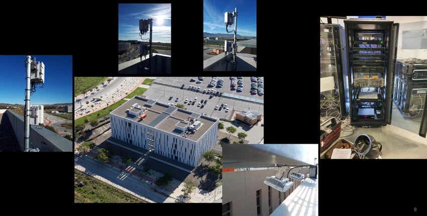
Figure 3 shows the four paired gNBs/eNBs currently deployed in the UMA campus, along with
other infrastructure components, i.e., the server rack hosting the EPC from Athonet, the Baseband
Unit (BBU) from Nokia, and the main data center, in which OpenStack has been adopted as the Virtual
Infrastructure Manager (VIM) and Open Source MANO (OSM) as the solution for NFV management
and orchestration. Moreover, the mobile edge solution provided by Telefonica is based on OpenNebula
and OSM. More details regarding the testbed components can be also found at [54].
Athonet
3 EPC
Nokia 2
Airscale
Micro RRH Main data
N78 (gNodeB) center
1
Main data
center
4 Mobile
edge
Nokia
Airscale BBU Nokia
Micro RRH Airscale BTS
B7 (eNodeB)
Figure 3. 5G NR NSA deployment at UMA campus. The operation band is also reported for the Radio
Remote Heads (RRHs) forming gNBs/eNBs, numbered from (1) to (4).
5.2. Test Case Definition
We have defined two test cases for throughput and latency KPI validation, referred to as
TC_THR_UDP and TC_RTT, respectively.
The details of the TC_THR_UDP test case are provided in Table 2, while TC_RTT is a ping-based
latency test. Similarly to TC_THR_UDP, TC_RTT also specifies 25 iterations; each iteration lasts two
minutes, during which Internet Control Message Protocol (ICMP) ping is performed with ICMP ECHO
REQUEST packets of 56 bytes, sent at a rate of 2 Hz. The ping source is an application running in the
UE and the destination is the P-GW of the core network. The calculation process and output is the
same as defined for TC_THR_UDP in Table 2.Sensors 2020, 20, 6652 15 of 25
5.3. Scenario Definition
Three different scenarios have been defined. Table 3 shows the SC_LoS_PS scenario, which refers
to a LoS situation, where Proactive Scheduling (PS)—a vendor-specific feature in the gNB—is activated.
The other two scenarios, which are denoted SC_LoS and SC_NLoS_PS, are similar to SC_LoS_PS,
but differ in PS deactivation (SC_LoS) or UE location, which is non LoS (NLoS) in SC_NLoS_PS.
(For simplicity, in the following we will also refer to SC_LoS_PS (and SC_LoS) and SC_NLoS_PS as LoS
and NLoS scenarios, respectively, with clear mapping between the two notations.) Next, we discuss,
with more detail, the configurations in Table 3.
After identifying the technology (5G NR) and the deployment mode (NSA), the next scenario
parameter is the LTE to NR frame shift. This setting governs the relative time difference between the
start of the frame timing for both technologies. With a shift of 3 ms, subframe 0 in one technology will
start together with subframe 3 in the other.
Regarding the cell power, the 5G NR cell transmits at 10 W (40 dBm), with an average power
density of 0.25 W/MHz in the full channel, which is located in n78 band, i.e., 3300 to 3800 MHz.
A 5G NR channel of 40 MHz is nominally adopted, with 5G NR numerology 1 and SubCarrier
Spacing (SCS) of 30 kHz. In this case, the maximum number of Physical Resource Blocks (PRB) that
can be used is 106, as per 3GPP TS 38.101-3 ([55] Section 5.3.2). Moreover, the 5G carrier is currently
configured to use two antennas. Hence, we can enable a maximum of two layers to increase the
throughput, taking advantage of the Multiple Input Multiple Output (MIMO) diversity using close
loop spatial multiplexing. We also use a single beam and a maximum modulation of 256-Quadrature
Amplitude Modulation (256-QAM). As per 5G NR Modulation and Coding Scheme (MCS) mapping
in TS 38.214 ([56] Table 5.1.3.1), 256-QAM modulation is enabled with the maximum MCS of 27, 8 bits
encoded per OFDM symbol, and a coding rate of 948/1024. In this setup, the L1 payload spectral
efficiency results of 7.4063 bits per symbol.
The use of Time Division Duplex (TDD) mode, together with 30 kHz SCS, results in a time
resolution of 500 µs for each individual transmission. Within such a time slot, there are 14 OFDM
symbols. Of those, 11 symbols are effectively used for data transmission, as the other three are used
for control information and demodulation of reference signals. At frame level, a 2/8 pattern translates
to DDDDDDDSUU, i.e., a 5 ms pattern of seven DL slots (two patterns per 10 ms frame), one special
slot, and two uplink (UL) slots is used. When considering that our test cases focus on DL throughput,
only the DL slots are effectively used for user data transmission .
With the above setup, the maximum theoretical DL throughput is of approximately 290 Mbps,
derived from multiplying the number of layers (2), PRBs (106), OFDM data symbols (11), and bits per
symbol (8 bits), with the coding rate (0.926), the number of slots in DL used for data transmission (7),
the patterns per frame (2), and the number of frames in one second (100).
As anticipated above, we use PS in SC_LoS_PS and SC_NLoS_PS scenarios, which is a feature
that is available in the gNBs of the UMA deployment. On the one hand, in a generic scheduling
configuration, when a UE needs to transmit data after being inactive for a long interval, it has to
request an UL grant via scheduling requests or even a dedicated connection through Random Access
Channel (RACH). Once the RACH contention is resolved or a scheduling request is successfully
received, the UE will be able to transmit data. This process takes non negligible time and it may not be
optimal for delay-critical use cases. On the other hand, when PS is used, the transmission latency is
minimized, since the gNB pre-assigns resources to the UE, even if the latter has not explicitly requested
them yet. This may clearly bring some overhead, but it could be an optimal solution for scenarios
employing limited amount of mobile devices, where the delay is the critical aspect, e.g., a private
5G network dedicated to time-sensitive communications. Specifically, in our test, we adopt a PS
configuration that allocates UL grants to the UE in every UL suitable opportunity, which, in this
specific configuration, was 10% of the total TDD slots.
Finally, we further comment on the difference between LoS and NLoS scenarios, which clearly
resides on the higher propagation losses in the latter case. In NLoS, the used gNB is not directlyYou can also read