A New Radial Spoiler for Suppressing Vortex-Induced Vibration of a Tubular Tower and Its Practical Design Method
←
→
Page content transcription
If your browser does not render page correctly, please read the page content below

Hindawi
Shock and Vibration
Volume 2021, Article ID 6971178, 10 pages
https://doi.org/10.1155/2021/6971178

Research Article
A New Radial Spoiler for Suppressing Vortex-Induced Vibration of
a Tubular Tower and Its Practical Design Method

 Xing Fu ,1,2 Yao Jiang,1 Wen-Long Du,1 and Bo-Wen Yan 2,3

 1
 State Key Laboratory of Coastal and Offshore Engineering, Dalian University of Technology, Dalian 116023, China
 2
 Key Laboratory of New Technology for Construction of Cities in Mountain Area, Ministry of Education, Chongqing University,
 Chongqing 400045, China
 3
 Chongqing Key Laboratory of Wind Engineering and Wind Energy Utilization, School of Civil Engineering,
 Chongqing University, Chongqing 400045, China

 Correspondence should be addressed to Bo-Wen Yan; bowenyancq@cqu.edu.cn

 Received 28 July 2021; Accepted 31 August 2021; Published 27 September 2021

 Academic Editor: Bing Qu

 Copyright © 2021 Xing Fu et al. This is an open access article distributed under the Creative Commons Attribution License, which
 permits unrestricted use, distribution, and reproduction in any medium, provided the original work is properly cited.
 Circular section tubular members with smaller wind load shape coefficient and higher stability are widely used in ultra-high-
 voltage (UHV) transmission towers. However, the tubular members, especially those with a large slenderness ratio, are prone to
 vortex-induced vibration (VIV) within a specific wind speed range. The sustained vibration of members can easily cause fatigue
 failure of joints and threaten the operational safety of transmission lines. Consequently, a novel countermeasure for the VIV of
 tubular towers using a new type of radial spoiler is proposed, whose mechanism is to change the vortex shedding frequency by
 destroying the large-scale vortexes into small-scale vortexes. Then, the parametric analysis of different variables is carried out
 based on the orthogonal experiment and numerical simulation, including the height H and length B of the spoiler and the distance
 S between adjacent spoilers. The results show that the above three parameters all have significant influences on vortex shedding
 frequency. Additionally, a practical design method of the new radial spoiler is proposed, and the recommended values of H, B, and
 S are 1D∼2D, 1.5H∼3H, and 5D∼12.5D, respectively, where D is the diameter of the tubular member. Finally, a numerical
 verification of the suppression effects is carried out, demonstrating that the proposed quick design method is simple and reliable,
 which can be widely used in the VIV design of tubular towers.

1. Introduction repetitive vibration may cause the looseness of bolts and the
 fatigue failure of welds [6], which will affect the operational
The ultra-high-voltage (UHV) transmission project has the safety of transmission lines. Consequently, for tubular towers,
advantages of long transmission distance, large transmission the prevention and control of the VIV are essential.
capacity, and low power loss [1, 2], which dramatically drives The control methods of the VIV are mainly divided into
technological innovation. Tubular members can increase the two categories: active control and passive control. The
bearing capacity and reduce the weight of tower. Therefore, former applies the external forces on the structure auto-
tubular towers are widely used in UHV transmission lines matically through a real-time monitoring system, while the
[3, 4]. latter adjusts the vortex shedding frequency [7] by altering
 Nevertheless, the wind will produce shedding vortexes on the aerodynamic shape of the structure. The purpose of both
the leeward side of tubular members alternately within a is to interfere with the flow field. Passive control is widely
specific wind speed range [5]. When the shedding frequency used in practice due to its simple principle and treatment
of the vortexes is close to the natural frequency of tubular compared with active control. Zdravkovich [8] divided the
members, the vortex-induced vibration (VIV) occurs, usually passive controls into three categories: (1) surface protrusions
accompanied by larger amplitude vibrations. Long-term (helical strakes, fins, etc.); (2) shrouds (perforated shells,
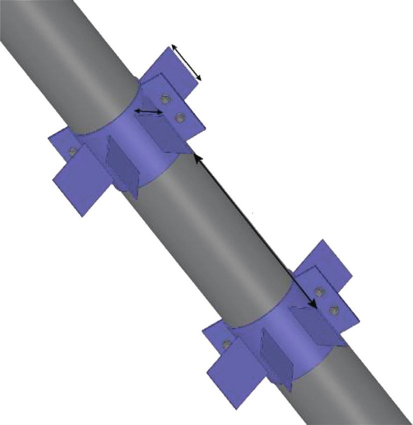
2 Shock and Vibration

axial rods, etc.); (3) near-wake stabilizers (guiding plates, Some related research illustrates that the response of
vanes, etc.), which open the minds for future research. strong transverse direction can be ignored when the VIV
Stansby et al. [9] introduced a spoiler design suitable for the occurs in the members whose joints are connected by the
marine environment, whose effectiveness was verified style shown in Figure 2 [13]. Accordingly, only the response
through a model test. Chen et al. [10] found that, for a of weak transverse direction is considered. The vibration in
flexible riser, a positive VIV suppression effect can be the weak transverse direction can be simplified as a con-
achieved by installing the helical strakes with a reasonable tinuous beam hinged at both� ends; hence, the natural circle
 √����
geometrical configuration. Larsen et al. [11] found that the frequency ωn � π2 /L2 EI/m; i.e., the natural frequency
VIV of bridges can be significantly suppressed by the guide fn � ωn /2π. The wind speed U corresponding to the VIV can
plate, and guide vane arrangements are proved to be equally be obtained from
efficient for other shallow box girders with the correct in- fs D
stallation method. U� , (1)
 Currently, VIV countermeasures are mainly concen- St
trated on ocean and bridge engineering, ignoring electric where fs is vortex shedding frequency and St is the Strouhal
power engineering, especially the tubular transmission number, equaling 0.21 in the subcritical region [14]. When
towers. For tubular towers, stiffening cables are usually used the VIV occurs, fs � fn , U � 6.3 × 0.159/0.2 ≈ 5 m/s.
to suppress the VIV via reducing the deformation and the To accurately simulate the vortex-induced force of wind
slenderness ratio of tubular members; two ends are fixed on field acting on the tubular member, the calculation domain
the main members and the tubular members, respectively. and the mesh are set up accurately, as shown in Figure 3. The
However, this method has not yet been employed widely due calculation domain is set as 28 D × 16 D × L; the distance
to the need for connection plates reserved on the main between the tubular member and inlet, outlet, upper, and
members. Consequently, Jingbo et al. [12] proposed a pa- lower is 8D, 20D, 8D, and 8D, respectively, while the in-
rameter design method of the antivibration hammer to fluence of blocking rate can be ignored [15]. The boundary
suppress the VIV of tubular members, which has a positive conditions are velocity inlet and pressure outlet; the upper,
effect. However, its application is restricted due to the lack of lower, left, and right boundary conditions are symmetrical.
a mature algorithm for the damping of steel strand current. The surface boundary condition of the tubular member is
 Based on previous studies, a new type of radial spoiler is slip wall.
proposed to suppress the VIV of tubular towers. Then, the Previous researches had shown that the spanwise grid
parameters of the spoiler are analyzed, and a design method height needs to be less than 0.0065D to capture more ac-
is given based on numerical simulation and orthogonal curate simulation results for the flow around a three-di-
experiment. Finally, two cases are taken to verify the ap- mensional cylinder [16]. Thus, the spanwise grid height is set
plicability of the design method. as 0.006D in this paper. The selected turbulence model is
 large-eddy simulation (LES) technique, which is more
2. A New Radial Spoiler for the VIV Control precise than the Reynolds-average Navier-Stokes (RANS)
 technique in three-dimensional simulation [17]. PISO al-
2.1. Detailed Description. In this section, a new type of radial gorithm is used to solve the coupling problem of pressure
spoiler (after this referred to as “spoiler” for convenience) and velocity, and the least-squares cell-based method is
based on the passive control method is proposed. A spoiler applied for gradient interpolation. The second-order implicit
comprises two half steel pipes (the steel type is Q345, with scheme is employed for transient scheme, and the second-
the elastic modulus of 206 GPa and the yield strength of order scheme is used for pressure difference and momentum
345 MPa) connected by high-strength bolts. Three same steel difference. The height of the first mesh layer is set as
plates, with a width of H, a length of B, and a thickness of 3.79 × 10− 5 m to satisfy the condition that the nondimen-
3 mm, are welded on each half steel pipe at equal intervals. sional wall distance y+ is less than 1 [18], and the iteration
The distance between the adjacent spoilers is S. Rubber time step is 2 × 10− 4 s.
gaskets are arranged between the tubular members and Figure 4 displays the time history of the lift coefficient
spoilers to increase the contact area and avoid loosening. The Cl , where Cl is defined as Cl � Fl /0.5ρa U2 D, Fl is lift force,
specific design is shown in Figure 1. and ρa is air density. It can be noticed that the lift coef-
 ficient oscillates periodically and the amplitude has ob-
 vious three-dimensional pulsation characteristics, which
2.2. Case Verification and Suppression Mechanism. To reveal is due to the influence of spanwise spatial characteristics of
the suppression mechanism of the proposed method, the flow field. The vortex shedding frequency fs can be ob-
VIV of a tubular member is simulated. A member with a tained from the power spectral density (PSD) curve of the
large slenderness ratio is selected, with an outer diameter D lift coefficient, as shown in Figure 5. At that point,
of 159 mm, an inner diameter d of 151 mm, a length L of fs � fn � 6.3 Hz, which is close to the member’s natural
8320 mm, and a mass m of 15.26 kg/m, which is more prone frequency, and the structural resonance occurs under the
to the VIV. The connection style of the joint is shown in action of VIV.
Figure 2, and the x-axis and y-axis are the strong transverse Table 1 compares the simulation results and the results
direction and weak transverse direction, respectively. obtained from Norberg’s wind tunnel test [19].
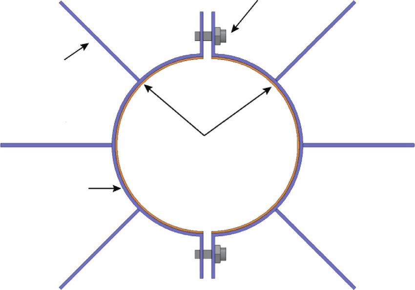
Shock and Vibration 3

 High strength bolt

 B
 H
 Vertical plate

 S
 Rubber gasket

 Half steel pipe

 (a) (b)

 Figure 1: The design scheme of the new spoiler. (a) Basic parameters. (b) Geometric details of the spoilers.

 40

 Ø159×4

 240
 X
 100

 hf=7 Y
 2Ø48

 Figure 2: The connection style of the joint.

 20D

 8D

 8D Left
 Upper

 16D
 Outlet
 Steel pipe
 Right
 Inlet Lower

 L

 Figure 3: The computational domain and mesh generation.

 The Reynolds number of this experiment was about To reveal the suppression mechanism of the spoiler, two
25000. Compared with the data of Norberg’s wind tunnel spoilers are installed on the member for numerical sim-
under this Reynolds number, it is found that the average ulation. The parameters are as follows: H � 100 mm,
drag coefficient Cd , Strouhal number St, and the root mean B � 300 mm, and S � 800 mm. The calculation model is
square of the lift coefficient RMSCl are very close, which shown in Figure 6. The corresponding time history and
indicates the reliability of numerical simulation results. PSD of the lift coefficient are shown in Figures 7 and 8,
Consequently, grid independence verification will not be respectively. It can be seen that the lift coefficient amplitude
carried out in the following research. decreases obviously with the spoilers installed, and fs

4 Shock and Vibration

 1.5 0.2

 1
 0.1
 0.5

 0 0
 Cl

 Cl
 -0.5
 -0.1
 -1

 -1.5 -0.2
 0 2 4 6 8 0 2 4 6 8
 Time (s) Time (s)
 Figure 4: Time history of lift coefficient. Figure 7: Time history of lift coefficient (with spoilers).

 0.3 0.8

 0.25 1.15 Hz
 6.3 Hz 0.6
 0.2
 PSD

 PSD
 0.15 0.4

 0.1
 0.2
 0.05

 0 0
 2 4 6 8 10 0 0.5 1 1.5 2
 Frequency (Hz) Frequency (Hz)
 Figure 5: PSD of lift coefficient. Figure 8: PSD of lift coefficient (with spoilers).

 Table 1: Comparison of experimental and numerical results. and reduce the fluid forces, and this is the primary sup-
 pression mechanism of the spoiler toward the VIV.
Method Cd St RMSCl
Numerical simulation 1.17 0.19 0.47
Norberg’s test 1.19 0.19 0.49
 3. Parametric Analysis
Relative error 1.7% 0.0% 4.1% In Technical Regulations of the Design of Steel Tubular Towers
 of Overhead Transmission Lines (DL/T5254-2010) [20], the
 VIV can be limited by reducing the slenderness ratio to in-
 crease the first-order vibration critical wind speed of tubular
 members, but this method will increase the weight of the tower
 prominently. Therefore, some members are still selected with a
 large slenderness ratio in the practical design. Thus, VIV still
 occurs under certain conditions. Based on a wind tunnel test,
 Jing-Bo et al. [21] pointed out that the VIV can be restrained
 by installing some axially distributed short ribs on the surface
 of steel tubes, or replacing circular cross section steel tubes
 with multi-ribbed steel tubes. However, only conceptual de-
 sign cannot meet practical engineering needs.
 The spoiler for VIV suppression proposed in this paper
 Figure 6: The calculation model with two spoilers. has a good effect with the advantages of easy installation,
 simple processing, and convenient transportation. The
 parametric analysis of H, B, and S of the spoiler is carried out
decreases from 6.3 Hz to 1.15 Hz, which avoids resonance next to provide a design method for the prevention of the
by making the vortex shedding frequency away from the VIV of tubular towers.
member’s natural frequency. The VIV is suppressed, in-
dicating the availability of the spoilers.
 Figure 9 reveals the contour of vortex cores with the 3.1. Orthogonal Experiment. Orthogonal experimental de-
spoilers. The spoilers destroy the large-scale vortexes into sign is a method to study multiple factors and multiple levels
small-scale vortexes, which weaken the intensity of vortexes by selecting some representative points from the
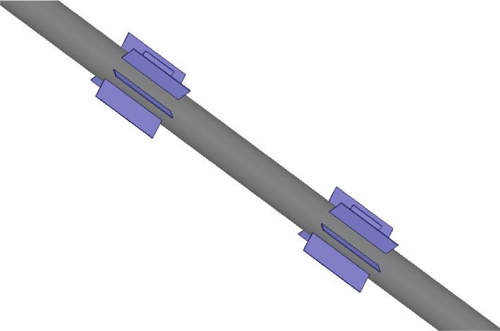
Shock and Vibration 5

 Table 2: Factors and levels.
 Factors
 Level
 a b c
 1 0.2 1 5
 2 0.65 1.5 7.5
 3 1.1 2 10
 4 1.55 2.5 12.5
 5 2 3 15

 PSD of Cl . The results of the 25 cases are set out in Figure 11.
 The value above the blue bar is the vortex frequency fs of
 each case, and the red horizontal line indicates the vortex
 frequency without spoilers; i.e., fs � fn � 6.3 Hz. It can be
 seen that there are apparent suppression effects in every case,
 verifying the effectiveness of the spoilers again. Theoretically,
 the greater the difference between fs and fn , the better the
 suppression effect. For the convenience of designers, the
 vortex frequency fs is linearly converted to the corre-
 Figure 9: Vortex cores (with spoilers). sponding score SC; i.e., SC � 100 − 100fs /fn . The limit fs is
 0 Hz, and SC � 100. Figure 11 is converted to Figure 12 with
 this rule.
comprehensive test according to the orthogonality. Orthog-
onal experimental design can significantly reduce the number
of tests; that is because the selected representative points have 3.2. Result Analysis. In order to further analyze the con-
the characteristics of uniform dispersion. Therefore, this tribution of various factors and levels to the suppression of
method has been widely used in a multitude of fields. vortex shedding, the extremum difference analysis method
 To explore the influence of H, B, and S on the vortex with the advantages of simple calculation and intuitive
shedding frequency, five different levels (No. 1–5) are set for image is applied to analyze the results of the orthogonal
each factor. 125 (53) groups of numerical experiments need experiments, including calculation and judgment. The cal-
to be carried out if the conventional method of control culation includes the extremum difference and experiment
variates is adopted, which will consume an abundance of indexes. The extremum difference can be calculated by
computing resources and time on account of the complexity
 Rj � max Kj1 , Kj2 , Kjm
and high consumption of resources of the 3D simulation
wind field. Therefore, the orthogonal experimental design −min Kj1 , Kj2 , Kjm j � a, b, c m � 1, 2, 3, 4, 5,
and some representative experiments are employed to op-
 (2)
timize the simulation scheme.
 Set H � a D, B � bH, and S � c D with the intention of where Kjm is the sum of the experiment indexes corre-
facilitating the research and expression. Consequently, Ta- sponding to the m level of the factor j, i.e., the sum of SC, and
ble 2 displays the factors a, b, and c with five levels. We Rj is the extremum difference of the factor j.
optimize the experiment scheme via applying a L25 (52 ) The optimal level of the factor j and the optimal level
orthogonal experiment table, and the simulation number is combination of each factor can be judged by the size of Kjm .
reduced from 125 to 25, of which the simulation scheme is Rj reflects the change range of the experiment index when
shown in Table 3. factor j level changes. The larger the Rj is, the greater the
 H, B, and S are rounded upward for the convenience of influence of this factor on the index is, and the more par-
processing in practical engineering. The evaluation index of amount it is. Consequently, the primary and secondary
the suppression effect is measured by the vortex shedding factors can be judged according to the size of Rj . The cal-
frequency fs , and FLUENT is employed to perform 25 culation and judgment of the extremum difference analysis
numerical tests with the same calculation method in Section are directly carried out in Table 4.
1. Case No.12 is designated as an example to demonstrate the For the sake of more intuitively reflecting the influence
simulation process. The levels of the factors a, b, and c are 2, law and trend of each factor and level on fs , the trend chart
2, and 3, respectively, and a � 0.65, b � 1.5, c � 10, i.e., of level and Kjm is drawn with level as abscissa and Kjm as
H � a D � 100 mm, B � bH � 150 mm, and ordinate, as shown in Figure 13.
S � c D � 1600 mm. In order to reduce the amount of
calculation, the height of the calculation domain is set as 6 m, 4. Design Method and Numerical Verification
as shown in Figure 10, and two spoilers are installed for
parametric analysis. 4.1. Practical Design Method. According to the magnitude of
 The lift coefficient Cl is obtained from the simulation extreme difference, the primary and secondary sequence of
results, and the vortex frequency fs can be obtained from the the three factors is a > b > c, i.e., H > B > S. The optimal level
6 Shock and Vibration

 Table 3: Simulation scheme.
 Factors
Case number
 a b c
1 1 1 1
2 2 5 1
3 3 4 1
4 4 3 1
5 5 2 1
6 1 2 2
7 2 1 2
8 3 5 2
9 4 4 2
10 5 3 2
11 1 3 3
12 2 2 3
13 3 1 3
14 4 5 3
15 5 4 3
16 1 4 4
17 2 3 4
18 3 2 4
19 4 1 4
20 5 5 4
21 1 5 5
22 2 4 5
23 3 3 5
24 4 2 5
25 5 1 5

 100
 85 85 88 86 88 88 86 88 86
 80 81 79
 76

 60 53 54
 52
 47
 SC

 40
 29 31
 25 27 27 25 27 25
 20
 6
 0
 1 2 3 4 5 6 7 8 9 10 11 12 13 14 15 16 17 18 19 20 21 22 23 24 25
 Case number

 Figure 12: The values of SC with different case number.

Figure 10: The calculation domain (with spoilers, case No. 12).

 8
 Table 4: Result analysis.
 6.3 (Bare)
 6 5.5 Factors
 Index
 4.4 4.4 4.2
 a b c
 4.3 4.3 4.3 4.4
 fs (Hz)

 4.1
 4 Kj1 161 201 309
 3.1
 2.8 2.8 2.7 Kj2 187 328 354
 2 1.4
 Kj3 285 274 283
 1.1 1.2
 0.9 0.9 0.7 0.8 0.7 0.7 0.9 0.7 0.9 Kj4 433 278 280
 0 Kj5 378 363 216
 1 2 3 4 5 6 7 8 9 10 11 12 13 14 15 16 17 18 19 20 21 22 23 24 25 Rj 272 162 138
 Case number Primary and secondary order 1 2 3
 Figure 11: The values of fs with different case number. Best level combination 4 5 2
Shock and Vibration 7

 Factor a Factor b Factor c
 500 500

 400 400 400

 300 300 300

 Kjm
 Kjm

 Kjm
 200 200 200

 100 100 100

 0 0 0
 1 2 3 4 5 1 2 3 4 5 1 2 3 4 5
 Level Level Level
 (a) (b) (c)

 Figure 13: The level and Kjm trend diagrams of each factor. (a) Factor a. (b) Factor b. (c) Factor c.

combination is the fourth level of factor a, the fifth level of Determine the outer
factor b, and the second level of factor c; i.e., H � 1.55 D, diameter D of the member
B � 3H, S � 7.5 D. Vortex shedding does not need to be
completely suppressed for practical engineering design, only
to keep the vortex shedding frequency away from the
member’s natural frequency. Generally, the 50% suppression Determine H, B of the spoiler
 according to Eq. (3) and Eq. (4)
effect meets the engineering requirements, and the corre-
sponding score SC is greater than or equal to 250 points.
Therefore, the design method of the spoiler is as follows
according to the trend diagram: Determine S of the spoiler
 according to Eq. (5)
 H � 1 D ∼ 2 D, (3)

 B � 1.5H ∼ 3H, (4) Determine the number of spoiler groups m
 according to S and L
 S � 5 D ∼ 12.5 D. (5)

 Based on the previous research, the design process of the Determine the layout of the spoiler
spoiler is sorted out, as proved in Figure 14. Firstly, the outer according to the parity of m
diameter D of the tubular member is determined; then the
height H and width B of the spoiler are determined Figure 14: Design process of the proposed spoiler.
according to equations (3) and (4); then the distance S
between the adjacent spoilers is determined according to the spoilers is selected as H � 1.5 D � 105 mm, rounded up to
equation (5). Additionally, the number m of the spoilers is 110 mm, B � 2 H � 220 mm, S � 12.5D � 875 mm, rounded
determined combined with the length L of the member. up to 900 mm; the layout scheme is demonstrated in
 The parameter m should satisfy the following formula: Figure 15.
mB + (m − 1)S < L, i.e., m < (L + S)/(B + S), and it is In Deng’s wind tunnel test, the wind speed is 3.5 m/s when
rounded down to avoid the spoilers being too close to the the VIV occurs, and the amplitude in the weak transverse
gusset plate. When m is even, one spoiler is set on both sides direction is the largest. The natural frequency in the weak
at the distance S/2 from the center, and then every S is evenly transverse direction is 10.2 Hz. On employing the method in
set on both sides. When m is odd, one spoiler is set in the Section 1, the height of the first mesh layer is 4.82 × 10− 5 m,
center of the member, and then every S is evenly set on both and iteration time step is 2 × 10− 4 s. Figure 16 displays the
sides. comparison of the lift coefficient and its PSD before and after
 the installation of spoilers. The vortex shedding frequency is
 10.28 Hz without the spoilers, which is close to the member’s
4.2. Numerical Verification natural frequency. After the spoilers are installed, the vortex
4.2.1. Example 1. To validate the applicability of the design shedding frequency is reduced to 2.27 Hz, which is away from
method, the tubular members used in Deng’s wind tunnel the member’s natural frequency.
test are selected [22]. The basic parameters are as follows:
D � 70 mm, L � 4598 mm, the slenderness ratio λ � 200, and 4.2.2. Example 2. In addition, the auxiliary member with a
the joint style is the same as Figure 2. According to the small slenderness ratio is selected to verify the effectiveness
design method proposed in the previous section, the size of of the method. The basic parameters are as follows:
8 Shock and Vibration

 Figure 15: The layout of Example 1.

 0.015
 1
 0.01

 0.5 0.005

 0

 Cl
 0
 Cl

 -0.005
 -0.5
 -0.01

 -1 -0.015
 0 2 4 6 8 10 0 2 4 6 8 10
 Time (s) Time (s)
 (a) (b)

 ×10-3
 0.6 1
 10.28 Hz
 0.8 2.27 Hz
 0.4
 0.6
 PSD
 PSD

 0.4
 0.2
 0.2

 0 0
 0 5 10 15 20 0 5 10 15 20
 Frequency (Hz) Frequency (Hz)
 (c) (d)

Figure 16: Comparison of lift coefficient and PSD with and without spoilers for Example 1. (a) Time history of lift coefficient (bare).
(b) Time history of lift coefficient (with spoilers). (c) PSD of the lift coefficient (bare). (d) PSD of the lift coefficient (with spoilers).

 Figure 17: The layout of Example 2.

 0.02
 1

 0.5 0.01

 0
 Cl

 0
 Cl

 -0.5 -0.01

 -1
 -0.02
 0 0.5 1 1.5 2 0 0.5 1 1.5 2
 Time (s) Time (s)
 (a) (b)
 Figure 18: Continued.
Shock and Vibration 9

 ×10-3
 0.3 2.5
 34.2 Hz
 0.25 2
 0.2
 1.5

 PSD
 PSD
 0.15
 1
 0.1
 0.5
 0.05

 0 0
 10 20 30 40 50 0 10 20 30 40
 Frequency (Hz) Frequency (Hz)
 (c) (d)

Figure 18: Comparison of lift coefficient and PSD with and without spoilers for Example 2. (a) Time history of lift coefficient (bare).
(b) Time history of lift coefficient (with spoilers). (c) PSD of the lift coefficient (bare). (d) PSD of the lift coefficient (with spoilers).

D � 70 mm, L � 2354 mm, the slenderness ratio λ � 100, and Data Availability
the joint style is the same as Figure 2. The natural frequency
in the weak transverse direction is 34.19 Hz. The spoiler The data of member dimensions and numerical simulations
scheme is the same as case 1 due to the same diameter, as used to support the findings of this study are included within
shown in Figure 17. the article.
 Figure 18 compares the lift coefficient and its PSD with
and without the spoilers. The vortex shedding frequency is Conflicts of Interest
34.2 Hz without the spoilers, which is close to the natural
frequency of the member, and the VIV occurs, while the The authors declare that they have no conflicts of interest.
dominant frequency of vortex shedding frequency is re-
duced to 10 Hz installing the spoilers, and the VIV is Acknowledgments
suppressed.
 In the above two cases, the suppression effects of VIV are This research was supported by the Opening Fund of Key
all obvious, proving the effectiveness of the quick design Laboratory of New Technology for Construction of Cities in
method, which can be widely used in practical engineering. Mountain Area, Ministry of Education (grant no.
 LNTCCMA-20210112) and the National Natural Science
5. Concluding Remarks Foundation of China (grant no. 52078104).

This study proposed a new type of radial spoiler to suppress References
the VIV of tubular towers. The suppression mechanism of
the spoilers is revealed. Meanwhile, the effectiveness is [1] X. Fu, H.-N. Li, G. Li, Z.-Q. Dong, and M. Zhao, “Failure
verified with the aid of numerical simulation method. Then, analysis of a transmission line considering the joint proba-
the practical design method is given based on the parametric bility distribution of wind speed and rain intensity,” Engi-
analyses of the height H, length B, and distance S conducted neering Structures, vol. 233, Article ID 111913, 2021.
 [2] S. Liang, L. Zou, D. Wang, and H. Cao, “Investigation on wind
by the orthogonal experiment. Finally, the applicability of
 tunnel tests of a full aeroelastic model of electrical trans-
the design method is verified by two examples. The main mission tower-line system,” Engineering Structures, vol. 85,
conclusions can be summarized as follows: pp. 63–72, 2015.
 (1) The new type of spoilers can effectively suppress the [3] L. Tian, J. Liu, C. Chen, L. Guo, M. Wang, and Z. Wang,
 VIV of tubular members, and the suppression “Experimental and numerical analysis of a novel tubular joint
 for transmission tower,” Journal of Constructional Steel Re-
 mechanism is that the spoilers can destroy the vortex
 search, vol. 164, Article ID 105780, 2020.
 structures and reduce the vortex shedding frequency. [4] M. Zhang, G. Zhao, and J. Li, “Nonlinear dynamic analysis of
 (2) The recommended values of H, B, and S are 1D∼2D, high-voltage Overhead transmission lines,” Shock and Vi-
 1.5H∼3H, and 5D∼12.5D, respectively. The design bration, vol. 2018, pp. 1–35, 2018.
 scheme of the spoiler can be obtained through the [5] F. Wang, K. Du, J. Sun, F. Huang, and Z. Xiong, “Shaking table
 outer diameter D of the member quickly. Array tests of an ultra-high-voltage cup-type transmission
 tower-line system,” Shock and Vibration, vol. 2019, pp. 1–20,
 (3) The applicability of the design method is verified 2019.
 through two examples, and the results show that the [6] X. Fu, H.-N. Li, G. Li, and Z.-Q. Dong, “Fragility analysis of a
 design method is simple and reliable, which provides transmission tower under combined wind and rain loads,”
 a new idea for the prevention and control of VIV in Journal of Wind Engineering and Industrial Aerodynamics,
 tubular towers. vol. 199, Article ID 104098, 2020.
10 Shock and Vibration

 [7] G. S. Baarholm, C. Martin Larsen, and H. Lie, “Reduction of
 VIV using suppression devices—an empirical approach,”
 Marine Structures, vol. 18, no. 7, pp. 489–510, 2005.
 [8] M. M. Zdravkovich, “Review and classification of various
 aerodynamic and hydrodynamic means for suppressing
 vortex shedding,” Journal of Wind Engineering and Industrial
 Aerodynamics, vol. 7, no. 2, pp. 145–189, 1981.
 [9] P. K. Stansby, J. N. Pinchbeck, and T. Henderson, “Spoilers for
 the suppression of vortex-induced oscillations (Technical
 note),” Applied Ocean Research, vol. 8, no. 3, pp. 169–173,
 1986.
[10] D.-Y. Chen, L. K. Abbas, G.-P. Wang, X.-T. Rui, and W.-J. Lu,
 “Suppression of vortex-induced vibrations of a flexible riser
 by adding helical strakes,” Journal of Hydrodynamics, vol. 31,
 no. 3, pp. 622–631, 2019.
[11] A. Larsen, S. Esdahl, J. E. Andersen, and T. Vejrum,
 “Storebælt suspension bridge–vortex shedding excitation and
 mitigation by guide vanes,” Journal of Wind Engineering and
 Industrial Aerodynamics, vol. 88, no. 2, pp. 283–296, 2000.
[12] Y. Jingbo, L. Xilai, D. Songtao et al., “Study on suppression
 method with dampers against vortex-shedding induced wind
 vibration of transmission steel tubular tower members,”
 Building Structure, vol. 46, no. 14, pp. 30–35, 2016.
[13] H. Deng and Z. Zhao, “Numerical simulation of vortex-in-
 duced vibration of steel tubular members in transmission
 tower,” Journal of Tongji University, vol. 45, no. 1, pp. 9–15,
 2017.
[14] C. H. K. Williamson and R. Govardhan, “A brief review of
 recent results in vortex-induced vibrations,” Journal of Wind
 Engineering and Industrial Aerodynamics, vol. 96, no. 6-7,
 pp. 713–735, 2008.
[15] X. Fu, H.-N. Li, and T.-H. Yi, “Research on motion of wind-
 driven rain and rain load acting on transmission tower,”
 Journal of Wind Engineering and Industrial Aerodynamics,
 vol. 139, pp. 27–36, 2015.
[16] P. Parnaudeau, J. Carlier, D. Heitz, and E. Lamballais, “Ex-
 perimental and numerical studies of the flow over a circular
 cylinder at Reynolds number 3900,” Physics of Fluids, vol. 20,
 no. 8, pp. 212–287, 2008.
[17] J. Franke and W. Frank, “Large eddy simulation of the flow
 past a circular cylinder at ReD�3900,” Journal of Wind En-
 gineering and Industrial Aerodynamics, vol. 90, no. 10,
 pp. 1191–1206, 2002.
[18] X. Fu, W.-L. Du, H.-N. Li, G. Li, Z.-Q. Dong, and L.-D. Yang,
 “Stress state and failure path of a tension tower in a trans-
 mission line under multiple loading conditions,” Thin-Walled
 Structures, vol. 157, Article ID 107012, 2020.
[19] C. Norberg, “Flow around a circular cylinder: aspects of
 fluctuating lift,” Journal of Fluids and Structures, vol. 15, no. 3,
 pp. 459–469, 2001.
[20] Technical Regulations of the Design of Steel Tubular Towers of
 Overhead Transmission lines National Energy Administration,
 Beijing, China, 2011.
[21] Y. Jing-Bo, L. Zheng, and W. Jing-Chao, “Prevention of steel
 tube UHV transmission tower aeolian vibration,” Electric
 Power Construction, vol. 29, no. 9, pp. 10–13, 2008.
[22] H. Z. Deng, Q. Jiang, F. Li, and Y. Wu, “Vortex-induced
 vibration tests of circular cylinders connected with typical
 joints in transmission towers,” Journal of Wind Engineering
 and Industrial Aerodynamics, vol. 99, no. 10, pp. 1069–1078,
 2011.
You can also read