60 GHz beam-tilting coplanar slotted SIW antenna array - De ...
←
→
Page content transcription
If your browser does not render page correctly, please read the page content below
Frequenz 2022; 76(1-2): 29–36

Hamsakutty Vettikalladi*, Waleed Tariq Sethi, Mohammed Himdi and Majeed Alkanhal

60 GHz beam-tilting coplanar slotted SIW antenna
array
https://doi.org/10.1515/freq-2021-0069                               researched upon [3]. The use of this band provided ben-
Received March 13, 2021; accepted June 23, 2021;                     efits in terms of wide impedance bandwidths, high gains
published online July 13, 2021                                       and most importantly frequency reuse capabilities mak-
                                                                     ing it suitable for short range communications [4]. For
Abstract: This article presents a 60 GHz coplanar fed
                                                                     long-range communication, mmW was not feasible as it
slotted antenna based on substrate integrated waveguide
                                                                     encountered atmospheric losses beyond 20 GHz due to the
(SIW) technology for beam-tilting applications. The longi-
                                                                     effect of water vapors and oxygen molecules in the air
tudinal passive slots are fed via associated SIW holes adja-
                                                                     while propagation losses were also increased to be 30 dB
cent to the coplanar feed while the main excitation is
                                                                     higher than at 2 GHz when operating in free space [5]. The
provided from the microstrip-to-SIW transition. The antenna
                                                                     losses can be dealt with by using high power transmission
array achieves an impedance bandwidth of 57–64 GHz with
                                                                     signals and high gain antennas.
gains reaching to 12 dBi. The passive SIW slots are excited
                                                                          Various antenna designs have been proposed to
with various orientations of coplanar feeds and associated
                                                                     provide high gain characteristics with minimum losses
holes covering an angular beam-tilting from −56° to +56°
                                                                     at mmW bands [6–9]. One such candidate that stands out
with an offset of 10° at the central frequency. The novelty of
                                                                     is the substrate integrated waveguide (SIW). The SIW
this work is; beam-tilting is achieved without the use of any
                                                                     technology is appreciated because it provides minimum
active/passive phase shifters which improves the design in
                                                                     surface and conduction losses at high frequencies, offers
terms of losses and provide a much simpler alternative
                                                                     low profile, easy integration with planar circuits, low cost
compared to the complex geometries available in the liter-
                                                                     of fabrication and has a well-developed fabrication pro-
ature at the 60 GHz band.
                                                                     cess. The SIW design contains two conducting planes, top
Keyword: array; beam-tilting; coplanar slotted; 60 GHz;              and bottom, that are connected through platted via holes.
SIW antenna.                                                         These vias create a sidewall that makes the waveguide
                                                                     which is built into a printed circuit board (PCB) with the
                                                                     alignment of the vias. Moreover, compared to conven-
1 Introduction                                                       tional transmission lines, SIW has less interference, less
                                                                     radiation loss and excellent isolation [10]. Apart from
Since the inception of wireless communication systems                these advantages, one major drawback associated with
[1], many developments have been proposed and suc-                   the SIW design is in its fabrication procedure. A minute
cessfully deployed especially for the unlicensed milli-              shift in the via placement or sidewall displacement error
meter wave (mmW) band at the 57–64 GHz spectrum                      can cause wave leakages as the wavelength is very small
which is widely known as the 60 GHz radio [2]. More than a           compared to the operating mm‐wave frequencies. Till date
decade ago, the importance of this 60 GHz unlicensed                 many successful SIW designs in the singular and array
band was realized by the scientific research community                form have been presented achieving wide bandwidths
and various systems designs and its applications were                and high gains [11–14]. Another important aspect of the
                                                                     60 GHz short range communication is associated with the
                                                                     beam-tilting capabilities.
*Corresponding author: Hamsakutty Vettikalladi, Department of
Electrical Engineering, King Saud University, Riyadh, 11421, Saudi        As per IEEE 802.11ad, the beam-tilting capabilities is
Arabia, E-mail: hvettikalladi@ksu.edu.sa                             considered an important aspect for 60 GHz short range
Waleed Tariq Sethi, KACST-TIC in Radio Frequency and Photonics       communication. Compared with the single element design,
(RFTONICS), King Saud University, Riyadh 11421, Saudi Arabia         the beam-tilting array antennas provides the advantage of
Mohammed Himdi, Institut d’Electronique et des Technologies du
                                                                     increased gain and better desired direction of the signal
numéRique (IETR), UMR CNRS 6164, Université de Rennes 1, Campus
de Beaulieu, 35042 Rennes Cedex, France
                                                                     with minimum losses and interferences. These beam-tilts
Majeed Alkanhal, Department of Electrical Engineering, King Saud     are achieved via adding phase shifters to the system that
University, Riyadh, 11421, Saudi Arabia                              contracts a drawback to the process in terms of design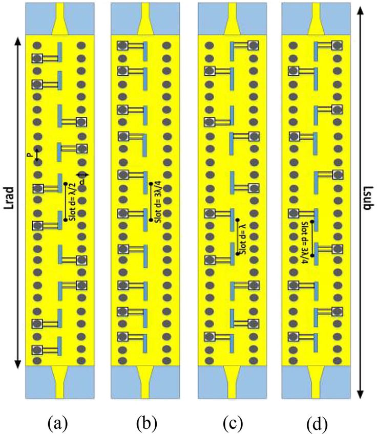
30        H. Vettikalladi et al.: 60 GHz beam tilting antenna

complexity and power loss. Several phase shifters based on      depicted in Figure 1 where the front view with geometric
mechanical, electrical and electronic types have been           symbols are presented in Figure 1(a) while the 3D exploded
reported in the literature for 60 GHz radio [15]. Some known    view in shown in Figure 1(b). The design is fabricated on a
wave distribution networks in the microwave domain have         Lsub × Wsub Rogers RO4003C substrate having permittivity εr
also been used in the mmW band such as the Butler Matrix        of 3.38 and a thickness h of 0.2 mm. The substrate is sand-
[16], the Rotman Lens [17] and MEMS technology [18].            wiched between two conducting copper plates. The bottom
Mechanical phase shifters [19] do provide exact beam-tilts      plate is termed as a full ground while the top plate is termed
but create a problem of physically moving the antenna           as a radiator with length Lrad. Two rectangular slots are
parts which is sometimes not feasible when complex array        etched on the top radiator along the broad wall of the SIW
circuitry is involved. On the other hand, electrical phase      structure with dimensions of Lslot × Wslot. The center-to-
shifters provide fast and efficient beam titling alternate but   center distance between the slots is kept at d = λ/2. The
high array circuitries sometime may increase the overall        formation of the complete SIW structure occurs by the
system cost specially when using MMIC technology [20].          introduction of via holes along the direction of longitudinal
     To alleviate the aforementioned problem, in this work,     slots. The distance between the SIW holes on both sides of
we utilized a cost effective and reliable method to beam-tilt   the longitudinal slots contribute to the working of open-
the radiation pattern of an antenna at the center frequency     ended waveguide structure. The equivalent width (aSIW) of
of 60 GHz. Compared to our previous work [21], the novelty      the SIW holes are calculated as per the cut-off frequency
in this proposed design is the beam-tilting that is achieved    presented in equations (1) and (2) [24].
without the use of any active/passive phase shifters which                                            c
improves the design in terms of losses and provide a much                               W equ =       √̅̅                      (1)
                                                                                                  2f c εr
simpler alternative compared to the complex geometries
available in the literature at the 60 GHz band. The antenna                                             D
                                                                                     aSIW = W equ +                            (2)
design is based on an open-ended waveguide SIW slots                                                  0.95P
that are coupled to coplanar feeds and associated vias. The     These via holes are platted with a conducting material that
beam-tilting principle is applied initially to a two slot SIW   connects the top and bottom conductor plates thus guiding
design. Once the results match the provided mathematical        the excitation wave along the wave guide. The via holes
equations, the next step is to improve the radiation per-       are assigned geometric values of diameter D and pitch P
formance of the proposed antenna design and check the           where the ratio among them to avoid losses should fall
beam-tilting principle on various phase shifting angles. A
10-element antenna array is utilized for this case that
covers an angular area between −56° to 56°. The geometric
design and the results are produced via electromagnetic
simulator computer simulation tool (CST-MWS) [22]. Since
characterization and measurements were delayed due to
the unforeseen COVID-19 pandemic, verification of results
were made via utilizing the two modes of electromagnetics
solvers i.e. Transient and Frequency domain, present
within the CST-MWS software.

2 60 GHz SIW slot antenna
2.1 Open ended waveguide antenna design

Substrate Integrated Waveguide (SIW) technology is widely
used to design antennas operating at a very high frequency
bands i.e. millimeter wave (mmW), 60 GHz and till 100 GHz.
The technology is well suited for applications that demand
minimum conduction and surface waves losses with opti-
mum performance in terms of radiation patterns and              Figure 1: 60 GHz open-ended waveguide SIW slot antenna. (a) Front
bandwidths [23]. The structure of the proposed design is        view with geometric symbols, (b) 3D exploded layers view.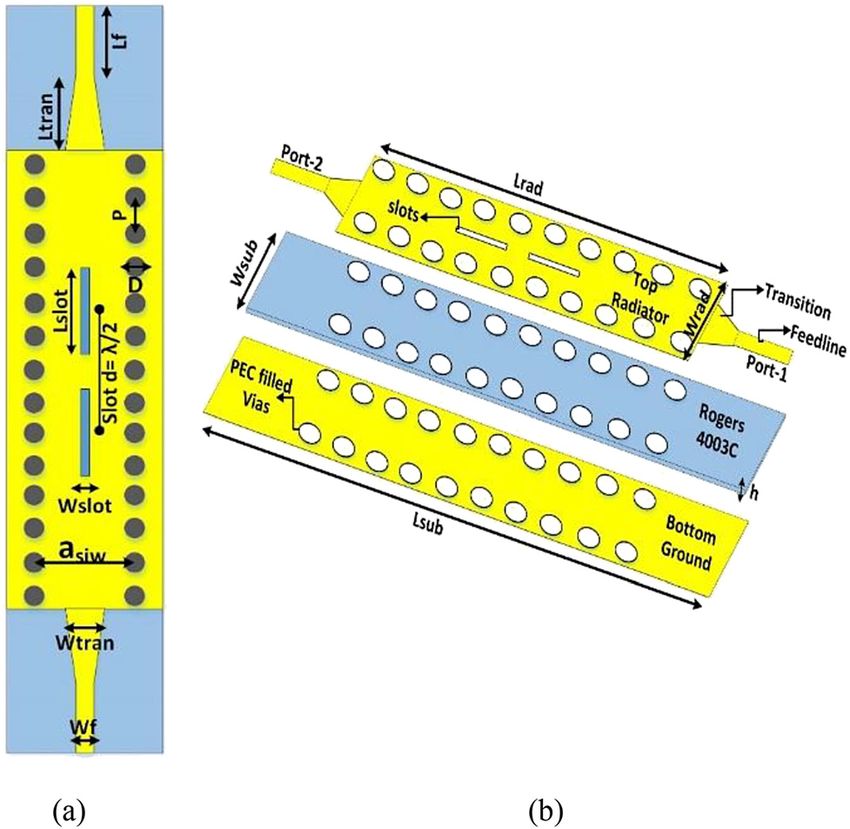
H. Vettikalladi et al.: 60 GHz beam tilting antenna 31
between 0.5 < DP < 0.8 [24]. A V-type connector is used to transmission plane is around −2 dB as per the standard
provide excitation to the design with the help of a acceptable level, for both the solvers. Figure 2 also depicts
microstrip-to-SIW transition. The optimized parameters of the solvers comparison via directivity plots for the whole
the proposed design are presented in Table 1. band of interest. The maximum directivity for both the
solvers at the center frequency of 60 GHz reached at
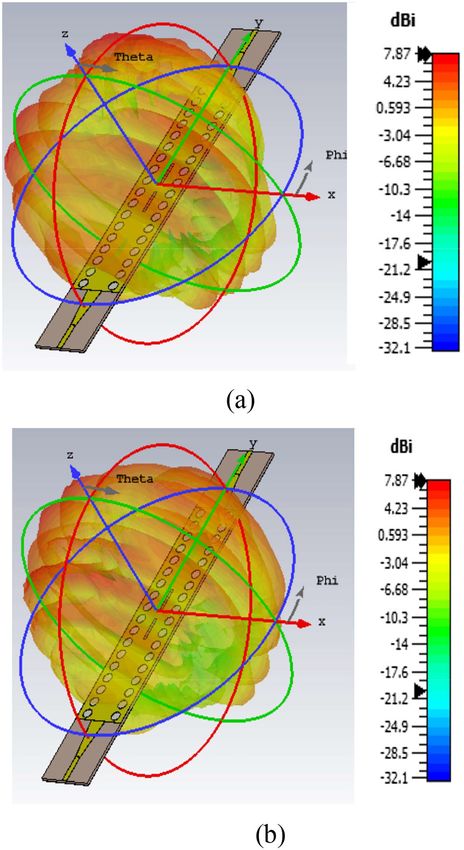
around 7.87 dBi respectively. For the radiation pattern,
2.2 Results and discussion Figure 3 depicts the directivity of the antenna. It can be
seen that the antenna is mostly radiating in the broadside
direction with some losses emerging from the bottom
Figure 2 presents the reflection coefficient (S11) of the
ground plane. These radiation losses are due to the
proposed 60 GHz open-ended waveguide SIW slot
selection of minimum height h of the antenna and surface
antenna design. Commercial electromagnetic (EM) simu-
lator (CST-MWS) was used to simulate the performance of losses as per via holes that produce side lobe levels of
around −5 dB. It should be noted here that this was the
the 60 GHz open-ended waveguide slotted antenna.
Comparison of results were done via the two electro- initial design considerations for 60 GHz open-ended
magnetic solvers (Transient and Frequency domain)
presents inside the CST simulator. It can be seen from the
Figure that the two-port antenna covers an impedance
bandwidth of 7 GHz (57–64 GHz) and beyond because
of its open-ended nature in the reflection coefficient plane
and below the reference line of −10 dB while the
Table : Optimised geometric parameters of the GHz Open-
ended antenna.
Parameters Value (mm) Parameters Value (mm)
Lrad Wtran .
Wrad Ltran
Lslot . Lsub
Wslot . Wsub
Asiw . D .
Lf P
Wf . h .
Figure 2: Reflection coefficient (S11) of the proposed 60 GHz open-
ended waveguide SIW slot antenna using CST-MWS with analysis via Figure 3: Directivity of proposed 60 GHz open-ended waveguide
Transient and Frequency domain solvers. SIW slot antenna. (a) Port-1, (b) Port-2.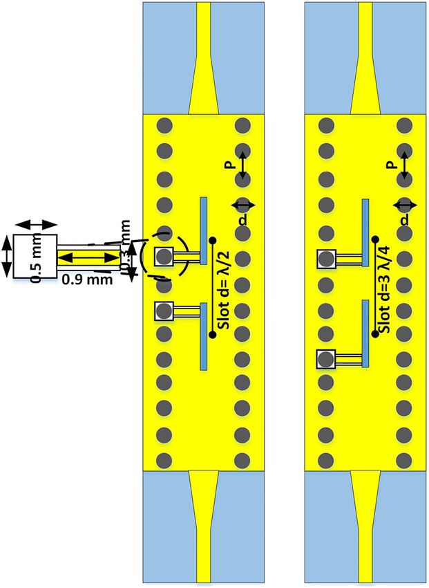
32         H. Vettikalladi et al.: 60 GHz beam tilting antenna

waveguide structure as a dual element and later on in the
upcoming sections, improvement will be noted in terms
of radiation pattern of the array structure and will be
presented.

3 Angular beam-tilting
3.1 Principle

Beam-tilting in most of the wireless systems is either
electronic or mechanical form. Electronic techniques uti-
lized systems like MEMS, RF microelectromechanical
systems, varactor diodes and transmission lines producing              Figure 4: Coplanar feed configurations with associated phase
precise beam-tilting with major drawbacks of losses in                 shifts.
gains and performance while beam steering. On the other
hand, the mechanical beam-tilting approach suffers from
the difficulty in installation due to the inclined structure of        excitations are required for these arrays. While to achieve
the antenna arrays. To find a nominal solution that doesn’t            Δφ = 45∘ , −45° or 135°. The radiant elements must be
involve electronic or mechanical tilting, we present a                 excited simultaneously by two feeders as shown in
method to beam-tilt the radiation pattern of the proposed              Figure 4. As a recall, this solution validates the principle of
antenna. The idea is based on utilizing the position of                obtaining different beam-tilts, by simply changing the slot
coplanar feeds and its associated via holes to excite the              associations.
passive rectangular slots. Each placement of coplanar feed
will correspond to a certain phase shift which will tilt the
beam at a certain angle. The coplanar feeds can be in a
single or dual manner per rectangular slot. Figure 4 shows
how the placement of coplanar feeds and respective dis-
tance between slots can provide a beam-tilt. Equation (3)
provides the mathematical formula to calculate the beam-
tilts;
                                     Δφ∗λ
                      θo = sin−1 (        )                      (3)
                                      2πd
where θo , Δφ, λ and d are beam-tilts, phase shift in radian,
center wavelength and distance between the slots respec-
tively. Various coplanar feeder positions are presented in
Figure 4 that determine desired equivalent phase shifts
[21]. In order to obtain Δφ = 0∘ , two different configurations
are proposed, the first one is an association of two slots
where the two coplanar feeders are spaced with one
guided-wavelength (i.e. corresponding to Δφ = 360∘ ), that
are oriented differently, one down and the other up. The
second array is also an association of two slots in upward
orientation, where their excitation parts are spaced by a
λg/2 which represent a phase opposition. This spacing and
the opposite phase correspond to Δφ = 180∘ for each, as a
result, a phase shift of 360° (i.e. 0°) is obtained as detailed
in Figure 4. Briefly, to get Δφ = 0∘ , 180°, 90° and −90°, the
central slots require only one excitation per element                  Figure 5: Two configuration of 60 GHz open-ended waveguide SIW
(see in Figure 4), here only slot associations with single             slot antenna (a) 0° phase shift (b) 90° phase shift.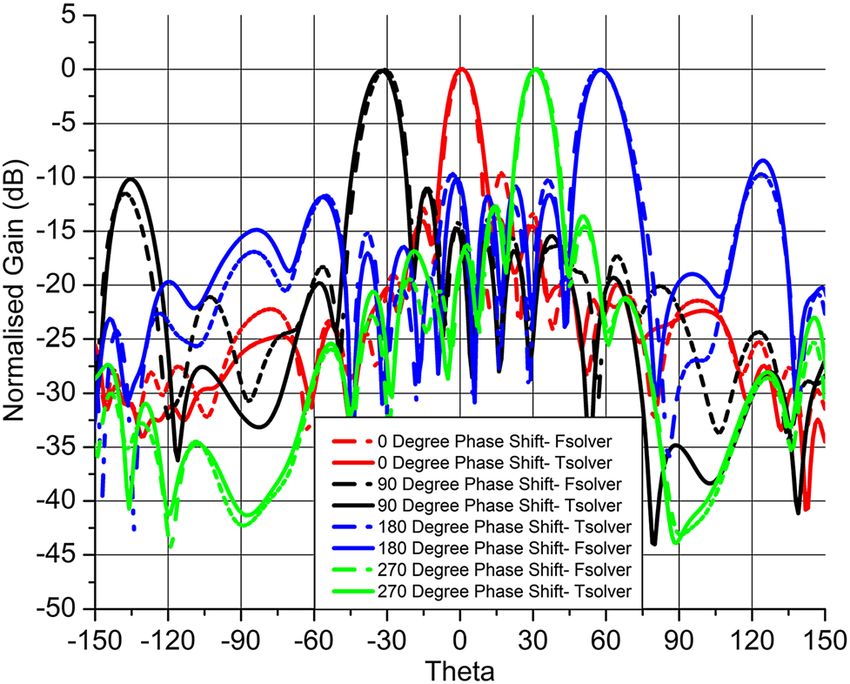
H. Vettikalladi et al.: 60 GHz beam tilting antenna 33
Figure 6: Reflection coefficient (S11) of the two proposed
configuration of 60 GHz open-ended waveguide SIW slot antenna
using CST-MWS with analysis via Transient and Frequency domain
solvers.
3.2 Two element SIW slotted array
configuration
To validate Figure 4 and observe the beam-tilt as per Figure 8: Four configuration each having 10-elements for the 60 GHz
open-ended waveguide SIW slot antenna (a) 0° phase shift (b) 90°
coplanar feed for slot placement, we present a two-port
phase shift (c) 180° phase shift (d) 270° phase shift.
analysis of already proposed 60 GHz open-ended wave-
guide slot design in Section 2. Figure 5 presents the two
proposed designs. The geometric dimensions have been Simulation results in terms of reflection coefficient
kept the same as listed in Table 1. The addition of two (S11) show the proposed antennas performance. From
coplanar feeding positions (0° phase shift and 90° phase Figure 6 it can be seen that the antenna maintains its
shift) are introduced to excite the rectangular slots having wideband impedance matching S11 characteristics at 7 GHz
dimensions as depicted in Figure 5. (57–64 GHz) below the reference line of −10 dB while the
transmission is around −2 dBi for the two-port design. The
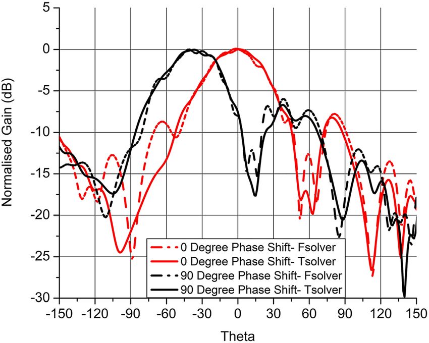
Figure 7: Simulated H-plane radiation pattern of the two proposed
configurations at 0° and 90° phase shift of 60 GHz open-ended Figure 9: Reflection coefficient (S11) of the four proposed configuration
waveguide SIW slot antenna using CST-MWS with analysis via of 60 GHz open-ended waveguide SIW slot antenna using CST-MWS
Transient and Frequency domain solvers. with analysis via Transient and Frequency domain solvers.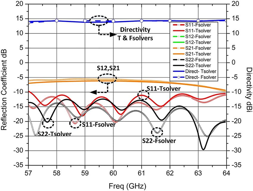
34 H. Vettikalladi et al.: 60 GHz beam tilting antenna
verification from another solver i.e. F-domain, the beam-
tilts for the 0° phase shift and 90° phase shift is −5° and −42°
respectively.
4 Ten element SIW slotted antenna
array
To further verify the performance of the proposed antenna in
terms of improved directivity and beam-tilting principle
as described in Figure 4 and Eq. (3), we propose four new
designs based on 10-element SIW slotted antenna array.
Figure 8 presents the four designs where the base geometric
dimensions are kept the same as listed in Table 1 while
the placement of the coplanar feed and associated vias
Figure 10: Simulated H-Plane radiation pattern of the four proposed
dimensions are the same as the inset shown in Figure 5. The
configurations at 0°, 90°, 180° and 270° phase shift of 60 GHz open-
ended waveguide SIW slot antenna using CST-MWS with analysis via
phase shift angles that would give us a beam-tilt are 0°, 90°,
Transient and Frequency domain solvers. 180° and 270°. The simulated reflection coefficient S11 of the
proposed design for the phase shift angles are presented in
Figure 9. It can be seen that a wide band matching is
Table : Phase shifts and their respective beam-tilts for the
proposed GHz open-ended SIW slot antenna. retained around 7 GHz (57–64 GHz) while some losses are
seen in the transmission coefficient values as decay hap-
Phase Beam-tilts Eq. () Beam-tilt Beam-tilt pens from −7 to −9 dB at the higher frequency bands.
shifts (T-solver) (F-solver) The normalized H-plane radiation pattern of the pro-
° ° ° -° posed 10-element antenna array is depicted in Figure 10. For
° −° −° −° the case of 0° phase shift (Figure 8a), the antenna achieves a
° ° ° ° gain of 12 dBi, side lobe levels SLL = −7.5 dB and beamwidth
° ° ° ° of 11.3°. For the second configuration of 90° phase shift
(Figure 8b), the antenna achieves a gain of 10.83 dBi, side
normalized H-plane radiation pattern for the two configu- lobe levels SLL = −10.1 dB and beamwidth of 13.4°. The third
rations are presented in Figure 7. For the case of 0° phase configuration of 180° phase shift (Figure 8c), achieves an
shift (Figure 5a), the antenna achieves a gain of 7.31 dBi, antenna gain of 8 dBi, side lobe levels SLL = −9.7 dB and
side lobe levels SLL = −8.1 dB and beamwidth of 49.5°. The beamwidth of 15.7° while the fourth configuration of 270°
main beam-tilt angle is at 0°. For the second configuration phase shift (Figure 8d), the antenna achieves a gain of 10.2
of 90° phase shift (Figure 5b), the antenna achieved a gain dBi, side lobe levels SLL = −9.6 dB and beamwidth of 11.2°.
of 8.06 dBi, side lobe levels SLL = −7.1 dB and beamwidth The effect of beam-tilting scenario among the four pro-
of 49.1°. The main beam-tilt angle is at −40°. In case of posed designs are listed in Table 2 where a comparison
Table : Phase shifts and their respective beam-tilts for the proposed GHz open-ended SIW slot antenna.
Ref Antenna type Feeding technology Bandwidth Gain Beam-tilting Beam-tilting technology Design
(GHz) (dBi) coverage (θ) layers
[] Slot fed circular Printed ridge gap – °, °, ° Phase gradient surfaces Stacked
patch waveguide
[] Circular patch Coaxial probe feed – . −° to ° NMOS switches Planar
[] Fabry Perot cavity Substrate integrated – . −°, °, ° Quasi curved reflector with Stacked
waveguide three feeding sources
[] Cavity backed Butler matrix network – . −° to ° Phase shifters utilizing SIW Stacked
crossed patch technology
This SIW rectangular Microstrip-to-SIW – −° to ° Slot excitation via coplanar fed Planar
work slots transition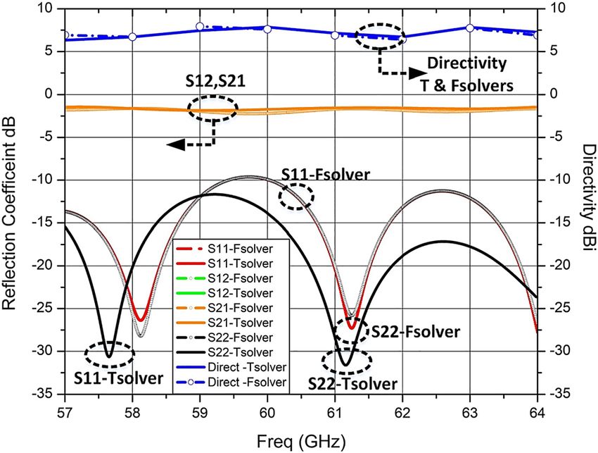
H. Vettikalladi et al.: 60 GHz beam tilting antenna           35

between the results obtained from the mathematical                     [2] K. A. Mekonnen, J. Zantvoort, N. Calabretta, et al., “High-capacity
formula of Eq. (3) and simulated results among the two                     dynamic indoor network employing optical-wireless and 60-GHz
                                                                           radio techniques,” J. Lightwave Technol., vol. 36, no. 10,
solvers i.e. Transient domain and Frequency domain are
                                                                           pp. 1851–1861, 2018.
presented. In order to provide a comparison of the pro-                [3] A. A. Baba, R. M. Hashmi, K. P. Esselle, et al., “Broadband
posed design with other available techniques, Table 3                      partially reflecting superstrate-based antenna for 60 GHz
lists the comparison based on different feeding tech-                      applications,” IEEE Trans. Antenn. Propag., vol. 67, no. 7,
nologies operating in the 60 GHz band.                                     pp. 4854–4859, 2019.
                                                                       [4] M. Riobó, R. Hofman, I. Cuiñas, et al., “Wideband performance
                                                                           comparison between the 40 GHz and 60 GHz frequency bands
                                                                           for indoor radio channels,” Electronics, vol. 8, no. 11, p. 1234,
5 Conclusion                                                               2019.
                                                                       [5] D. D. Rio, D. Yoon, F. T. Chen, et al., “Multi-Gbps tri-band 28/38/
                                                                           60-GHz CMOS transmitter for millimeter-wave radio system-on-
A beam-tilting technique without the use of active or passive              chip,” in IEEE MTT-S International Microwave Symposium (IMS),
phase shifters was presented in this work. A 60 GHz open-                  2019, pp. 488–491.
ended waveguide SIW slots coupled to coplanar feed was                 [6] M. J. Jeong, N. Hussain, J. W. Park, et al., “Millimeter‐wave
chosen as the proposed antenna design. The antenna was                     microstrip patch antenna using vertically coupled split ring
                                                                           metaplate for gain enhancement,” Microw. Opt. Technol. Lett.,
fed via a microstrip-to-SIW transition where the beam-tilting
                                                                           vol. 61, no. 10, pp. 2360–2365, 2019.
was achieved via various orientations of coplanar feed and
                                                                       [7] Y. J. Zhu, C. Chu, S. Li, et al., “Low-profile wideband and high-
its associated vias. The coplanar feed orientations produce                gain LTCC patch antenna array for 60 GHz applications,” IEEE
phase shifts that resulted in producing required beam-tilts.               Trans. Antenn. Propag., vol. 68, no. 4, pp. 3237–3242, 2019.
To validate the beam-tilting principle, initially a two SIW            [8] W. T. Sethi, A. Alfakhri, M. A. Ashraf, et al., “State-of-the-art
slot element design having phase shift of 0° and 90°                       Antenna Technology for Cloud Radio Access Networks (C-RANs),”
                                                                           in Cloud Computing-Architecture and Applications, Jaydip Sen,
was presented. Next, an improvement in designs radiation
                                                                           IntechOpen, 2017.
directivity was observed when a 10-element SIW slot an-                [9] W. T. Sethi, M. A. Ashraf, A. Ragheb, et al., “Demonstration of
tenna array with four phase shift configurations i.e. 0°, 90°,              millimeter wave 5G setup employing high-gain vivaldi array,”
180° and 270° was presented. The results were verified                      Int. J. Antennas Propag., vol. 2018, pp. 1–12, 2018.
with mathematical formulae as well as two simulators.                [10] G. Srivastava and A. Mohan, “A differential dual-polarized SIW
                                                                           cavity-backed slot antenna,” IEEE Trans. Antenn. Propag., vol.
The antenna produced an impedance bandwidth of 7 GHz
                                                                           67, no. 5, pp. 3450–3454, 2019.
(57–64 GHz) with gains reaching to 12 dBi. The 10-element
                                                                      [11] S. H. Zainud-Deen and H. A. E. A. Malhat, “Circularly polarized SIW
array without the need of active phase shifters covered an                 DRA fed by ridge gap waveguide for 60 GHz communications,”
area of −56° to 56° in a simplistic design approach.                       Wireless Pers. Commun., vol. 114, no. 1, pp. 113–122, 2020.
                                                                     [12] A. Dadgarpour, M. A. Antoniades, A. Sebak, A. A. Kishk,
Author contributions: All the authors have accepted                        M. Sharifi Sorkherizi, and T. A. Denidni, “High-gain 60 GHz linear
                                                                           antenna array loaded with electric and magnetic metamaterial
responsibility for the entire content of this submitted
                                                                           resonators,” IEEE Trans. Antenn. Propag., vol. 68, no. 5,
manuscript and approved submission.                                        pp. 3673–3684, 2020.
Research funding: This project was funded by the                     [13] P. Baniya and K. L. Melde, “Switched beam SIW horn arrays at 60
National Plan for Science, and Technology and                              GHz for 360° chip-to-chip communications,”in 2021 IEEE Radio
innovation (MAARIFAH), King Abdulaziz City for                             and Wireless Symposium (RWS), 2021, pp. 39–42.
                                                                     [14] Y. W. Wu, Z. C. Hao, and Z. W. Miao, “A planar W-band large-scale
Science and Technology, Kingdom of Saudi Arabia,
                                                                           high-gain substrate-integrated waveguide slot array,” IEEE
Award number (13-ELE1184-02-R).
                                                                           Trans. Antenn. Propag., vol. 68, no. 8, pp. 6429–6434, 2020.
Conflict of interest statement: The authors declare that they         [15] S. N. Suhaimi and N. M. Mahyuddin, “Review of switched
have no known competing financial interests or personal                     beamforming networks for scannable antenna application
relationships that could have appeared to influence the                     towards fifth generation (5G) technology,” Int. J. Integrated Eng.,
work reported in this paper.                                               vol. 12, no. 6, pp. 62–70, 2020.
                                                                     [16] H. Ren, P. L. Yixin Gu, and B. Arigong, “Phase shifter-relaxed and
                                                                           control-relaxed continuous steering multiple beamforming 4 × 4
                                                                           butler Matrix phased array,” in IEEE Transactions on Circuits and
References                                                                 Systems I: Regular Papers, 2020.
                                                                     [17] M. A. Abbasi, V. Fusco, and M. Matthaiou, “Millimeter wave
[1] M. A. Jamshed, F. Heliot, and T. W. C. Brown, “A survey on             hybrid beamforming with Rotman lens: performance with
    electromagnetic risk assessment and evaluation mechanism for           hardware imperfections,” in IEEE 16th International Symposium
    future wireless communication systems,” IEEE J. Electromag. RF         on Wireless Communication Systems (ISWCS), 2019,
    Microw. Med. Biol., vol. 4, no. 1, pp. 24–36, 2019.                    pp. 203–207.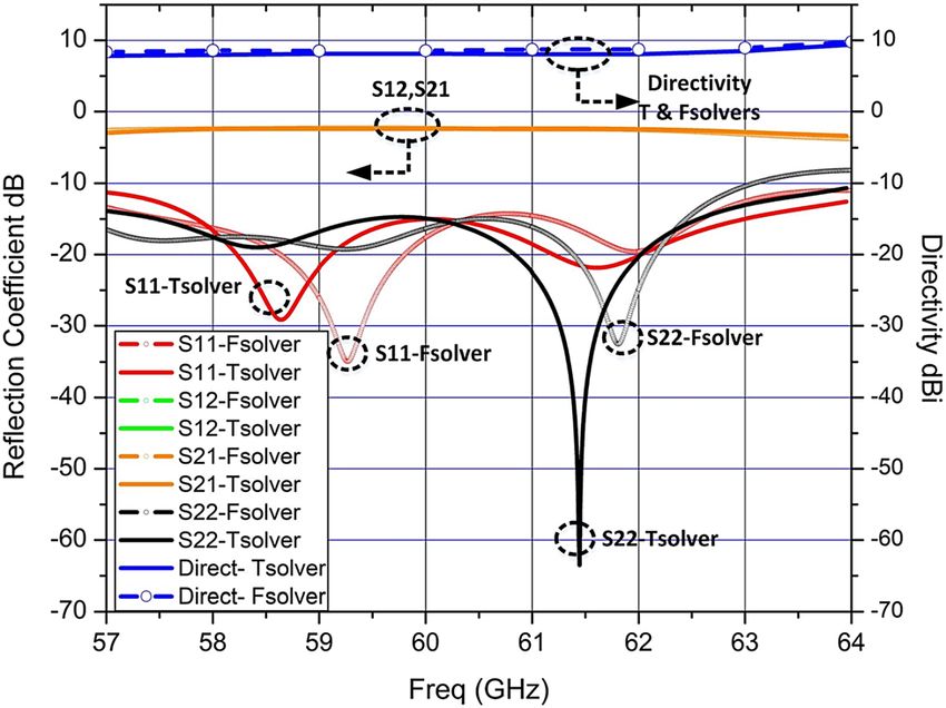
36          H. Vettikalladi et al.: 60 GHz beam tilting antenna

[18] S. Dey, S. K. Koul, A. K. Poddar, et al., “RF MEMS switches,           [24] Z. Kordiboroujeni and J. Bornemann, “Designing the
      switching networks and phase shifters for microwave to                     width of substrate integrated waveguide structures,” IEEE
      millimeter wave applications,” ISSS J. Micro Smart Syst., vol. S9,         Microw. Wireless Compon. Lett., vol. 23, no. 10, pp. 518–520,
      no. 1, pp. 33–47, 2020.                                                    2013.
[19] R. R. Turjo, S. M. Real, and Md. H. Sagor, “Phased array antenna       [25] M. Akbari, M. Farahani, A. Ghayekhloo, S. Zarbakhsh, A. Sebak,
      with key shaped elements for 60 GHz mmWave                                 and T. A. Denidni, “Beam tilting approaches based on phase
      communications,” in 2019 International Workshop on Antenna                 gradient surface for mmWave antennas,” IEEE Trans. Antenn.
      Technology (iWAT), IEEE, 2019, pp. 178–181.                                Propag., vol. 68, no. 6, pp. 4372–4385, 2020.
[20] J. Li and D. Chu, “Liquid crystal-based enclosed coplanar              [26] Y. I. A. Al-Yasir, H. A. H. Al-Behadili, B. A. Sawadi, et al., “New
      waveguide phase shifter for 54–66 GHz applications,” Crystals,             radiation pattern-reconfigurable 60-GHz antenna for 5G
      vol. 9, no. 12, p. 650, 2019.                                              communications,” inModern Printed-Circuit Antennas, Hussain
 [21] I. Serhsouh, M. Himdi, and H. Lebbar, “Design of coplanar slotted          Al-Rizzo, IntechOpen, 2019.
      SIW antenna arrays for beam-tilting and 5G applications,” IEEE        [27] Q. Guo and H. Wong, “Wideband and high-gain Fabry–Pérot
      Antenn. Wireless Propag. Lett., vol. 19, no. 1, pp. 4–8, 2020.             cavity antenna with switched beams for millimeter-wave
[22] CST Studio Suite, CST Microwave Studio, 2019. http://www.cst.               applications,” IEEE Trans. Antenn. Propag., vol. 67, no. 7,
      com.                                                                       pp. 4339–4347, 2019.
[23] G. Venanzoni, D. Mencarelli, A. Morini, et al., “Review of substrate   [28] J. Zhu, B. Peng, and S. Li, “Cavity-backed high-gain switch beam
      integrated waveguide circuits for beam-forming networks working            antenna array for 60-GHz applications,” IET Microw. Antennas
      in X-band,” Appl. Sci., vol. 9, no. 5, p. 1003, 2019.                      Propag., vol. 11, no. 12, pp. 1776–1781, 2017.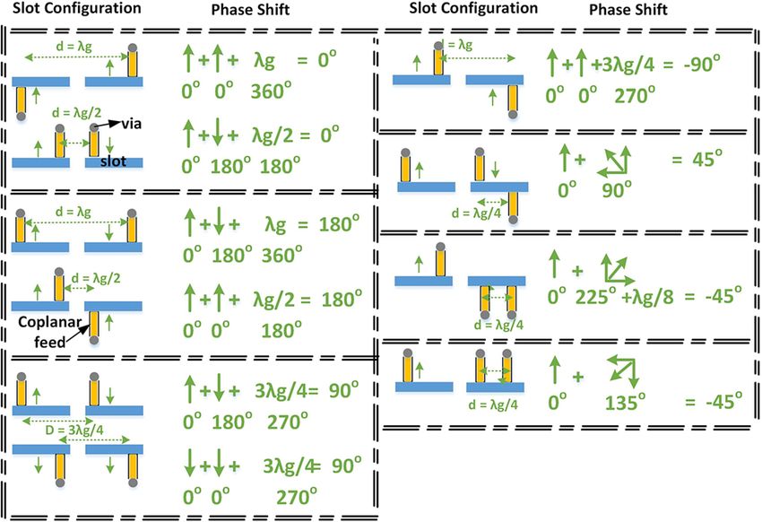
You can also read