Adaptive Radio Modes in Sensor Networks: How Deep to Sleep?
←
→
Page content transcription
If your browser does not render page correctly, please read the page content below
1

          Adaptive Radio Modes in Sensor Networks:
                    How Deep to Sleep?
                                 Raja Jurdak, Antonio G. Ruzzelli, Gregory M. P. O’Hare
                                       School of Computer Science and Informatics,
                                                 University College Dublin
                                       {raja.jurdak, ruzzelli, gregory.ohare} @ucd.ie

   Abstract—Energy-efficient performance is a central challenge      cost and the longest latency for switching the radio back to
in sensor network deployments, and the radio is a major              active mode. In contrast, the lightest sleep mode provides a
contributor to overall energy node consumption. Current energy-      transition to active mode that is quick and energy inexpensive,
efficient MAC protocols for sensor networks use a fixed low power
radio mode for putting the radio to sleep. Fixed low power modes     but it has a higher current draw. In a low traffic scenario, it is
involve an inherent tradeoff: deep sleep modes have low current      better to use the deep sleep mode as nodes spend more time
draw and high energy cost and latency for switching the radio to     sleeping than switching back and forth between sleep mode
active mode, while light sleep modes have quick and inexpensive      and active mode. In a high traffic scenario, a lighter sleep mode
switching to active mode with a higher current draw. This paper      is more suitable as the cost of switching the radio frequently
proposes adaptive radio low power sleep modes based on current
traffic conditions in the network, as an enhancement to our recent   into deep sleep mode would exceeds the energy saving of the
RFIDImpulse low power wake-up mechanism. The paper also              deep sleep mode’s low current draw.
introduces a comprehensive node energy model, that includes             To address this tradeoff, this paper proposes adaptive radio
energy components for radio switching, transmission, reception,      low power sleep modes that dynamically change according
listening, and sleeping, as well as the often disregarded micro-     to current traffic conditions in the network. To demonstrate
controller energy component to evaluate energy performance
for both MicaZ and TelosB platforms, which use different             the benefits of adaptive sleep modes, we incorporate them
MCU’s. We then use the model for comparing the energy-related        into our recently proposed RFIDImpulse mechanism [12],
performance of RFIDImpulse enhanced with adaptive low power          which uses RFID tags as an out-of-band wake up radio
modes with BMAC and IEEE 802.15.4 for the two node platforms         for sensor networks [1], [11], and compare its performance
under varying data rates. The comparative analysis confirms that     against the popular BMAC [4] protocol and the IEEE 802.15.4
RFIDImpulse with adaptive low power modes provides up to 20
times lower energy consumption than IEEE 802.15.4 in low traffic     standard [14] across two pervasive sensor node platforms,
scenario. The evaluation also yields the optimal settings of low     namely MicaZ [6] and TelosB [7].
power modes on the basis of data rates for each node platform,          The performance evaluation of proposed protocols generally
and it provides guidelines for the selection of appropriate MAC      considers the radio energy consumption, including receiving,
protocol, low power mode, and node platform for a given set of       transmitting, listening, and sleeping energy consumption com-
traffic requirements of a sensor network application.
                                                                     ponents, but it disregards the switching energy component [13]
                                                                     that is appreciable for any protocol that switches nodes be-
                      I. I NTRODUCTION                               tween active and sleep modes in low traffic conditions. While
   Energy-efficient performance is a central challenge in sensor     in some cases protocol evaluations consider the sensor energy
network deployments, as battery replacement is costly and            consumption, they also often ignore the energy consumption
often difficult in inaccessible deployment regions. Several          at the micro-controller unit (MCU). Disregarding MCU power
efforts have addressed the energy efficiency, through the            consumption typically stems from two assumptions: (1) that
design of energy saving MAC protocols, such as duty cycling          sensor networks are homogeneous and use the same node
protocols [4] or low power wake-up radio protocols [9], and          platform, in which case the MCU power component does not
routing protocols, such as [8].                                      affect relative power consumption among nodes or protocols;
   Radio energy consumption is a major component contribut-          and (2) that MCU power consumption is negligible relative to
ing to the overall energy consumption at each node. Current          radio power consumption. However, MCU power consump-
MAC protocols put the radio in sleep mode while there is             tion becomes relevant for heterogeneous sensor networks that
no data to send or receive, in order to minimize energy              include multiple node platforms or for choosing suitable node
consumption. Although common radios for sensor networks              platforms and protocols for a particular application scenario.
support multiple sleep modes, the radio sleep mode in current           In order to determine how to adapt low power modes
MAC protocols is static. Choosing a static low power mode            in RFIDImpulse and to compare the MAC protocols fairly
involves an energy and delay tradeoff. For example, the              across different platforms, this paper presents a sensor node
CC2420 [3] radio provides three different radio low power            energy consumption model that includes switching energy
modes. The deepest sleep mode, which turns off the oscillator        and micro-controller energy components. The model enhances
and voltage regulator, provides the lowest current draw of all       existing models [4], is generalizable to any MAC protocol and
low power modes. However, it also involves the highest energy        node platform, and serves as the basis for the performance
2

evaluation in this paper. For the evaluation, we have measured     block of low power listening in the pervasive TinyOS-1.x
the current draw of the CC2420 radio, which is used in both        operating system.
TelosB and MicaZ, in each of it operating modes, and we
use the measured values for comparing the protocols. The           B. IEEE 802.15.4
comparison of the protocols yields guidelines for selecting
                                                                      The 802.15.4 standard [14] provides MAC and PHY layer
appropriate MAC protocols and node platforms for specific
                                                                   specifications for low data-rate and energy-efficient wireless
traffic requirements of an application. We also determine the
                                                                   networks. The MAC layer specifics include a beacon-enabled
optimal radio low power mode within RFIDImpulse as the
                                                                   mode and a non-beacon enabled mode. The beacon-enabled
data rate varies.
                                                                   mode represents an overkill and does not perform well in
   In sum, the novel contributions of this paper are four-fold:
                                                                   long-term monitoring application, so we focus here on the non-
   • Proposal of adaptive radio low power sleep modes within
                                                                   beacon enabled mode. In non-beacon enabled mode, no bea-
      our previously proposed RFIDImpulse protocol that can        cons are broadcast, so 802.15.4 reduces to plain CSMA/CA.
      dynamically change based on network or node traffic             Nodes use a binary exponential back-off mechanism to
   • Introduction of an analytical energy model that considers
                                                                   resolve collisions, with the variable BE defining the number of
      radio energy consumption, including transmission, recep-     slots during each back-off period. Figure 1 shows the backoff
      tion, listening, sleeping, and switching energy compo-       structure of IEEE 802.15.4 with BE initially set to 3. Thus, any
      nents, and micro-controller energy consumption as an         node with data to send selects a random time slot R1 during
      enabler for comparing protocols across node platforms        the first 2BE − 1 = 7 time slots. The node then performs a
      that use different processor boards.                         clear channel assessment (CCA) during the timeslot R1 . If it
   • Energy-efficiency evaluation of BMAC, 802.15.4, and
                                                                   detects no activity on the channel, then the node assumes the
      RFIDImpulse across 2 popular node platforms, MicaZ           channel is free of carriers, so it reserves the channel for this
      and TelosB. The evaluation considers the dependence of       time slot. Otherwise, if the channel is busy during time slot
      energy-efficiency and optimal power mode on data rate.       R1 , then the node backs off, increments BE by 1, and selects
   • Provision of guidelines based on the evaluation results for
                                                                   a random time slot R2 during the next 24 − 1 = 15 time slots.
      MAC protocol, power mode, and node platform selection        The CCA process is repeated, and in case R2 is also busy, then
      according to the expected traffic requirements of the        the node repeats the process again for BE=5 to select R3 . If
      target application.                                          R3 is free, then the node sends its data during R3 . Otherwise,
   The remainder of the paper is organized as follows. Sec-        it drops the packet.
tion II presents the details of BMAC, IEEE 802.15.4 and
the adaptive low power mode version of RFIDImpulse, while
                                                                   C. RFIDImpulse
Section III provides the analytical model for evaluating the
energy benefits of the three protocols. Section IV evaluates          RFIDImpulse is a very low power radio wake-up scheme
the performance of the three protocols for MicaZ and TelosB        for sensor networks that relies on off-the-shelf RFID readers
in a multi-hop network, and section V discusses the results        and tags. The basic functionality of RFIDImpulse is shown in
and concludes the paper.                                           Figure 2. All network nodes turn off their radios, including
                                                                   the voltage regulator and the oscillator, as long as they have
                    II. MAC P ROTOCOLS                             no packets to send or receive. The nodes also put their micro
                                                                   controller units (MCU) in power down mode during this idle
  This section presents the three protocols under consideration
                                                                   period. A node that wishes to send a packet uses a built-in
separately: BMAC, IEEE 802.15.4 and RFIDImpulse.
                                                                   RFID reader to trigger an RFID tag that is located at the
                                                                   remote sensor node. The impulse from the sender causes the
A. BMAC                                                            RFID tag at the intended receiver, which is connected to the
   BMAC [4] is an asynchronous and lightweight sensor net-         external interrupt pin of the micro-controller at that node, to
work MAC protocol that aims at providing versatile medium          generate an interrupt to wake up the MCU. The MCU wakes
access while keeping the MAC functionality as simple as            up and activates the radio voltage regulator and oscillator in
possible. As an asynchronous protocol, BMAC eliminates the         preparation for the incoming packets. After a short start up
communication and processing overhead for scheduling and           time of few milliseconds for the radio components, the radio
synchronization, which reduces energy consumption. BMAC            at the receiver becomes fully active. At this point, the sender
enables each node to wake up periodically to check for             commences the transmission. Once the sender completes all
channel activity. The wake-up period is referred to as the         its packet transmissions, both sender and receiver again turn
check interval. BMAC defines 8 check intervals, and each           off their radios and MCU’s.
check interval corresponds to one of BMAC’s 8 listening               Because certain RFID standards operate in the ISM band,
modes. To ensure that all packets are heard by neighboring         which is the same band as the IEEE 802.15.4, an 802.15.4
nodes, packets are sent with a preamble whose reception time       radio, in addition to serving as a general-purpose communi-
is longer than the check interval. BMAC therefore defines          cation radio [10], can potentially activate a remote passive
8 different preamble lengths referred to as transmit modes.        RFID tag through an energy harvesting strategy (such as with
Although several optimizations have improved over BMAC             a suitable comparator [9]), which in turn drives the activation
since its release, we consider it here as it still the building    of the sensor node. Although RFIDImpulse is independent
3
Fig. 1. Binary Exponential Backoff in IEEE 802.15.4
If there is still no packets, the radio stays on for another 31
time units, at which point the node either has started receiving
the packet, or can go back into sleep mode. The maximum
listening duration during an awake interval is therefore 54 time
units that corresponds to about 17 ms.
IEEE 802.15.4-compliant radios, such as CC2420, support
three low power modes in addition to the active mode. The
deepest sleep mode (M3) turns off the oscillator and voltage
regulator, which minimizes radio energy consumption. Nodes
that use M3 as a sleep mode must wait for about 2.4 ms
every time they turn the radio back on, and the operation of
switching the radio from mode M3 to active mode involve
appreciable energy cost [13]. In contrast, the lightest sleep
mode in the CC2420 (M1) provides much quicker switching
back to active mode (30µs) and much cheaper switching
Fig. 2. High level timeline of RFIDImpulse
energy cost. However, the energy consumption of a node while
its radio is in M1 sleeping state is significantly higher than
mode M3. This exposes an energy and delay tradeoff between
of the underlying MAC protocol, in the following discussion how deep a node sleeps and how often it wakes up to send or
we describe how RFIDImpulse can enhance 802.15.4 MAC receive packets. We mainly focus here on the energy tradeoff,
operation while maintaining compliancy with the standard. leaving the details of delay-based selection of radio sleep mode
The non-beacon enabled mode in 802.15.4 demands that as an open research direction for future work.
nodes wake up periodically for a contention access period in To address the energy tradeoff, RFIDImpulse supports
order to avoid keeping the nodes awake all of the time. With traffic-based selection of low power radio modes, as a mech-
RFIDImpulse, a node can put its radio and MCU in sleep mode anism of managing energy and delay tradeoffs of putting the
as long as it has no data to send and as long as its RFID tag radio to sleep. When the traffic load is high in a particular
has not been triggered. A node typically has data to transmit region of the network, nodes use lighter sleep modes as they
either when it has just sampled its sensors, or when it has to have to wake up frequently to send and receive packets. It
receive a packet that requires forwarding. In the latter case, the is not worthwhile for nodes to go into deeper sleep modes
node is already awake and can attempt to forward the packet due to the higher latency and switching energy involved in
immediately. If the node has a packet to send due to a sensing frequent wake up transitions. When the traffic load is low in a
event, the sensor output can generate an external interrupt at particular region of the network, switching between sleep and
the MCU, in addition to the RFID tag, which enables sensing active states is less frequent, so nodes use deeper sleep modes
events to trigger a wake up event of an MCU in deep sleep. that provide that highest energy savings.
Once the MCU is awake, it activates the radio. The radio then
performs CCA, as in 802.15.4, in a random byte slot within the III. A NALYTICAL M ODEL
first 7 slots. In case the selected slot is busy, then the sender In order to model the energy consumption of the three MAC
backs off, goes into idle mode, and listens to the channel again protocols, this section considers all the energy components
in a random byte slot within the next 15 slots and so on. that contribute to the overall energy consumption at a node,
As a receiver, the node sleeps until its RFID tag is triggered. including the micro-controller unit and radio activity. We
The node MCU is then activated through an external interrupt consider a convergecast application where all nodes sample
generated by the tag, and then the MCU turns on the radio. The their sensor periodically and send the data towards the base
node then listens to the channel exactly as in IEEE 802.15.4. station. In this application, the sensing activity is the same for
If it does not receive any packets destined for it during the first all nodes and protocols, so we disregard this energy component
7 time units, it stays awake for an additional 15 time units. for the protocol comparisons.4
A. Microcontroller Unit Energy Finally, the total node listening energy for RFIDImpulse can
The energy consumption at the micro-controller unit of be expressed as:
sensor motes contributes significantly to energy consumption, rf id
Elisten = Esend × Psent + Erecv × Precv (6)
yet this energy component is often disregarded when analyzing
the energy consumption of sensor network communication where Psent and Precv are the number of packets sent and
protocols. While most protocols keep the MCU in standby received at the node.
mode when the node is idle, RFIDImpulse enables the MCU
to go into power down mode and be awoken only through an
external interrupt through the onboard RFID tag. As such, the C. Switching Energy
MCU energy consumption while the node is idle:
The switching energy component [13] is the energy con-
of f of f of f
Emcu = Tmcu × Imcu ×V (1) sumed for switching the radio state between states, including
of f
normal, power down, and idle modes. The following equation
where Tmcu is the total time during which the MCU is off, determines the energy consumed for switching the radio from
of f
Imcu is the current draw of the MCU while the node is idle, sleep mode α to active mode:
of f
and V is the supply voltage. The value of Imcu is the power
pd
down current Imcu for RFIDImpulse and the standby current α (Iactive − Iα ) × Tα × V
sb Eswitch = (7)
Imcu for other protocols. The MCU energy consumption 2
during active mode is:
where Iactive is the current draw of the radio in active mode,
on on on Iα is the current draw of the radio in sleep mode α, and Tα
Emcu = Tmcu × Imcu ×V (2)
on
is the time required for the radio to go from sleep mode α to
where Tmcu is the total time during which the MCU is on, active mode.
on
and Imcu is the MCU current draw during normal operation The switching energy consumption of duty cycling protocols
mode. The total MCU energy consumption, then, is simply the relates to the length of the sampling period and the check
of f on
sum of Emcu and Emcu . interval. For a fixed check interval, the number of times that a
node switches its radio on and off is proportional to the length
B. Listening Energy of the channel sampling period. More specifically:
We define the listening energy as the radio energy consump- S
dut α
tion when the radio is active but not receiving or sending any Eswitch = × 2 × Eswitch (8)
CK
packets. Protocols that are based on low power listening, such
as BMAC [4], have the following listening energy: The factor of 2 in the above equation accounts for switching
back to mode α from active mode.
lpl S
Elisten = × TCH × Ilisten × V (3) In RFIDImpulse, the switching energy does not depend on
CK the sampling period, but it depends on the number of packets
where S is the sampling period, CK is the check interval, sent and received. As a receiver, a node switches from sleep
TCH is the time during which the node is awake every cycle, mode to active mode whenever its tag is activated, and it stays
and Ilisten is the current draw of the radio in listening mode. awake for a maximum of 54 time units during the contention
In contrast, the listening energy in RFIDImpulse only de- period. As a sender, a node switches from sleep to active mode
pends on the number of packets to be sent or received, and to perform CCA. If the channel is busy, then the node goes
not on the sampling period. A sender wakes up the intended into idle mode until the next back-off interval. This process
receiver through the RFID tag, and then follows the IEEE may be repeated up to a maximum of 3 times. Thus, the total
802.15.4 CCA and collision avoidance mechanism described switching energy at a single node in RFIDImpulse is:
in Section II-B. Considering the worst case in which the packet
rf id α idle α
is sent, the sender performs CCA three times before finding a Eswitch = 2×[Psent ×(Eswitch +3×Eswitch )+Precv ×Eswitch ]
free slot. During all the other 51 time slots, the sender radio (9)
can go into idle mode, so the listening energy consumption
per packet sent is:
D. Transmission Energy
Esend = (3 × TCCA × Ilisten + 51 × TCCA × Iα × V ) (4)
The transmission energy component refers to the energy
where TCCA is the CCA duration, α is the radio sleep mode consumed for transmitting packets and their associated control
in use that is equal to M1 for idle mode, and Iα is the current overhead on the radio. During any time period, the transmis-
draw of the radio while idle. Whenever the receiver tag in sion energy is expressed as:
RFIDImpulse activates the MCU, and then the radio, the radio
must stay on while the sender is attempting to transmit, which Et = Psent × Plength × TB × It × V (10)
in the worst case is 54 time units. Thus, the listening energy
per packet received in RFIDImpulse is: where Plength is the length of a packet in bytes, It is the
current draw of the radio while in transmit mode, and TB is
Erecv = 54 × TB × Ilisten × V (5) the time for sending one byte over the radio.5
Protocol Parameter Value Units
E. Receiving Energy All Supply Voltage (V) 3 V
Active Atmel MCU current (Imcuon ) 12 mA
The reception energy component refers to the energy con- on )
Active MSP MCU current (Imcu 0.35 mA
sumed while receiving packets and their associated control Listening Mode Current (Ilisten ) 18.8 mA
overhead on the radio. During any time period, the reception Transmit Mode Current (It ) 17.4 mA
energy is expressed as: Receive Mode Current (Ir ) 19.7 mA
Clear Channel Assessment ((TCCA ) 128 µSec
Er = Precv × Plength × TB × Ir × V (11) Sleep Current (I α ) α=M3 0.2 mA
Active Radio Current Iactive 19.7 mA
Byte Transmission Time (TB ) 32 µSec
where Ir is the current draw of the radio while receiving. of f
Duty Cycling Inactive Atmel MCU Current (Imcu ) 4.1 mA
of f
Inactive MSP MCU Current (Imcu ) 75 µA
of f
F. Sleeping Energy RFIDImpulse Inactive Atmel MCU Current (Imcu ) 0.25 mA
of f
Inactive MSP MCU Current (Imcu ) 6 µA
The sleeping energy component is simply the energy con- Sleep Current (I α ) α=M1 1 mA
sumption while the radio is in low power mode. The following Sleep Current (I α ) α=M2 0.5 mA
equation computes the sleeping energy for a node that goes Active Radio Current Iactive 19.7 mA
idle
Idle Switching Energy (Eswitch ) 827 nJ
into sleep mode α when it is off: BMAC Check Interval (CK) 10 mSec
of f Check Time (TCH ) 128 µSec
Esleep = Trf × Iα × V (12) IEEE 802.15.4 Check Interval (CK) 50 mSec
Check Time (TCH ) 17.28 mSec
The energy model described in this section provides the
basis for evaluating energy performance, protocol tradeoffs, TABLE I
S IMULATION PARAMETERS
and node platforms for varying traffic loads in the next section.
IV. P ERFORMANCE E VALUATION
MCU. Nodes can also put their radio in idle mode (M1)
This section explores the inter-dependencies among MAC
or medium sleep mode (M2) based on traffic activity in the
protocols, node platforms, and traffic load in sensor networks.
network. Nodes always use idle mode during the contention
In particular, we consider three MAC protocols: (1) the widely
period when they are about to send or receive a packet. In
used BMAC protocol; (2) the standard IEEE 802.15.4 MAC
contrast, both BMAC and IEEE 802.15.4 require that the MCU
protocol; and (3) RFIDImpulse. The performance evaluation
remains in standby mode when the radio is asleep with a low
here considers two widely used target platforms, namely the
speed oscillator running, in order to maintain system timers
TelosB and the MicaZ platforms. TelosB uses an MSP 430
and scheduled interrupts.
processor and a CC2420 radio [3], while MicaZ uses the same
With regards to check interval, we set this parameter to
radio with an Atmel128 [2] processor.
10ms for BMAC to accommodate high traffic scenarios, as
The first part of this section exposes the energy tradeoffs
recommended in [4]. During each check interval, the radio
of the three MAC protocols for a low sampling rate multi-
only stays active for a CCA period, and goes back into
hop scenario and a high sampling rate multi-hop scenario. We
mode M3 if no activity is detected on the channel. For IEEE
obtain results for each of the target node platforms separately.
802.15.4, the radio must stay awake for up to 54 time units or
The goal of these simulations is to expose the dominant energy
17.28 ms every check interval, so we set the check interval to
components for each protocol on the basis of traffic load
50 ms for 2 reasons: (1) to keep in line with BMAC listening
and node platform. Building on these results, the second part
modes that provide a check interval of 10, 20, 50, 100, 200,
of this section determines the energy consumption of each
400, 800, or 1600 ms; and (2) to ensure that the node can sleep
MAC protocol based on traffic load, and identifies the best
for a worthwhile period of time prior to waking up for another
performing protocol for each node platform and traffic load.
contention period. The data payload size in all simulations is
Table I summarizes all the simulation parameters, while
100 bytes, while the preamble length are as follows: 4 bytes for
distinguishing between common simulation parameters for all
RFIDImpulse to send the RFID address; 364 bytes for the long
protocols, parameters for duty cycling protocols that include
preamble in BMAC to match the 10 ms check interval; and
BMAC and IEEE 802.15.4, and parameters that are specific
16 bytes for the 802.15.4 non-beacon enabled mode header.
to each protocol. All of the parameters relating to the CC2420
Finally, note the lower current draw for MSP430 relative
radio are based on measurements we have conducted with
ATMEL128 processors for active, idle and power down modes.
an oscilloscope to determine the current draw and transition
The reduced MSP430 current draw results in lower MCU
latency for each power mode. All of the MCU-specific pa-
power consumption, reducing the impact of Emcu on protocol
rameters have been obtained from the respective data sheets
performance with this platform.
of the MSP430 datasheet for the TelosB platform and the AT-
MEL128 platform for the MicaZ platform. We now highlight
the main differences in the parameters for the protocols. A. Energy Tradeoffs
RFIDImpulse enables a node to put both its radio and We first explore the energy tradeoffs of the three protocols
microprocessor in the deepest sleep mode (M3) when the mentioned above. In this evaluation, we consider a network
node has no communication activity. Nodes can be awoken with a 6-hop binary tree static topology. Although the topology
by an external interrupt from the RFID tag attached to the of an actual sensor network can be both irregular and transient6
Fig. 4. Power consumption tradeoffs for TelosB at a sampling period of 100
Fig. 3. Power consumption tradeoffs for MicaZ at a sampling period of 100 seconds
seconds
the MCU to go into power down mode and to wake up through
according to environmental conditions as well as location, an external interrupt generated with the attached RFID tag.
this study serves as a representative case that exposes the The results also show that the energy consumption of all
energy tradeoffs of the three MAC protocols for the MicaZ three protocols does not have a significant dependance on the
and TelosB platforms under varying traffic loads. The network node’s hop count from the base station. To explain this trend,
is convergecast in nature where all nodes periodically sample we refer to the three pie charts in the lower part of Figure 3
their sensors and send the data in a packet towards the base that break down the energy consumption of nodes at hop count
station that is co-located with the root of the tree topology. 1 (the critical nodes) for each protocol.
Packets are forwarded in a multi-hop fashion until they reach For all three protocols, the energy consumption of the MCU
the base station. Each node’s hop count from the root in the represents a major portion of overall energy consumption.
logical topology determines its forwarding load. Intermediate In RFIDImpulse, Emcu is high because the MCU is awake
nodes must forward all packets of their children, while leaf more often the radio, both during the back-off period and
nodes only send their own packets. whenever the RFID tag is triggered and the radio is in
The first scenario considers the energy tradeoffs in a six hop transition between states. In both BMAC and IEEE 802.15.4,
binary tree network with a low data rate, in which the sampling the MCU is always in standby mode when the radio is in
period S is set to 100 seconds. Because of the low traffic load mode M3, which causes Emcu to be relatively high. Notably,
in this scenario, RFIDImpulse uses the deepest sleep mode the switching energy component, which is often disregarded
M3. Figure 3 shows the energy tradeoffs corresponding to in MAC protocol evaluations, accounts for about half of the
RFIDImpulse-M3, BMAC and IEEE 802.15.4 for the MicaZ overall energy consumption for BMAC. The high switching
platform. The bar graph in Figure 3 illustrates the energy energy for BMAC is due to the 10ms check interval which
consumption of nodes at each level within the tree network for causes the node to switch between active and sleep mode
each of the three protocols. In this scenario, the overall energy 10,000 times during the 100 second sampling period. In
consumption of RFIDImpulse-M3 is about 20 times lower than IEEE 802.15.4, El accounts for almost half the overall energy
for IEEE 802.15.4 and about 13 times lower than BMAC at consumption, as nodes must stay awake for up to 54 TB every
all levels of the topology. Both BMAC and IEEE 802.15.4 time they wake up, in contrast to the TCCA of BMAC.
require the nodes to wake up periodically to check the channel Figure 4 shows the energy consumption tradeoff for the
for activity proactively, whereas RFIDImpulse operates in an same sampling period of 100 seconds with the TelosB plat-
on-demand fashion and wakes up nodes only when there is form. The energy consumption trend among the three pro-
data to send or receive. The frequent switching on and off of tocols and among the tree levels are similar to results for
radios causes higher energy consumption for both BMAC and MicaZ. However, the energy consumption is about 40% lower
IEEE 802.15.4. The latter has the highest energy consumption for TelosB than MicaZ, mainly due to the reduced energy
because every time a node wakes up, it has to stay awake in consumption of the MSP430 MCU for TelosB relative to the
listening mode for up to 17 ms, causing high idle listening Atmel128 MCU used in MicaZ. The pie charts in the lower
energy consumption. Finally, BMAC and IEEE 802.15.4 keep part of Figure 4 confirm that the MCU accounts for a much
the MCU in standby mode all the time because of the need smaller slice for TelosB for all MAC protocols, whereas the
to maintain timers, which contributes further to their higher MCU was dominant for all protocols with MicaZ.
energy consumption. RFIDImpulse, on the other hand, enables With the shrinkage of MCU energy consumption, other7
Fig. 6. Power consumption tradeoffs for TelosB at a sampling period of 1
Fig. 5. Power consumption tradeoffs for MicaZ at a sampling period of 1 second
second
Referring to the energy component breakdown in the pie
energy components become more prominent for TelosB. For charts of Figure 5, Emcu remains a major contributor to
RFIDImpulse, the sleeping energy now dominates energy con- overall energy consumption with MicaZ with all protocols.
sumption, accounting for about half of the overall energy con- Compared to the low traffic scenario, the MicaZ with RFIDIm-
sumption since nodes have their radio in sleep mode for most pulse exhibits higher energy contributions from radio listening
of the time. The switching energy component also appears as a energy, due to frequent collision avoidance listening, and from
significant contributor to overall energy consumption, as nodes receiving and sending energies, due to increased traffic. In
switch back and forth between sleep and active mode for every contrast, Switching and sleeping energy components shrink
packet transmission. Every time nodes switch on their radios, in importance. In fact, the sending and receiving energy
the collision avoidance mechanism of 802.15.4 kicks in, which components gain prominence for all protocols in the high
explains the sizeable contribution of El for RFIDImpulse. traffic case, simply as a consequence of increased number of
The reduced significance of MCU energy consumption packets to be sent and received. We also note the negligible
for TelosB has even greater impact on energy consumption Eswitch component for RFIDImpulse, since the M1 mode
contributors for BMAC and IEEE 802.15.4. For BMAC, the involves low energy cost for switching between states.
switching energy accounts for more than 85% of overall We now consider the same high sampling rate scenario
energy consumption with TelosB, because of the need to wake for TelosB. Figure 6 shows the energy consumption of the
up the radio for every CCA in low power listening. For IEEE three protocols and the energy component breakdown. As
802.15.4, the listening energy accounts for more than 80% in the low sampling rate scenario, TelosB exhibits the same
of overall energy consumption with TelosB, due the collision trend among the three protocols as MicaZ, with about a 40%
avoidance algorithm in the non-beacon enabled mode. decrease in energy consumption. The trend between nodes at
The second scenario considers the energy tradeoffs in a six different hop counts are also similar to MicaZ, but we note
hop binary tree network with a high data rate, in which the the lower relative energy consumption of nodes at hop counts
sampling period S is set to 1 seconds. Because of the high 3-6 for RFIDImpulse. This effect stems from the increased
traffic load in this scenario, RFIDImpulse uses the lightest contribution of Et and Er and the decreased contribution of
sleep mode M1. Figure 5 shows the energy tradeoffs corre- Emcu , which causes nodes with more forwarding traffic to
sponding to RFIDImpulse-M1, BMAC and IEEE 802.15.4 for have higher energy consumption.
the MicaZ platform. The energy consumption for all protocols In the energy breakdown results, Er and Et certainly gain
in this high traffic scenario increases progressively for nodes prominence for all protocols, as in the case of MicaZ. For
closer to the base station, because the higher traffic load at RFIDImpulse, El accounts for about half of the overall energy
these nodes increases the significance of energy consumption consumption, as Emcu shrinks for TelosB. For BMAC, the
associated with packet forwarding. For nodes closer to the leaf switching energy becomes appreciable, but less so than for
level (nodes with hop count 4-6), BMAC outperforms IEEE the low traffic case of TelosB, as the dominant energy com-
802.15.4 because these nodes have a small forwarding load. ponents for the high traffic case are Er and Et . Finally, IEEE
Nodes at hop count 1-3 save more energy with IEEE 802.15.4 802.15.4 exhibits a similar breakdown of energy components
than with BMAC, because IEEE 802.15.4 uses shorter packet as RFIDImpulse for TelosB, with the exception of the higher
preambles than BMAC. RFIDImpulse exhibits the lowest switching energy for IEEE 802.15.4, because it uses sleep
energy consumption for all levels in the tree except level 1, mode M3 whereas RFIDImpulse uses sleep mode M1.
where nodes consume more higher energy than IEEE 802.15.4. The results in this section have shown so far that TelosB can8
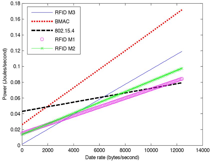
Fig. 7. Power consumption as a function of data rate for MicaZ Fig. 8. Power consumption as a function of data rate for TelosB
save up to 40% in energy consumption over MicaZ. The results RFIDImpulse-M3 has the lowest energy consumption only for
have also indicated that RFIDImpulse is more energy-efficient data rates up to 1300 bytes/second. Another notable difference
than BMAC in low traffic scenarios, and that IEEE 802.15.4 is that RFIDImpulse-M2 is the best performing protocol for
and RFIDImpulse have comparable energy performance in data rates between 1300 and 2200 bytes/second, whereas this
high traffic scenarios, thanks to the latter’s exploitation of mode is not optimal for any data with MicaZ. For data rates
traffic-based radio low power modes. The next subsection between 2200 and 10400 bytes/second, RFIDImpulse-M1 has
determines the best protocol/power mode to use for varying the lowest energy consumption, and IEEE 802.15.4 is the best
data rates with each of the node platforms. performing protocol for high data traffic.
Figures 9 and 10 summarize the recommended operation
B. Optimal Traffic Load mode/protocol for the MicaZ platform and the TelosB platform
This section uses the term data rate to express the total respectively, on the basis of data rate. For both platforms,
useful data rate, excluding all headers, footers, and preambles. RFIDImpulse-M3 is recommended for low traffic scenarios,
This is in order to compare the three protocols, which have since it yields the largest energy savings in sleep mode. For
different packet formats and preamble lengths, along the same very high data traffic, the recommendation is using IEEE
axis. However, the energy consumption does take into account 802.15.4, as the switching and backoff listening energy in
all communication overhead as well as useful data payloads. RFIDImpulse grow for higher traffic. For medium traffic
We consider a data rate between 0 bytes/second, for nodes scenarios, the results indicate that RFIDImpulse-M1 performs
that have no data to send or receive, and 12,500 bytes, which best. The exception to this rule is for data rates between 1300
corresponds to the maximum useful data rate at a level 1 node and 2200 bytes, where RFIDImpulse-M2 has the lowest energy
in the tree topology network in section IV-A. We determine the consumption. Another notable difference for the two platform
energy consumption of all protocols at each data rate through is that the threshold data rates for switching modes are
the model in section III. For RFIDImpulse, we determine the lower for TelosB relative to MicaZ. In other words, Figure 9
energy consumption at each data rate for each of the three recommends switching to RFIDImpulse-M1 for a data rate of
possible sleep modes M1, M2, and M3. 3500 bytes/second with MicaZ, whereas we would switch to
Figure 7 plots the power consumption of the protocols as M1 at 2200 bytes/second with TelosB. This difference stems
a function of data rate for the MicaZ platform. For data rates from the reduced significance of Emcu for TelosB, which
below 3500 Bytes/second, RFIDImpulse-M3 has the lowest places a higher dependence of energy consumption on data
energy consumption. For data rates between 3500 and 10500 rate, in the form of Er and Et .
bytes, RFIDImpulse-M1 exhibits the best energy performance. Because RFIDImpulse is still in the implementation pro-
For high data rates, 802.15.4 has the lowest energy consump- cess, Figures 9 and 10 also provide a head-to-head compar-
tion. These results serve as the basis for adaptive low power ison between the widely used protocols BMAC and IEEE
mode/protocol selection in software. As RFIDImpulse builds 802.15.4. For MicaZ, BMAC has lower energy consumption
on 802.15.4 radios, switching between M1, M3, and basic than IEEE 802.15.4 for data rates up to 1900 bytes/second,
802.15.4 operation can be simply implemented as a cross-layer and IEEE 802.15.4 performs better for all higher data rates.
mechanism that monitors communication traffic and decides For TelosB, BMAC performs better than IEEE 802.15.4 up to
the optimal mode through the analytical model in section III. 1400 bytes/second. The recommendation of this head-to-head
As for BMAC, it outperforms 802.15.4 for low data rates up comparison is then to consider the data traffic requirements
to 1900 bytes/second, at which point 802.15.4 performs better. for a particular sensor network application and the target node
Figure 8 plots the power consumption of the protocols as platform. If the data rate requirements for the application are
function of data rate for the TelosB platform. Although the lower than the critical threshold (1900 bytes/second for MicaZ,
energy consumption trends are similar to MicaZ, we note that 1400 bytes/second for TelosB), then BMAC should be used.9
this mode to all network nodes. A per-node implementation
demands that each node runs the model periodically and
determines its own optimal low power mode based on its traffic
load, but it also requires that nodes piggyback their current
low power mode in use unto periodic beacon messages so that
all neighbors are aware of low power modes in use in their
neighborhood [5]. In both implementations, a sender that is
aware of the low power mode in use at the receiver can send
Fig. 9. MicaZ recommended operation modes
a wake-up message and wait an appropriate length of time to
allow the receiver to power up its sleeping radio components
before commencing data transmission.
The results have also highlighted the reduction of MCU en-
ergy consumption by TelosB over MicaZ, which yields about
40% overall energy savings for networks that use TelosB. The
reduction of MCU energy consumption in TelosB also gives
prominence to the transmission and reception energy for this
platform, rendering protocol performance more sensitive to the
data traffic changes, as Figures 9 and 10 confirm. Note that the
Fig. 10. TelosB recommended operation modes
results here are also applicable to most sensor node platforms
that use ATMEL128 or MSP430 in combination with the
Otherwise, the application should use IEEE 802.15.4. CC2420 radio, such as, the Phillips Aquisgrain platform.
Cross-layer dependencies in sensor networks [15] require
consideration of not only energy performance based on the
V. D ISCUSSION choice of hardware and MAC protocols, but also the delay
This paper has provided an analytical model to conduct performance and the choice of routing and scheduling pro-
a comparative study of MAC protocol suitability of BMAC, tocols as well. An interesting direction for future work is
802.15.4, and the newly proposed RFIDImpulse across two to explore the inter-dependencies and between the choice of
popular node platforms, MicaZ and TelosB. The study has node platforms, MAC protocols, and routing and scheduling
used measured values for CC2420 radio current draw in each protocols. Keeping in mind that these dependencies exist,
of its modes for a realistic comparison of the protocols. the measurement-based comparative study in this paper will
Building on the dependence of protocol performance on hopefully serve as a guide for designers and researchers in
traffic loads, the paper has also introduced the concept of selecting node platforms and MAC protocols that are suitable
adaptive low power radio sleep modes based on the level for the expected traffic requirements in their applications.
of data traffic in the network. As a rule of thumb, deeper
sleep modes should be used for low data traffic scenarios R EFERENCES
as they have the lowest energy consumption for long sleep
[1] R. Want Enabling ubiquitous sensing with RFID, Computer journal, IEEE Com-
duration, and lighter sleep modes should be used for high puter Society, vol. 37, pp 84-86, 2004.
traffic scenarios as they provide the quicker and less costly [2] Atmel Atmega128, http://www.atmel.com.
[3] Texas Instruments cc2420 radio transceiver,
switching energy for frequent transitions between sleep and http://focus.ti.com/docs/prod/folders/print/cc2420.html.
active modes. The results in Figures 7 and 8 specify the [4] J. Polastre, J. Hill, and D. Culler, Versatile low power media access for wireless
sensor networks, (2004), 95–107.
quantitative relationship between optimal radio sleep modes [5] R. Jurdak, P. Baldi, and C.V. Lopes. “Adaptive Low Power Listening for Wireless
and data rates. Sensor Networks,”IEEE Transactions on Mobile Computing. Volume 6(8):988–
1004, August, 2007.
The comparative protocol performance analysis has shown [6] MicaZ Mote Platform. Crossbow Technologies.
that RFIDImpulse-M3 has the lowest energy consumption for [7] TelosB Mote Platform. Crossbow Technologies.
[8] A.G. Ruzzelli, G.M.P O’Hare and R. Jurdak, MERLIN: Cross-Layer Integration
low traffic scenarios for both two node platforms. Medium of MAC and Routing for Low Duty-Cycle Sensor Networks, Ad Hoc Networks
data traffic demands a switch to RFIDImpulse-M1 to maintain journal, Elsevier, February, 2008.
[9] L. Gu and J.A. Stankovic, Radio-Triggered Wake-Up Capability for Sensor
minimal energy consumption, whereas 802.15.4 performs best Networks, Proceedings of the 10th IEEE Real-Time and Embedded Technology
for high data traffic. In a head-to-head comparison between and Applications Symposium (2004).
[10] Tag Sense: RFID and Wireless Sensing http://www.tagsense.com/
BMAC and 802.15.4, BMAC performs better for low data [11] P. Skraba, Hamid Aghajan, Ahmad Bahai, RFID Wake-up in Event Driven Sensor
rates, while 802.15.4 performs better for higher data rates. Networks, Technical report, U.C. Berkeley, 2001.
[12] A.G. Ruzzelli, R. Jurdak, and G.M.P. O’Hare, On the RFID wake-up impulse
These results lay the groundwork for an enhanced IEEE for multi-hop sensor networks, In proceedings of (SenseID) Workshop at (ACM
802.15.4-compliant MAC protocol that adapts the radio low SenSys 2007), Sydney, Australia. November, 2007.
[13] A.G. Ruzzelli, P. Cotan, G.M.P. O’Hare, R.Tynan, and P.J.M Havinga, Protocol
power sleep mode in use according to observed data traffic. assessment issues in low duty cycle sensor networks: The switching energy, In
Sleep mode adaptation can be done on a network-wide or Proc. IEEE (SUTC2006), Taichung, Taiwan. June, 2006.
[14] IEEE 802.15.4 MAC/Phy standard for low-rate wireless personal area networks
per-node basis through the analytical model in Section III. In (LR-WPAN’s) http://www.ieee802.org/15/pub/TG4.html
a network-wide implementation of such a protocol, the base [15] R. Jurdak, Wireless Ad Hoc and Sensor Networks: A Cross-Layer Design
Perspecitve, Springer-Verlag, ISBN 978-0-387-39022-2, Jan., 2007.
station monitors traffic flow, determines the optimal low power
mode for the busiest node in the network, and broadcastsYou can also read