Aeronautical Chart User's Guide - Aeronautical Information Services IFR Enroute Charts - FAA
←
→
Page content transcription
If your browser does not render page correctly, please read the page content below
Federal Aviation
                                        Administration

Aeronautical Information Services

Aeronautical Chart
User’s Guide

IFR Enroute Charts

    Effective as of 13 September 2018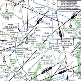
Table of Contents

WHAT’S NEW? ..................................................................................................... 5
VFR CHARTS..............................................................................................................................5
IFR ENROUTE CHARTS ............................................................................................................5
TERMINAL PROCEDURE PUBLICATIONS (TPPS)...................................................................5

INTRODUCTION ................................................................................................... 7
KEEP YOUR CHARTS CURRENT .............................................................................................7
EFFECTIVE DATE OF CHART USER’S GUIDE AND UPDATES ..............................................7
COLOR VARIATION ....................................................................................................................7
REPORTING CHART DISCREPANCIES ....................................................................................7

EXPLANATION OF IFR ENROUTE TERMS ........................................................ 9
AIRPORTS ..................................................................................................................................9
RADIO AIDS TO NAVIGATION ................................................................................................. 11
AIRSPACE INFORMATION .......................................................................................................12
INSTRUMENT AIRWAYS ..........................................................................................................14
TERRAIN CONTOURS ON AREA CHARTS .............................................................................17

                                                                                                                                                        FAA Chart User’s Guide - Table of Contents
AIRPORTS ................................................................................................................................19

IFR ENROUTE LOW / HIGH ALTITUDE SYMBOLS (U.S., PACIFIC AND ALASKA
CHARTS) ............................................................................................................ 19
RADIO AIDS TO NAVIGATION .................................................................................................20
AIRSPACE INFORMATION .......................................................................................................25
NAVIGATIONAL AND PROCEDURAL INFORMATION ............................................................38
CULTURE ..................................................................................................................................39
HYDROGRAPHY ......................................................................................................................39
TOPOGRAPHY .........................................................................................................................39

REFERENCES .................................................................................................... 41

ABBREVIATIONS ............................................................................................... 43
A ................................................................................................................................................43
B ................................................................................................................................................43
C ................................................................................................................................................43
D ................................................................................................................................................43
E ................................................................................................................................................43
F ................................................................................................................................................43
G ................................................................................................................................................43
H ................................................................................................................................................43
I..................................................................................................................................................43
K ................................................................................................................................................44
L.................................................................................................................................................44
M................................................................................................................................................44
N ................................................................................................................................................44
O ................................................................................................................................................44

                                                                              3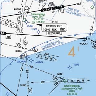
Table of Contents
                                             P ................................................................................................................................................44
                                             R ................................................................................................................................................44
                                             S ................................................................................................................................................44
                                             T ................................................................................................................................................45
                                             U ................................................................................................................................................45
                                             V ................................................................................................................................................45
                                             W ...............................................................................................................................................45
FAA Chart User’s Guide - Table of Contents

                                                                                                                           4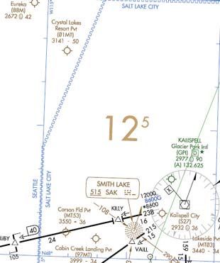
WHAT’S NEW?
                                               Update as of 13 September 2018

The following charting items have been added to the Online Chart User’s Guide since the Guide was last published on 29 March 2018:

VFR CHARTS

No Changes Applied

IFR ENROUTE CHARTS

ENROUTE CONTROLLER PILOT DATA LINK COMMUNICATIONS (CPDLC)

Enroute Controller Pilot Data Link Communication (CPDLC) is a system that supplements air/ground voice communications. The an-
notation of KUSA refers to the CPDLC current data authority that is indicated on the applicable flight deck display to confirm to the flight
crew that a CPDLC connection has been established.

Enroute CPDLC services will be implemented one Air Route Traffic Control
Center (ARTCC) at a time beginning in the fall of 2018 and concluding in the
fall of 2019. The first three facilities scheduled to conduct CPDLC operations
are Indianapolis ARTCC, Kansas City ARTCC, and Memphis ARTCC.

Additional guidance can be found in the Aeronautical Information Manual
(AIM) paragraph 5-3-1.

                                                                                                                                               FAA Chart User’s Guide - What’s New
TERMINAL PROCEDURE PUBLICATIONS (TPPS)

HELICOPTER (COPTER) CHART RELATED UPDATES

New Copter Approach and Departure charting specifications were added for the depictions of VFR versus Visual Seg-
ments. Copter procedures with a Visual Segment will depict the visual flight path with the dashed line symbol below. Exist-
ing Copter Procedure charts will be updated on a day forward basis.

                                                             Visual Segment

VFR Segments will not be depicted with a line, but will include the reference bearing and distance information at the end-
point of the VFR Segment, when provided, as shown below.

       Copter Approach                                                                          Copter Departure

                                                                     5
FAA Chart User’s Guide - What’s New

6

INTRODUCTION
This Chart User's Guide is an introduction to the Federal Aviation Administration's (FAA) aeronautical charts and publica-
tions. It is useful to new pilots as a learning aid, and to experienced pilots as a quick reference guide.

The FAA is the source for all data and information utilized in the publishing of aeronautical charts through authorized
publishers for each stage of Visual Flight Rules (VFR) and Instrument Flight Rules (IFR) air navigation including training,
planning, and departures, enroute (for low and high altitudes), approaches, and taxiing charts. Digital charts are available
online at:

     •   VFR Charts - https://www.faa.gov/air_traffic/flight_info/aeronav/digital_products/vfr/
     •   IFR Charts - https://www.faa.gov/air_traffic/flight_info/aeronav/digital_products/ifr/
     •   Terminal Procedures Publication - http://www.faa.gov/air_traffic/flight_info/aeronav/digital_products/dtpp/
     •   Chart Supplements - https://www.faa.gov/air_traffic/flight_info/aeronav/digital_products/dafd/

Paper copies of the charts are available through an FAA Approved Print Provider. A complete list of current providers is
available at http://www.faa.gov/air_traffic/flight_info/aeronav/print_providers/

The FAA Aeronautical Information Manual (AIM) Pilot/Controller Glossary defines in detail, all terms and abbreviations
used throughout this publication. Unless otherwise indicated, miles are nautical miles (NM), altitudes indicate feet above
Mean Sea Level (MSL), and times used are Coordinated Universal Time (UTC).

The Notices to Airmen Publication (NOTAM) includes current Flight Data Center (FDC) NOTAMs. NOTAMs alert pilots of
new regulatory requirements and reflect changes to Standard Instrument Approach Procedures (SIAPs), flight restrictions,

                                                                                                                                      FAA Chart User’s Guide - Introduction
and aeronautical chart revisions. This publication is prepared every 28 days by the FAA, and is available by subscription
from the Government Printing Office. For more information on subscribing or to access online PDF copy, http://www.faa.
gov/air_traffic/publications/notices/

In addition to NOTAMs, the Chart Supplement and the Safety Alerts/Charting Notices page of the Aeronautical Information
Services website are also useful to pilots

KEEP YOUR CHARTS CURRENT                                            COLOR VARIATION

Aeronautical information changes rapidly, so it is impor-           Although the digital files are compiled in accordance with
tant that pilots check the effective dates on each aeronau-         charting specifications, the final product may vary slightly in
tical chart and publication. To avoid danger, it is important       appearance due to differences in printing techniques/pro-
to always use current editions and discard obsolete                 cesses and/or digital display techniques.
charts and publications.
                                                                    REPORTING CHART DISCREPANCIES
To confirm that a chart or publication is current, refer to
the next scheduled edition date printed on the cover.               Your experience as a pilot is valuable and your feedback is
Pilots should also check Aeronautical Chart Bulletins and           important. We make every effort to display accurate informa-
NOTAMs for important updates between chart and publi-               tion on all FAA charts and publications, so we appreciate
cation cycles that are essential for safe flight.                   your input. Please notify us concerning any requests for
                                                                    changes, or potential discrepancies you see while using our
EFFECTIVE DATE OF CHART USER’S GUIDE                                charts and related products.
AND UPDATES
                                                                              FAA, Aeronautical Information Services
All information in this guide is effective as of 13 Septem-                   Customer Operations Team
ber 2018. All graphics used in this guide are for educa-                      1305 East-West Highway
tional purposes. Chart symbology may not be to scale.                         SSMC4 Suite 4400
Please do not use them for flight navigation.                                 Silver Spring, MD 20910-3281

The Chart User’s Guide is updated as necessary when                           Telephone Toll-Free 1-800-638-8972
there is new chart symbology or changes in the depiction                      E-mail: 9-AMC-Aerochart@faa.gov
of information and/or symbols on the charts. When there
are changes, it will be in accordance with the 56-day
aeronautical chart product schedule.

                                                                7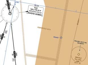
FAA Chart User’s Guide - Introduction

8
EXPLANATION OF IFR ENROUTE TERMS
FAA charts are prepared in accordance with specifications of the Interagency Air Committee (IAC), and are approved by
representatives of the Federal Aviation Administration and the Department of Defense (DoD). Some information on these
charts may only apply to military pilots.

The explanations of symbols used on Instrument Flight Rule (IFR) Enroute Charts and examples in this section are based
primarily on the IFR Enroute Low Altitude Charts. Other IFR products use similar symbols in various colors. The chart leg-
ends portray aeronautical symbols with a brief description of what each symbol depicts. This section provides more details
of the symbols and how they are used on IFR Enroute charts.

AIRPORTS

Active airports are shown on IFR Enroute Charts.

Low Charts:

     •   All IAP Airports are shown on the Low Altitude Charts (US and Alaska).

     •   Non-IAP Airports are shown on the U.S. Low Altitude Charts (Contiguous US) have a minimum hard surface
         runway of 3,000’.

     •   Non-IAP airports are shown on the U.S. Low Altitude Alaska Charts are show if the runway is 3000’ or longer,

                                                                                                                                FAA Chart User’s Guide - IFR Enroute Terms
         hard or soft surface.

     •   Public heliports with an Instrument Approach Procedure (IAP) or requested by the FAA or DoD are depicted on
         the IFR Enroute Low Altitude Charts.

     •   Seaplane bases requested by the FAA or DoD are depicted on the IFR Enroute Low Altitude Charts.

On IFR Enroute Low Altitude Charts, airport tabulation is provided which identifies airport names, IDs and the panels they
are located on.

High Charts:

     •   Airports shown on the U.S. High Enroute Charts (Contiguous US) have a minimum hard surface runway of 5000’.

     •   Airports shown on the U.S. High Enroute Alaska Charts have a minimum hard surface runway of 4000’.

Charted airports are classified according to the following criteria:

                                                    LOW/HIGH ALTITUDE

         Blue - Airports with an Instrument Approach Procedure and/or RADAR MINIMA published in the high altitude DoD
         Flight Information Publications (FLIPs)

         Green - Airports which have an approved Instrument Approach Procedure and/or RADAR MINIMA published in
         either the U.S. Terminal Procedures Publications (TPPs) or the DoD FLIPs

         Brown - Airports without a published Instrument Approach Procedure or RADAR MINIMA

Airports are plotted at their true geographic position.

Airports are identified by the airport name. In the case of military airports, Air Force Base (AFB), Naval Air Station (NAS),
Naval Air Facility (NAF), Marine Corps Air Station (MCAS), Army Air Field (AAF), etc., the abbreviated letters appear as
part of the airport name.

                                                               9
Airports marked "Pvt" immediately following the airport name are not for public use, but otherwise meet the criteria for
charting as specified above.
Runway length is the length of the longest active runway (including displaced thresholds but excluding overruns) and is
shown to the nearest 100 feet using 70 feet as the division point; e.g., a runway of 8,070' is labeled 81. The following run-
way compositions (materials) constitute a hard-surfaced runway: asphalt, bitumen, chip seal, concrete, and tar macadam.
Runways that are not hard-surfaced have a small letter "s" following the runway length, indicating a soft surface.
AIRPORT DATA DEPICTION
Low Altitude
1. Airport elevation given in feet above or below mean sea level 6. Associated city names for public airports are shown above or
preceding the airport name. If airport name and city name are
2. Pvt - Private use, not available to general public the same, only the airport name is shown. The airport identifier in
parentheses follows the airport name. City names for military and
3. A solid line box enclosed the airport name indicates FAR 93 private airports are not shown.
Special Requirements - see Directory/Supplement
7. Airport Ident ICAO Location Indicator shown outside contigu-
4. “NO SVFR” above the airport name indicates FAR 91 fixed- ous U.S.
wing special VFR flight is prohibited.
FAA Chart User’s Guide - IFR Enroute Terms
8. AFIS Alaska only
5. or following the airport identifier indicates Class C or
Class D Airspace
High Altitude - U.S. High Altitude - Alaska
LIGHTING CAPABILITY
Lighting Available Part-time or on request
Pilot Controlled Airport No lighting available
At private facilities- indicates no lighting
information is available
A symbol between the airport elevation and runway length means that runway lights are in operation sunset to sunrise.
A symbol indicates there is Pilot Controlled Lighting. A symbol means the lighting is part-time or on request, the
pilot should consult the Chart Supplement for light operating procedures. The Aeronautical Information Manual (AIM) thor-
oughly explains the types and uses of airport lighting aids.
10RADIO AIDS TO NAVIGATION
All IFR radio NAVAIDs that have been flight checked and are operational are shown on all IFR Enroute Charts. Very High
Frequency/Ultrahigh Frequency (VHF/UHF) NAVAIDs, Very high frequency Omnidirectional Radio range (VORs), Tactical
Air Navigation (TACANs) are shown in black, and Low Frequency/Medium Frequency (LF/MF) NAVAIDs, (Compass Loca-
tors and Aeronautical or Marine NDBs) are shown in brown.
On IFR Enroute Charts, information about NAVAIDs is boxed as illustrated below. To avoid duplication of data, when two
or more NAVAIDs in a general area have the same name, the name is usually printed only once inside an identification
box with the frequencies, TACAN channel numbers, identification letters, or Morse Code Identifications of the different
NAVAIDs are shown in appropriate colors.
NAVAIDs in a shutdown status have the frequency and channel number crosshatched. Use of the NAVAID status "shut-
down" is only used when a facility has been decommissioned but cannot be published as such because of pending
airspace actions.
NAVIGATION AND COMMUNICATION BOXES - COMMON ELEMENTS
LOW ENROUTE CHARTS HIGH ENROUTE CHARTS
RCO Frequencies RCO Frequencies
NAVAID Name NAVAID Name
FREQ, Ident, CH, Morse Code Frequency, Ident, Channel,
Latitude, Longitude Latitude, Longitude
Controlling FSS Name
FAA Chart User’s Guide - IFR Enroute Terms
Controlling FSS Name
COMMON ELEMENTS (HIGH AND LOW CHARTS)
RCO FREQUENCY
Single Frequency
Multiple Frequencies
Frequencies transmit and receive except those followed by R and
T:
R - Receive Only T - Transmit Only
NAVAID BOX VHF/UHF LF/MF
Thin line NAVAID boxes without frequency(s) and FSS radio
name indicates no FSS frequencies available.
Shadow NAVAID box indicates NAVAID and Flight Service Sta-
tion (FSS) have same name.
FREQUENCY PROTECTION
Frequency Protection usable range at 18,000’ AGL - 40 NM (L)
Frequency Protection usable range at 12,000’ AGL - 25 NM (T)
DISTANCE MEASURING EQUIPMENT
Facilities that operate in the “Y” mode for DME reception (Y)
VOICE COMMUNICATIONS VIA NAVAID
Voice Transmitted
No Voice Transmitted
NAVAID SHUTDOWN STATUS VHF/UHF LF/MF
PART TIME OR ON-REQUEST VHF/UHF LF/MF
11AUTOMATED WEATHER BROADCAST SERVICES VHF/UHF LF/MF
ASOS/AWOS - Automated Surface Observing Station/Automated
Weather Observing Station
HIWAS - Hazardous Inflight Weather Advisory Service
TWEB - Transcribed Weather Broadcast
Automated weather, when available, is broadcast on the associ-
ated NAVAID frequency.
LATITUDE AND LONGITUDE LOW ENROUTE HIGH ENROUTE
Latitude and Longitude coordinates are provided for those
NAVAIDs that make up part of a route/airway or a holding pattern.
All TACAN facilities will include geographic coordinates.
AIRSPACE INFORMATION
CONTROLLED AIRSPACE
Controlled airspace consists of those areas where some or all aircraft are subjected to air traffic control within the follow-
ing airspace classifications of A, B, C, D, & E.
FAA Chart User’s Guide - IFR Enroute Terms
Air Route Traffic Control Centers (ARTCC) are established to provide Air Traffic Control to aircraft operating on IFR flight
plans within controlled airspace, particularly during the enroute phase of flight. Boundaries of the ARTCCs are shown in
their entirety using the symbol below.
Air Route Traffic Control Center (ARTCC)
When Controller Pilot Data Link Communication (CPDLC) exists for an ARTCC, the text CPDLC (LOGON KUSA) will be
shown parallel to the boundary above or below the ARTCC identification as shown below.
Air Route Traffic Control Center (ARTCC) with
Controller Pilot Data Link Communication (CPDLC)
The responsible ARTCC Center names are shown adjacent and parallel to the boundary line. ARTCC sector frequencies
are shown in boxes outlined by the same symbol.
ARTCC Name ARTCC Remoted Sites with
Site Name
Frequency discrete VHF and UHF frequencies
Class A Airspace is depicted as open area (white) on the IFR Enroute High Altitude Charts. It consists of
airspace from 18,000 Mean Sea Level (MSL) to FL600.
Class B Airspace is depicted as screened blue area with a solid line encompassing the area.
Class C Airspace is depicted as screened blue area with a dashed line encompassing the area with a
following the airport name.
Class B and Class C Airspace consist of controlled airspace extending upward from the surface or a
designated floor to specified altitudes, within which all aircraft and pilots are subject to the operating
rules and requirements specified in the Federal Aviation Regulations (UHF) 71. Class B and C Airspace
are shown in abbreviated forms on IFR Enroute Low Altitude Charts. A general note adjacent to Class B
airspace refers the user to the appropriate VFR Terminal Area Chart.
12Class D Airspace (airports with an operating control tower) are depicted as open area (white) with a fol-
lowing the airport name.
Class E Airspace is depicted as open area (white) on the IFR Enroute Low Altitude Charts. It consists of
airspace below FL180.
UNCONTROLLED AIRSPACE
Class G Airspace within the United States extends to 14,500’ MSL. This uncontrolled airspace is shown
as screened brown.
On Area Charts any uncontrolled airspace boundaries are depicted with a .012” brown line and a .060”
screen brown band on the uncontrolled side, so as to be seen over the terrain.
SPECIAL USE AIRSPACE
Special Use Airspace (SUA) confines certain flight activities, restricts entry, or cautions other aircraft operating within
specific boundaries. SUA areas are shown in their entirety, even when they overlap, adjoin, or when an area is designated
within another area. SUA with altitudes from the surface and above are shown on the IFR Enroute Low Altitude Charts.
Similarly, SUA that extends above 18,000' MSL are shown on IFR Enroute High Altitude Charts. On IFR Enroute Altitude
Charts tabulations, identify the type of SUA, ID, effective altitudes, times of use, controlling agency and the panel it is
located on.
FAA Chart User’s Guide - IFR Enroute Terms
High and Low Low Altitude Only Canada Only Caribbean Only
P - Prohibited Area MOA - Military Operations Area CYA - Advisory D - Danger
R - Restricted Area A - Alert Area CYD - Danger Area
W - Warning Area CYR - Restricted Area
See Airspace Tabulation on chart for complete information.
OTHER AIRSPACE
FAR 91 Special Air Traffic Rules are shown with the type NO SVFR above the airport name.
FAR 93 Special Airspace Traffic Rules are shown with a solid line box around the airport name, indicating FAR 93 Spe-
cial Requirements see Chart Supplement.
13Mode C Required Airspace (from the surface to 10,000' MSL) within 30 NM radius of the primary airport(s) for which a
Class B airspace is designated, is depicted on IFR Enroute Low Altitude Charts as a blue circle labeled MODE C 30 NM.
Mode C is also required for operations within and above all Class C airspace up to 10,000' MSL, but not depicted. See
FAR 91.215 and the AIM.
INSTRUMENT AIRWAYS
The FAA has established two fixed route systems for air navigation. The VOR and LF/MF system-designated from 1,200'
Above Ground Level (AGL) to but not including FL 180 is shown on IFR Enroute Low Altitude Charts, and the Jet Route
system designated from FL 180 to FL 450 inclusive is shown on IFR Enroute High Altitude Charts.
VOR LF/MF AIRWAY SYSTEM (IFR LOW ALTITUDE ENROUTE CHARTS)
In this system VOR airways - airways based on VOR or VORTAC NAVAIDs - are depicted in black and identified by a "V"
(Victor) followed by the route number (e.g., "V12").
LF/MF airways - airways based on LF/MF NAVAIDs - are sometimes called "colored airways" because they are identified
by color name and number (e.g., "Amber One", charted as "A1"). In Alaska Green and Red airways are plotted east and
west, and Amber and Blue airways are plotted north and south. Regardless of their color identifier, LF/MF airways are
shown in brown.
FAA Chart User’s Guide - IFR Enroute Terms
AIRWAY/ROUTE DATA
On both series of IFR Enroute Charts, airway/route data such as the airway identifications, magnetic courses bearings or
radials, mileages, and altitudes (e.g., Minimum Enroute Altitudes (MEAs), Minimum Reception Altitudes (MRAs), Maxi-
mum Authorized Altitudes (MAAs), Minimum Obstacle Clearance Altitudes (MOCAs), Minimum Turning Altitudes (MTAs)
and Minimum Crossing Altitudes (MCAs)) are shown aligned with the airway.
As a rule the airway/route data is charted and in the same color as the airway, with one exception. Charted in blue, Global
Navigation Satellite System (GNSS) MEAs, identified with a "G" suffix, have been added to "V" and "colored airways" for
aircraft flying those airways using Global Positioning System (GPS) navigation.
Airways/Routes predicated on VOR or VORTAC NAVAIDs are defined by the outbound radial from the NAVAID. Airways/
Routes predicated on LF/MF NAVAIDs are defined by the inbound bearing.
• Minimum Enroute Altitude (MEA) - The MEA is the lowest published altitude between radio fixes that assures
acceptable navigational signal coverage and meets obstacle clearance requirements between those fixes. The
MEA prescribed for a Federal airway or segment, RNAV low or high route, or other direct route applies to the en-
tire width of the airway, segment, or route between the radio fixes defining the airway, segment, or route. MEAs for
routes wholly contained within controlled airspace normally provide a buffer above the floor of controlled airspace
consisting of at least 300 feet within transition areas and 500 feet within control areas. MEAs are established
based upon obstacle clearance over terrain and manmade objects, adequacy of navigation facility performance,
and communications requirements.
• Minimum Reception Altitude (MRA) - MRAs are determined by FAA flight inspection traversing an entire route
of flight to establish the minimum altitude the navigation signal can be received for the route and for off-course
NAVAID facilities that determine a fix. When the MRA at the fix is higher than the MEA, an MRA is established for
the fix and is the lowest altitude at which an intersection can be determined.
• Maximum Authorized Altitude (MAA) - An MAA is a published altitude representing the maximum usable
altitude or flight level for an airspace structure or route segment. It is the highest altitude on a Federal airway, jet
route, RNAV low or high route, or other direct route for which an MEA is designated at which adequate reception
of navigation signals is assured.
14• Minimum Obstruction Clearance Altitude (MOCA) - The MOCA is the lowest published altitude in effect be-
tween fixes on VOR airways, off-airway routes, or route segments that meets obstacle clearance requirements for
a VOR. The MOCA seen on the enroute chart may have been computed by adding the required obstacle clear-
ance (ROC) to the controlling obstacle in the primary area or computed by using a TERPS chart if the control-
ling obstacle is located in the secondary area. This figure is then rounded to the nearest 100 foot increment (i.e.,
2,049 feet becomes 2,000, and 2,050 feet becomes 2,100 feet). An extra 1,000 feet is added in mountainous
areas, in most cases.
• Minimum Turning Altitude (MTA) - Minimum turning altitude (MTA) is a charted altitude providing vertical and
lateral obstruction clearance based on turn criteria over certain fixes, NAVAIDs, waypoints, and on charted route
segments. When a VHF airway or route terminates at a NAVAID or fix, the primary area extends beyond that
termination point. When a change of course on VHF airways and routes is necessary, the enroute obstacle clear-
ance turning area extends the primary and secondary obstacle clearance areas to accommodate the turn radius
of the aircraft. Since turns at or after fix passage may exceed airway and route boundaries, pilots are expected to
adhere to airway and route protected airspace by leading turns early before a fix. The turn area provides obstacle
clearance for both turn anticipation (turning prior to the fix) and flyover protection (turning after crossing the fix).
Turning fixes requiring a higher MTA are charted with a flag along with accompanying text describing the MTA
restriction.
• Minimum Crossing Altitude (MCA) - An MCA is the lowest altitude at certain fixes at which the aircraft must
cross when proceeding in the direction of a higher minimum enroute IFR altitude. MCAs are established in all
cases where obstacles intervene to prevent pilots from maintaining obstacle clearance during a normal climb to a
higher MEA after passing a point beyond which the higher MEA applies. The same protected enroute area vertical
obstacle clearance requirements for the primary and secondary areas are considered in the determination of the
FAA Chart User’s Guide - IFR Enroute Terms
MCA.
Victor Route (with RNAV/GPS MEA shown in blue)
AREA NAVIGATION (RNAV) "T" ROUTE SYSTEM
The FAA has created new low altitude area navigation (RNAV) "T" routes for the enroute and terminal environments. The
RNAV routes will provide more direct routing for IFR aircraft and enhance the safety and efficiency of the National Air-
space System. To utilize these routes aircraft are required to be equipped with IFR approved GNSS. In Alaska, TSO-145a
and 146a equipment is required.
Low altitude RNAV only routes are identified by the prefix "T", and the prefix "TK" for RNAV helicopter routes followed by a
three digit number (T-200 to T-500). Routes are depicted in blue on the IFR Enroute Low Altitude Charts. RNAV route data
(route line, identification boxes, mileages, waypoints, waypoint names, magnetic reference courses and MEAs) will also
be printed in blue. Magnetic reference courses will be shown originating from a waypoint, fix/reporting point or NAVAID.
GNSS MEA for each segment is established to ensure obstacle clearance and communications reception. GNSS MEAs
are identified with a "G" suffix.
15Joint Victor/RNAV routes are charted as outlined above except as noted. The joint Victor route and the RNAV route iden-
tification boxes are shown adjacent to each other. Magnetic reference courses are not shown. MEAs are charted above
the appropriate identification box or stacked in pairs, GNSS and Victor. On joint routes, RNAV specific information will be
printed in blue.
OFF ROUTE OBSTRUCTION CLEARANCE ALTITUDE (OROCA)
The Off Route Obstruction Clearance Altitude (OROCA) is depicted on IFR Enroute Low Altitude and Pacific charts and
is represented in thousands and hundreds of feet above MSL. OROCAs are shown in every 30 x 30 minute quadrant on
Area Charts, every one degree by one degree quadrant for IFR Enroute Low Altitude Charts - U.S. and every two de-
gree by two degree quadrant on IFR Enroute Low Altitude Charts - Alaska. The OROCA represents the highest possible
obstruction elevation including both terrain and other vertical obstruction data (towers, trees, etc.) bounded by the ticked
FAA Chart User’s Guide - IFR Enroute Terms
lines of latitude/longitude including data 4 NM outside the quadrant. In this example the OROCA represents 12,500 feet.
OROCA is computed just as the Maximum Elevation Figure (MEF) found on Visual Flight Rule (VFR) Charts except that
it provides an additional vertical buffer of 1,000 feet in designated non-mountainous areas and a 2,000 foot vertical buffer
in designated mountainous areas within the United States. For areas in Mexico and the Caribbean, located outside the
U.S. Air Defense Identification Zone (ADIZ), the OROCA provides obstruction clearance with a 3,000 foot vertical buffer.
Evaluating the area around the quadrant provides the chart user the same lateral clearance an airway provides should
the line of intended flight follow a ticked line of latitude or longitude. OROCA does not provide for NAVAID signal cover-
age, communication coverage and would not be consistent with altitudes assigned by Air Traffic Control. OROCAs can be
found over all land masses and open water areas containing man-made obstructions (such as oil rigs).
MILITARY TRAINING ROUTES (MTRs)
Military Training Routes (MTRs) are routes established for the conduct of low-altitude, high-speed military flight training
(generally below 10,000 feet MSL at airspeeds in excess of 250 knots Indicated Air Speed). These routes are depicted in
brown on IFR Enroute Low Altitude Charts, and are not shown on inset charts or on IFR Enroute High Altitude Charts. IFR
Enroute Low Altitude Charts depict all IFR Military Training Routes (IRs) and VFR Military Training Routes (VRs), except
those VRs that are entirely at or below 1,500 feet AGL.
MTRs are identified by designators (IR-107, VR-134) which are shown in brown on the route centerline. Arrows are shown
to indicate the direction of flight along the route. The width of the route determines the width of the line that is plotted on
the chart:
Route segments with a width of 5 NM or less, both sides of the centerline, are shown by a .02" line.
Route segments with a width greater than 5 NM, either or both sides of the centerline, are shown by a .035" line.
MTRs for particular chart pairs (ex. L1/2, etc.) are alphabetically, then numerically tabulated. The tabulation includes MTR
type and unique identification and altitude range.
16JET ROUTE SYSTEM (HIGH ALTITUDE ENROUTE CHARTS)
Jet routes are based on VOR or VORTAC NAVAIDs, and are depicted in black with a "J" identifier followed by the route
number (e.g., "J12"). In Alaska, Russia and Canada some segments of jet routes are based on LF/MF NAVAIDs.
AREA NAVIGATION (RNAV) "Q" ROUTE SYSTEM (IFR Enroute HIGH ALTITUDE CHARTS)
The FAA has adopted certain amendments to Title 14, Code of Federal Regulations which paved the way for the develop-
ment of new area high altitude navigation (RNAV) "Q" routes in the U.S. National Airspace System (NAS). These amend-
ments enable the FAA to take advantage of technological advancements in navigation systems such as the GPS. RNAV
"Q" Route MEAs are shown when other than FL 180 MEAs for DME/DME/Inertial Reference Unit (IRU) RNAV aircraft
have a "D" suffix.
RNAV routes and associated data are charted in blue.
"Q" Routes on the IFR Gulf of Mexico charts are shown in black. Magnetic reference courses are shown originating from a
waypoint, fix/reporting point, or NAVAID.
Joint Jet/RNAV route identification boxes will be located adjacent to each other with the route charted in black. With the
exception of Q-Routes in the Gulf of Mexico, GNSS or DME/DME/IRU RNAV are required, unless otherwise indicated.
DME/DME/IRU RNAV aircraft should refer to the Chart Supplement for DME information. Q-Routes in Alaska are GNSS
FAA Chart User’s Guide - IFR Enroute Terms
Only. Altitude values are stacked highest to lowest.
TERRAIN CONTOURS ON AREA CHARTS
Based on a recommendation of the National Transportation Safety Board, terrain contours have been added to the
Enroute Area Charts and are intended to increase pilots' situational awareness for safe flight over changes in terrain. The
following Area Charts portray terrain: Anchorage, Denver, Fairbanks, Juneau, Los Angeles, Nome, Phoenix, San Fran-
cisco, Vancouver and Washington.
When terrain rises at least a 1,000 feet above the primary airports' elevation, terrain is charted using shades of brown with
brown contour lines and values. The initial contour will be 1,000 or 2,000 feet above the airports' elevation. Subsequent
intervals will be 2,000 or 3,000 foot increments.
Contours are supplemented with a representative number of spots elevations and are shown in solid black. The highest
elevation on an Area Chart is shown with a larger spot and text.
The following boxed note is added to the affected Area Charts.
17FAA Chart User’s Guide - IFR Enroute Terms 18
IFR ENROUTE LOW / HIGH ALTITUDE SYMBOLS
                      (U.S., PACIFIC AND ALASKA CHARTS)
AIRPORTS

Airport Data - Low/High Altitude
Civil                          Charts: High/Low                          Seaplane - Civil                     Charts: Low

Civil And Military                    Charts: High/Low                   Heliport                             Charts: Low

Military                              Charts: High/Low                   Emergency Use Only
                                                                                                                  Pacific Only

Facilities in BLUE or GREEN have an approved Instrument Approach Procedure and/or RADAR MINIMA published in either the FAA
Terminal Procedures Publication or the DoD FLIPs. Those in BLUE have an Instrument Approach Procedure and/or RADAR MINIMA
published at least in the High Altitude DoD FLIPs. Facilities in BROWN do not have a published Instrument Procedure or RADAR
MINIMA.

All IAP Airports are shown on the Low Altitude Charts.

                                                                                                                                               FAA Chart User’s Guide - IFR Enroute Symbology
Non-IAP Airports shown on the U.S. Low Altitude Charts have a minimum hard surface runway of 3000’.

Airports shown on the U.S. High Altitude Charts have a minimum hard surface runway of 5000’.

Airports shown on the Alask High Altitude Charts have a minimum hard or soft surface runway of 4000’.

Associated city names for public airports are shown above or preceding the airport name and city name are the same only the airport
name is shown. City names for military and private airports are not shown.

The airport identifier in parentheses follows the airport name or Pvt.

Pvt - Private Use
AIRPORT DATA DEPICTION

Low Altitude

1. Airport elevation given in feet above or below mean sea level         6. Associated city names for public airports are shown above or
                                                                         preceding the airport name. If airport name and city name are
2. Pvt - Private use, not available to general public                    the same, only the airport name is shown. The airport identifier in
                                                                         parentheses follows the airport name. City names for military and
3. A solid line box enclosed the airport name indicates FAR 93           private airports are not shown.
Special Requirements - see Directory/Supplement
                                                                         7. Airport Ident ICAO Location Indicator shown outside contiguous
4. “NO SVFR” above the airport name indicates FAR 91 fixed-              U.S.
wing special VFR flight is prohibited.
                                                                         8. AFIS Alaska only
5.    or    following the airport identifier indicates Class C or
Class D Airspace                                                         High Altitude - Alaska

High Altitude - U.S.

                                                                    19
Airports (Continued)
LIGHTING CAPABILITY
Lighting Available Part-time or on request
Pilot Controlled Airport No lighting available
At private facilities- indicates no lighting
information is available
RADIO AIDS TO NAVIGATION
NAVAIDS
VOR VOR/DME TACAN DME NDB NDB/DME Reporting Function
Non Compulsory Reporting or Off Airway
Compulsory Reporting
Note: VHF/UHF is depicted in Black. LF/MF is depicted in Brown. RNAV is depicted in Blue
Compass Roses
FAA Chart User’s Guide - IFR Enroute Symbology
VHF/UHF LF/MF
Compass Roses are orientated to Magnetic North of the NAVAID which may not be adjusted to the charted isogonic values.
Compass Locator Beacon
LOW ALTITUDE Chart Example : Enroute Low L-16 US
20RADIO AIDS TO NAVIGATION (Continued)
LOW ALTITUDE ILS Localizer Example with Back Course
ILS LOCALIZER (Chart: Enroute Low L-1 US)
ILS Localizer Course with
additional navigation function
ILS Localizer Back Course with
additional navigation function
HIGH ALTITUDE - ALASKA
VOR/DME RNAV
WAYPOINT DATA
Coordinates
Frequency Radial/Distance
(Facility to Waypoint)
Identifier Reference
Facility Elevation
FAA Chart User’s Guide - IFR Enroute Symbology
NAVIGATION AND COMMUNICATION BOXES - COMMON ELEMENTS
LOW ENROUTE CHARTS HIGH ENROUTE CHARTS
RCO Frequencies RCO Frequencies
NAVAID Name NAVAID Name
FREQ, Ident, CH, Morse Code Frequency, Ident, Channel,
Latitude, Longitude Latitude, Longitude
Controlling FSS Name
Controlling FSS Name
COMMON ELEMENTS (HIGH AND LOW CHARTS)
RCO Frequency
Single Frequency
Multiple Frequencies
Frequencies transmit and receive except those followed by R
and T:
R - Receive Only T - Transmit Only
NAVAID Box
VHF/UHF LF/MF
Thin line NAVAID boxes without frequency(s) and FSS radio name
indicates no FSS frequencies available.
Shadow NAVAID box indicates NAVAID and Flight Service Station
(FSS) have same name.
21RADIO AIDS TO NAVIGATION (Continued)
Navigation and Communication Boxes - Common Elements
Frequency Protection
(L)
Frequency Protection usable range at 18,000’ AGL - 40 NM
(T)
Frequency Protection usable range at 12,000’ AGL - 25 NM
DISTANCE MEASURING EQUIPMENT
(Y)
Facilities that operate in the “Y” mode for DME reception
VOICE COMMUNICATIONS VIA NAVAID
Voice Transmitted
No Voice Transmitted
VHF/UHF LF/MF
NAVAID SHUTDOWN STATUS
FAA Chart User’s Guide - IFR Enroute Symbology
VHF/UHF LF/MF
PART TIME OR ON-REQUEST
AUTOMATED WEATHER BROADCAST SERVICES
VHF/UHF LF/MF
ASOS/AWOS - Automated Surface Observing Station/Automated
Weather Observing Station
HIWAS - Hazardous Inflight Weather Advisory Service
TWEB - Transcribed Weather Broadcast
LATITUDE AND LONGITUDE
Latitude and Longitude coordinates are provided for those
LOW ENROUTE HIGH ENROUTE
NAVAIDs that make up part of a route/airway or a holding pattern.
All TACAN facilities will include geographic coordinates.
Navigation and Communication Boxes - Examples
LOW ENROUTE CHARTS HIGH ENROUTE CHARTS
VOR VOR
R - Receive only 122.1R
Controlling FSS Name - ANDERSON
(T) - Service Volume
Receive & Transmit on 122.35
(T) - Service Volume
Latitude and Longitude
Controlling FSS Name - MACON
22RADIO AIDS TO NAVIGATION (Continued)
Navigation And Communication Boxes - Examples (Continued)
LOW ENROUTE CHARTS HIGH ENROUTE CHARTS
VOR/DME VOR/DME
No Voice Communications Off Route (Greyed NAVAID Box
(Y) Mode DME and NAVAID)
R - Receive only 122.1R Service Volume - L
Controlling FSS Name - BUFFALO DME in Y Mode
Shadow NAVAID Box Shadow NAVAID Box
FSS Associated with NAVAID FSS Associated with NAVAID
TACAN TACAN
TACAN Channels are without Off Route
voice but not underlined
Off Route - Part Time NAVAID
Part Time NAVAID (Greyed NAVAID Box and NAVAID)
Service Volume - L
FAA Chart User’s Guide - IFR Enroute Symbology
VORTAC VORTAC
H - HIWAS Available H - HIWAS Available
Shutdown status Off Route (Greyed NAVAID Box
and NAVAID)
Service Volume - L
DME DME
DME Channel, Ident, Morse Code,
VHF Frequency
NDB NDB
A - ASOS/AWOS Available T - TWEB Available
Shutdown status
NDB/DME NDB/DME
No Voice Communications No Voice Communications
(Y) Mode DME (Y) Mode DME
T- TWEB Available
Shadow NAVAID Box T-TWEB Available
FSS Associated with NAVAID Shadow NAVAID Box
FSS Associated with NAVAID
Notes:
Notes: Morse Code is not shown on High NAVAID Boxes.
23RADIO AIDS TO NAVIGATION (Continued)
Stand Alone Flight Services and Communication Outlets
LOW CHARTS HIGH CHARTS
Flight Service Station (FSS) Stand Alone FSS Stand Alone FSS
Shadow NAVAID boxes indicate Flight Service Station (FSS)
locations. Frequencies 122.2, 255.4 and emergency 121.5 and
243.0 are available at many FSSs and are not shown. All other
frequencies are show above the box.
Certain FSSs provide Local Airport Advisory (LAA) on 123.6. Stand Alone FSS Associated Stand Alone FSS Associated
with an Airport with an Airport
Frequencies transmit and receive except those followed by R and Miami Exec
(TMB)
T:
R - Receive Only 122.55
T - Transmit Only
MIAMI MIA
Part-time FSS
FAA Chart User’s Guide - IFR Enroute Symbology
Stand Alone FSS within
Stand Alone FSS within Canadian Airspace
Canadian Airspace
In Canada, shadow boxes indicate FSSs with standard group
frequencies of 121.5, 126.7 and 243.0. 122.2
VIC TO RIA HARBO UR
Remote Communications Outlet (RCO) Stand Alone RCO Stand Alone RCO
Thin line NAVAID boxes without frequencies and controlling FSS
name indicate no FSS frequencies available. Frequencies posi-
tioned above the thin line boxes are remoted to the NAVAID sites.
Other frequencies at the controlling FSS named are available,
however altitude and terrain may determine their reception. RCO Associated/Co-located with
RCO Associated/Co-located with
an Airport
an Airport
In Canada, a “D” after the frequency indicates a dial-up remote BURLIN G TO N 122.4
communications outlet. G LENS FALLS
Floyd Bennett Mem
(G FL)
Stand Alone AWOS & ASOS
24AIRSPACE INFORMATION
Airway/Route Types VHF/UHF Data is depicted in Black.
Low and High Enroute Airway Data: LF/MF Data is depicted in Brown.
RNAV Route data is depicted in Blue
Low Enroute Charts High Enroute Charts
Victor Airways Jet Routes
LF/MF Airway Atlantic Routes
Uncontrolled LF/MF Airway Bahama Routes
RNAV Q Routes
RNAV T Route
Alaska Q Routes require GNSS and radar surveillance. Within the
GNSS Required CONUS, GNSS or DME/DME/IRU RNAV required, unless other-
wise indicated. DME/DME/IRU aircraft require radar surveillance.
RNAV TK Helicopter Route Refer to Chart Supplement for DME information.
GNSS Required
FAA Chart User’s Guide - IFR Enroute Symbology
Preferred Single Direction Preferred Single Direction
$V0
Victor Route Jet Routes
Preferred Single Direction
RNAV Q Routes
Single Direction ATS Route
Unusable Route Segment Unusable Route Segment
Direction of Flight Indicator Canadian By-Pass Route
Routes Only
Jet Route Centerline by-passing a facility which is not part of that
Military Training Routes (Mtr) specific route.
MTRs 5NM or less both sides
of centerline
MTRs greater than 5NM either
or both sides of centerline
Arrow indicates direction of route
See MTR tabulation for altitude range information
All IR and VR MTRs are shown except those VRs at or bleow
1500’ AGL
CAUTION: Inset charts do not depict MTRs
Low and High Enroute Charts
ATS Route Substitute Route
All relative and supporting data See NOTAMs or appropriate
Oceanic Route
shown in brown. publication for specific
information.
25Airspace Information (Continued)
FIXES WAYPOINTS
VHF/UHF LF/MF REPORTING FUNCTION RNAV
Compulsory Position Reporting
Non-Compulsory Position Reporting
Fix or Waypoint Coordinates
Fix Coordinates are shown for compulsory, offshore and
holding fixes.
Waypoints Coordinates are shown when waypoint is not
part of a RNAV route and when located on or beyond the
boundary of the U.S. Continental Control (12 mile limit).
Off-set arrows indicate facility forming a fix N/A
- Arrow points away from the VHF/UHF NAVAID
- Arrow points towards the LF/MF NAVAID
Distance Measuring Equipment (DME) Fix N/A
Denotes DME fix (distance same as airway / route mileage)
VHF/UHF Distance Measuring Equipment (DME) Fix RNAV
FAA Chart User’s Guide - IFR Enroute Symbology
N/A
Denotes DME fix (encircled mileage shown when not other-
wise obvious)
Example:
N/A
First segment, 5NM; second segment 10NM; total milage
provided in encircled DME arrow.
VHF/UHF LF/MF RNAV
Total Mileages between Compulsory Reporting
Points or NAVAIDs N/A
Note: All mileages are in Nautical Miles
MILEAGE BETWEEN OTHER FIXES, NAVAIDs
AND/OR MILEAGE BREAKDOWN
Mileage Breakdown or Computer Navigation Fix
(CNF) N/A
Five letter identifier in parentheses indicates CNF with no
ATC function
FACILITY LOCATOR BOATS N/A
Crosshatch indicates Shutdown status of NAVAID
RADIAL OUTBOUND FROM A VHF/UHF NAVAID N/A
N/A All Radials are magnetic.
BEARING INBOUND TO AN LF/MF NAVAID
N/A
N/A All Bearings are magnetic.
MAGNETIC REFERENCE BEARING, outbound from
N/A N/A a NAVAID or Fix
Note: Not shown on joint Victor/RNAV or Jet/RNAV Routes.
26Airspace Information (Continued)
VHF/UHF LF/MF RNAV
LOW CHARTS LOW CHARTS MINIMUM ENROUTE ALTITUDE (MEA) LOW CHARTS
All Altitudes Are MSL Unless Otherwise Noted.
Directional MEAs
HIGH CHARTS HIGH CHARTS HIGH CHARTS
MEAs are shown on IFR High Altitude Charts when MEA is
MEA- 29000 MEA-FL240 other than 18,000’. MEA for GNSS RNAV
aircraft
MEA- 24000G
MEA for DME/DME/IRU
RNAV aircraft
MEA- 24000D
MINIMUM ENROUTE ALTITUDE (MEA) GAP
LOW CHARTS N/A
MEA is established when there is a gap in navigation signal
coverage.
FAA Chart User’s Guide - IFR Enroute Symbology
HIGH CHARTS
TWISP MEA- 24000
MEA G AP
$J505$
65
108 91 279
LOW / HIGH LOW / HIGH Maximum Authorized Altitude (MAA) LOW / HIGH
CHARTS CHARTS All Altitudes Are MSL Unless Otherwise Noted. CHARTS
MAAs are shown on IFR High Altitude Charts when MAA is
other than 45,000’.
Minimum Obstruction Clearance Altitude (MOCA) LOW CHARTS
LOW CHARTS LOW CHARTS
All Altitudes Are MSL Unless Otherwise Noted.
LOW CHARTS LOW CHARTS
Minimum Turning Altitude (MTA) and Minimum LOW CHARTS
Crossing Altitude (MCA)
See Low Enroute Chart Example below for examples of
both MTAs and MCAs.
MINIMUM RECEPTION ALTITUDE (MRA) N/A
ALTITUDE CHANGE
MEA, MOCA and/or MAA change at other than NAVAIDs
LOW / HIGH LOW / HIGH CHANGEOVER POINT N/A
CHARTS CHARTS
Changeover Point giving mileage to NAVAIDs (Not shown
at midpoint locations.)
HOLDING PATTERNS
RNAV Holding Pattern Magnetic Reference Bearing is de-
termined by the isogonic value at the waypoint or fix.
Holding Pattern with maximum restriction airspeed 210K
applies to altitudes 6000’ to and including 14000’. 175K ap-
plied to all altitudes. Airspeed depicted is Indicated Airspeed
(IAS)
27AIRSPACE INFORMATION (Continued)
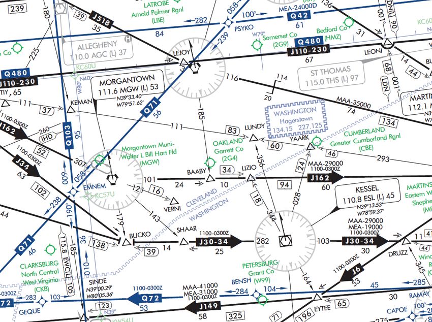
Enroute Chart Examples
Low Enroute Chart
1
2
3
FAA Chart User’s Guide - IFR Enroute Symbology
4 6
5
28AIRSPACE INFORMATION (Continued)
Enroute Chart Examples
Low Enroute Chart (Continued)
Reference Number Description
Multiple MCAs at a NAVAID
1 V21 and V257 - MCA at DBS of 8600’ traveling North
V298 - MCA at DBS of 9800’ traveling West
V343 - MCA at DBS of 8500’ traveling North
V520 - MCA at DBS of 9000’ traveling East
V520 - MCA at DBS of 10600’ traveling West
FAA Chart User’s Guide - IFR Enroute Symbology
MCA and MRA at a Fix
2 MCA at SABAT on V298 of 11,100 traveling East.
MRA at SABAT of 10000.
3 Example of MOCA and directional MEAs along a Victor
Route
Traveling East from DBS, MEA 13,000’ the first two segments,
15,000 along third segment.
Traveling West from QUIRT, MEA of 15,000’ the first segment,
MEA of 10,000 the second segment and MEA of 9,000 the third
segment.
MOCA for DBS to SABAT and SABAT to LAMON segments of
8100
4 MCA Example
MCA at OSITY on V330. MCA of 9500’ traveling East on V330
from Idaho Falls (IDA) VOR-DME.
29AIRSPACE INFORMATION (Continued)
Enroute Chart Examples
Low Enroute Chart (Continued)
Reference Number Description
5 MEA VHF and RNAV Example
MEA for aircraft utilizing VHF NAVAID of 15000’
MEA for aircraft utilizing RNAV of 13300’
MOCA of 13300’
MCA and MTA Example at a NAVAID
6
MCA for aircraft traveling West along V520 to cross JAC at 15200’
MCA for aircraft traveling West along V330 to cross JAC at 13400’
MTA for aircraft crossing over and turning at JAC:
Aircraft traveling NE on V465 and turning to V330 on a W heading
or turning to V520 on a W heading must turn at altitude of 16000’
FAA Chart User’s Guide - IFR Enroute Symbology
or higher
Aircraft traveling E on V520 and turning to V330 on a W heading
must turn at altitude of 14200’
Aircraft traveling E on V330 and turning to V520 on a W heading
must turn at altitude of 16000’ or higher
Aircraft traveling NW on V328 and turning to V465 on a SW head-
ing must turn at altitude of 15100’ or higher.
30Airspace Information (Continued)
Enroute Chart Examples
High Enroute Chart
1
2
FAA Chart User’s Guide - IFR Enroute Symbology
3
Reference Number Description
High RNAV Route with MEA for DME/DME/IRU RNAV
Aircraft
1
MEA of 24,000’
Directional Jet Route with Time Restrictions
Jet Route 34 available between 1100 - 0300Z
2
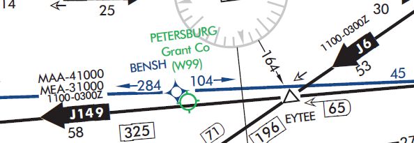
31AIRSPACE INFORMATION (Continued)
Enroute Chart Examples
High Enroute Chart (Continued)
Reference Number Description
Directional Jet Route with Time Restrictions, MAA and
MEA
3 Jet Route 149 available between 1100 - 0300Z
MAA - 41,000’
MEA - 31,000’
AIRSPACE BOUNDARIES
LOW / HIGH CHARTS LOW / HIGH CHARTS
Air Defense Air Route Traffic Control
Identification Zone (ADIZ) Center (ARTCC)
ARTCC Name
ALASKA ADIZ ARTCC Remoted Sites with Site Name
Frequency
FAA Chart User’s Guide - IFR Enroute Symbology
discrete VHF and UHF frequencies
CAN ADA ADIZ
Adjoining ADIZ Air Route Traffic Control Center
(ARTCC) with Controller Pilot
Air Traffic Service LOW / HIGH CHARTS Data Link Communications
Identification Data (CPDLC)
Ceiling
Floor
Call Sign
Frequency
Ceiling
Altimeter Setting Change
Floor
Call Sign
Frequency
LOW / HIGH CHARTS
Flight Information Regions (FIR) Control Areas (CTA)
LOW / HIGH CHARTS
NEW YO RK O CEAN IC CTA/FIR KZWY
MIAMI O C EANIC C TA/FIR KZMA
Adjoining CTA
Additional Control Areas
LOW ALTITUDE
Upper Information Regions
(UIR) HIGH ALTITUDE
CONTROL 1419 H
Upper Control Areas (UTA)
32AIRSPACE INFORMATION (Continued)
Airspace - U.S.
Class A Open Area (White)
High Chart Only That airspace from 18,000’ MSL to and including FL 600,
including the airspace overflying the waters within 12 NM
Controlled of the coast of the contiguous United States and Alaska
Airspace and designated offshore areas, excluding Santa Barbara
Island, Farallon Island, the airspace south of latitude
25° 04’00” N, the Alaska peninsula west of longitude
160°00’00” W, and the airspace less than 1,500’ AGL.
That airspace from 18,000’ MSL to and including FL
450, including Santa Barbara Island, Farallon Island, the
Alaska peninsula west of longitude 160°00’00” W, and
designated offshore areas.
Class B
Screened Blue with a Solid Blue Outline Example:
Low Chart Only
FAA Chart User’s Guide - IFR Enroute Symbology
Controlled
Airspace
That airspace from the surface to 10,000’ MSL (unless
otherwise designated) surrounding the nation’s busi-
est airports. Each Class B airspace area is individually
tailored and consists of a surface area and two or more
layers.
Example:
Mode C Area
A Solid Blue Outline
See Chart example above.
Low Chart Only
That airspace within 30 NM of the primary airports of
Class B airspace and within 10 NM of designated airports.
Controlled
Mode-C transponder equipment is required. (See FAR
Airspace
91.215)
33AIRSPACE INFORMATION (Continued)
Airspace - U.S. (Continued)
CLASS C Screened Blue with a Solid Blue Dashed Outline Example:
Low Chart Only
Controlled Air-
space
That airspace from the surface to 4,000’ (unless other-
wise designated) above the elevation of selected airports
(charted in MSL). The normal radius of the outer limits of
Class C airspace is 10NM. Class C airspace is also indi-
FAA Chart User’s Guide - IFR Enroute Symbology
cated by the letter C in a box following the airport name.
CLASS D Open Area (White) Example:
Low Chart Only
Controlled Air-
space
That airspace from the surface to 2,500’ unless otherwise
designated) above the airport elevation (charted in MSL),
surrounding those airports that have an operational con-
trol tower. Class D airspace is indicated by the letter D in
a box following the airport name.
CLASS E Open Area (White)
Low Chart Only That controlled airpsace below 14,500’ MSL which is not
Class B, C or D.
Controlled Air-
space Federal Airways from 1,200’ AGL to but not including
18,000’ MSL (unless otherwise specified).
Other designated control areas below 14,500’ MSL.
Not Charted
That airspace from 14,500’ MSL to but not including
18,000’ MSL, including the airspace overflying the waters
within 12 NM of the coast of the contiguous United States
and Alaska and designated offshore areas, excluding the
Alaska peninsula west of longitude 160°00’00” W, and the
airspace less than 1,500’ AGL.
34You can also read