Amphibious Robotic Propulsive Mechanisms: Current Technologies and Open Challenges
←
→
Page content transcription
If your browser does not render page correctly, please read the page content below
Chapter 3
Amphibious Robotic Propulsive
Mechanisms: Current Technologies
and Open Challenges

Robert Baines, Frank Fish, and Rebecca Kramer-Bottiglio

3.1 Introduction

Much research effort has been dedicated to underwater robots, as evidenced by
numerous papers and the contents of this book [1]. An even larger body of literature
concerns terrestrial robots. But what about amphibious robots that can operate both
in water and on land? From the literature, we glean that amphibious robots are
fantastic vehicles for studying autonomous navigation strategies in unstructured,
complex environments [2]. Furthermore, they have proven useful as physical models
for gaining deeper insight into the gait patterns and mechanics of animal locomotion
[3–5], analyzing the health of ecosystems [6, 7], and understanding physical
principles underlying propulsion in various media [8, 9]. Beyond the academic
space, advances in amphibious robotics are projected to be a significant boon to
industries such as reconnaissance, surveying, offshore mine detection, and water
quality monitoring, where seamless transitioning between locomotion modes is
critical to success [10–13].
    In spite of their versatility, relatively few amphibious robots have been reported
in the literature. Significant challenges remain for designing, building, and imple-
menting amphibious systems outside of the laboratory setting. Central to realizing
an amphibious robot is designing propulsive mechanisms for effective water- and
land-based locomotion. In doing so, the engineer must strive to balance conflicting
features. As we shall investigate in this chapter, both in natural and physical systems,

R. Baines · R. Kramer-Bottiglio ()
Department of Mechanical Engineering and Materials Science, Yale University,
New Haven, CT, USA
e-mail: rebecca.kramer@yale.edu
F. Fish
Department of Biology, West Chester University, West Chester, PA, USA
e-mail: ffish@wcupa.edu

© Springer Nature Switzerland AG 2021                                                41
D. A. Paley, N. M. Wereley (eds.), Bioinspired Sensing, Actuation, and Control in
Underwater Soft Robotic Systems, https://doi.org/10.1007/978-3-030-50476-2_3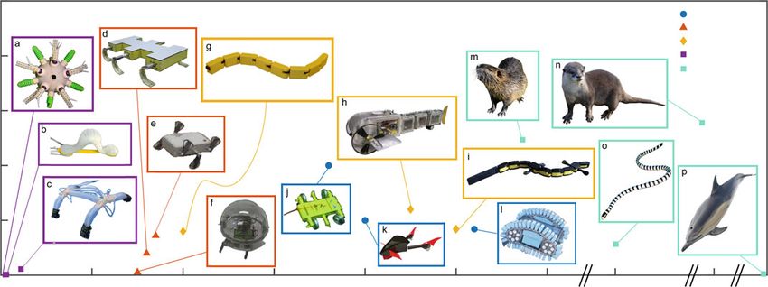
42                                                                     R. Baines et al.

functional shapes conducive to load bearing and terrestrial maneuverability often
detract from hydrodynamic efficiency and water compatibility.
    The transition between water and land, called the littoral zone, also presents
challenges. The littoral zone is characterized as a turbulent environment due to
wave action, intermixing of heterogeneous substrates, suction forces, and abrasive
flows imposed by fluidized sediment. Rocks, shoals, uneven slopes, dense algal
beds, and reefs are all obstacles that an amphibious robot might encounter and
have to negotiate in a transition zone [14, 15]. The dynamic onslaught of physical
phenomena and obstacles in the littoral zone constitute a multi-faceted problem for
which there are no obvious robot design solutions.
    To provide biological inspiration in the design of amphibious propulsors, this
chapter first analyzes animals’ body plans and their locomotor adaptations in
Sect. 3.2. Animal morphology and physiology is, in fact, chiefly influenced by
evolutionary pressures for effective movement in an environment [16]. For the sake
of brevity, we hone in on key examples from semi-aquatic, semi-terrestrial, and
highly specialized species that typify the range of propulsive modes exhibited by
animals.
    With biological context, we transition to a survey of existing amphibious robotic
platforms in Sect. 3.3. Designs striving to address the slew of environmental
challenges amphibious robots face can be broadly classified into systems that
locomote using separate or united propulsive mechanisms. We define separate to
mean that distinct subsystems move a robot on land and though water, whereas
movement with a united mechanism is achieved in both media via the same
subsystem. While separating propulsive mechanisms is a more traditional approach
and may allow robots to locomote with specialized modes of transit in each
environment (i.e., using wheels to move on land and jets to move through water),
uniting propulsive mechanisms has gained popularity as a means of reducing system
complexity and exploring propulsive architectures inspired by amphibious animals
(i.e., using snake-like undulations to move in water and on land) [17]. Beyond
separate and united propulsive mechanisms, we further sort robots into (1) wheeled,
(2) legged, (3) undulatory, or (4) soft categories, based on their body plans and
primary means of propulsion. Section 3.3 further expounds on what distinguishes
these classifications from each other.
    After a synthesis of existing work, Sect. 3.4 identifies promising avenues for
future research on amphibious robotics. Lastly, Sect. 3.5 presents a case study: our
research on a variable stiffness morphing limb, a design that seeks to unite various
propulsive functionalities into a single cohesive mechanism.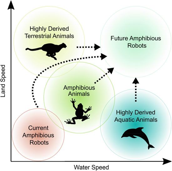
3 Amphibious Robotic Propulsive Mechanisms: Current Technologies and. . .             43

3.2 Biological Perspectives on Amphibious Locomotion

3.2.1 Movement through Different Media

There are physical differences between water and air that determine the different
mechanisms of animal locomotor modes in either environment. Density and vis-
cosity are the most important physical properties [18]; water is 800 times denser
than air and 55 times more viscous. The ratio of inertial to viscous effects is
also of paramount importance to aquatic locomotion [19], and can be expressed
quantitatively via the Reynolds number:

                                             ρU L
                                      Re =        ,                                (3.1)
                                              μ

where ρ is the fluid density, U speed, L characteristic length of the body in the fluid,
and μ dynamic viscosity. We will touch on the ramifications of scale with regard to
specific propulsive mechanisms later. Regardless of scale, swimming animals tend
toward a density close to that of water to support their body weight via buoyancy.
They use the high density and viscosity of the medium to generate hydrodynamic
forces for propulsion. Swimming is accomplished by propulsors that can be broadly
classified as undulatory, lift-based oscillatory, drag-based oscillatory, or jetting [20–
22].
   On land, an animal moves through air, so gravitational forces predominate and
the weight of an animal has to be supported by rigid or hydrostatic skeletons.
Animals apply frictional forces from contact of a body or limbs on the solid
ground for propulsion. Broadly speaking, terrestrial locomotion is enabled by
propulsors that induce undulatory motions, limbed locomotion, a combination of
both undulating and limbed locomotion, or rolling [23–26].
   Many animals are capable of moving between water and land [22]. The reasons
why animals adapted for multi-modal locomotion between water and land stem from
survival adaptations, including catching prey, escaping from predators, mating, and
searching for food [27]. For vertebrate animals, the shift from finned swimming to
legged terrestrial locomotion in the transition from fish to amphibians is considered
one of the watershed events in evolution. Aside from amphibians, mammals,
reptiles, and birds have amphibious species exhibiting varying degrees of terrestrial
and aquatic locomotor adaptations. Amphibious behaviors are also exhibited by
invertebrate lineages, most notably mollusks and arthropods. All amphibious
animals, regardless of classification, must strike a balance between being both semi-
aquatic and semi-terrestrial, and utilize united or separate propulsive mechanisms
for locomotion in either media.
44 R. Baines et al.
3.2.2 Amphibious Animals with United Propulsive
Mechanisms
Numerous amphibious animals exist in nature that utilize the same propulsive
mechanism in both mediums [28]. Amphibians, notably frogs, hop and swim using
a similar movement pattern: maximum extension of hind limbs, followed by a
sweeping recovery phase [29]. Mammalian limbs can relatively easily engage in
drag-based propulsion in water. Drag-based swimming and quadrupedal walking
locomotion modes are embodied by mammals such as muskrats, elephants, and
opossums [30]. When swimming in a drag-based regime, propulsive drag force
is produced only through half of the stroke cycle by the rearward movement of
the appendage, since forward motion is a non-thrust generating recovery phase.
Consequently, limbed amphibious mammals demonstrate high locomotor costs due
to their inability to specialize for water or land [22].
Amphibious reptiles, like freshwater turtles, also utilize united propulsive
mechanisms—swinging of limbs—for drag-based swimming and quadrupedal
walking. Amphibious snakes, on the other hand, leverage bodily undulations to
move in the water and on land. Evolutionary adaptations that enhance aquatic
locomotion at the expense of terrestrial locomotion, such as diminished ventral
plates and a flattened tail, can be observed between some species of snakes. [31].
Mollusks like the octopus represent a rather unique case in that they use unsupported
limbed locomotion to crawl along the ocean bottom and on land [32].
Propulsive mechanisms for amphibious animals that walk both on the surface of
water and on land are very much governed by size. Small animals with hydrophobic
surfaces, such as water striders, can exploit surface tension to support the body [33].
As the size of an animal increases, surface tension becomes insufficient to support its
weight. The basilisk lizard can run atop water by simultaneously generating surface-
level drag and expanding an air cavity underwater [34]. As the size of a basilisk
lizard increases, the kinematics of the foot stroke change to keep it atop the surface
[35]. For even larger organisms, like aquatic birds, movement atop water requires
the addition of broad wings impacting the surface [36].
3.2.3 Amphibious Animals with Separate Propulsive
Mechanisms
A less common model in nature than united propulsive mechanisms is to utilize
separate propulsive mechanisms for either medium. Among mammals, otters engage
in quadrupedal walking and undulatory swimming [37]. Reptiles of the order
Crocodilia, including alligators and crocodiles, use tail undulations in the water but
rely on quadrupedal gaits on land. Similarly, newts and salamanders undulate their
bodies in a standing wave while using their limbs to walk [28]. Some at high speeds
will undulate on land with their legs tucked in to their sides.3 Amphibious Robotic Propulsive Mechanisms: Current Technologies and. . . 45
3.2.4 Specialization for Water or Land
Generally, semi-aquatic or semi-terrestrial animals—like those mentioned up to this
point—are less energy efficient and slower (in terms of body lengths per second)
than animals that are specialized for one environment [22]. Yet in engineering, an
amphibious robot is not limited by the same physiological factors that limit animals.
Animals must move by oscillations of appendages or body undulations powered
by muscles, must respire with gills or lungs for oxygen to fuel cells constituting
their muscles, are composed of biomaterials such as bone, cartilage, and chitin
that have lower strengths compared to metals used in engineered systems, and
have a large portion of the body devoted to reproductive functions. An amphibious
robot can take advantage of specialized, rapid, and efficient aquatic and terrestrial
propulsive mechanisms, or those that are dangerous for animals [5]. It is thus worth
enumerating some of the more optimal propulsive mechanisms and body plans for
water and land exhibited by highly derived (specialized for certain environments as
a result of evolution) species.
Inhabiting an exclusively aquatic environment, tuna and dolphins have stream-
lined, hydrodynamic bodies and rely on oscillation of their caudal fins to generate
thrust as a vector component of lift. Other fast and efficient aquatic animals with
lateral fins and flippers can produce thrust by undulatory (bluegill, sunfish, stingray)
swimming, as well as oscillatory wing-like movements (sea lion, sea turtle). Though
not sustainable over long periods, jetting can enable rapid accelerations and is
seen in jellyfish, squid, and octopus. Larger aquatic animals, like those mentioned
above, are considered to be nekton, that is, capable of swimming long distances
independent of water currents. Nektonic animals swim at high Reynolds number
(Re > 103 up to 108 ) [38]. At high ranges of Re, swimming is performed by
accelerating a mass of water for propulsion. Viscous forces are small, whereas
inertial forces are large [38]. Yet the overwhelming number of animals that exist in
the oceans are small, like plankton, and use ocean currents pushing on their bodies
as a propulsive mechanism to move long distances. Most planktonic animals (e.g.,
copepods) lie within an intermediate range of Re (1 < Re < 103 ), where viscous
and inertial forces are both important [39]. At even smaller scales, bacteria cilia and
flagella operate between 10−5 and 10−6 Re, where viscous effects dominate [40].
Terrestrial vertebrates are generally not streamlined. They have a defined neck,
no blubber to contour the body shape, and if they have limbs, the limbs are generally
cylindrical with an approximately circular cross section. As size (and thereby
mass) of a terrestrial organism increases, gravity becomes a more dominant force,
unlike in water where weight is supported by buoyancy. Among limbed terrestrial
animals, peak limb stresses can increase with increasing body size, so posture of
the skeletal elements of the legs tends toward a more columnar (upright) stance
[41, 42]. Such a change in posture maintains a safety factor independent of size, but
at the expense of accelerative capability and maneuverability. Horses and cheetahs
are exemplar animals with skeletal components disposed to upright walking and
high-speed linear galloping. Highly derived terrestrial animals, like the horse and46 R. Baines et al.
cheetah, exploit spring-like interactions of their body with the ground to enhance
thrust produced with each stride [43]. The storage and release of elastic energy
as a propulsive mode actually increases in efficiency at higher speeds in some
animals [44]. In addition to limbed propulsion aided by elastic potential energy
storage, it is instructive to mention another (perhaps more unusual) specialized
terrestrial propulsive mechanism that harnesses gravity: rolling. Passive rolling is
demonstrated by arachnids, while species of caterpillar actively build up angular
momentum during rapid escape maneuvers [26]. Top speeds of rolling animals can
be an astounding tens of body lengths per second.
3.2.5 Biological Inspiration for Design of Amphibious Robotic
Propulsive Mechanisms
Both environmental medium and scale influence an organism’s propulsive mech-
anism adaptations. The intermediate status of amphibious animals compromises
their locomotive performance in either environment, but the mechanics of these
intermediate species can potentially serve as a template to develop a new generation
of amphibious robots. Furthermore, amphibious robots can be designed to incorpo-
rate locomotor mechanics that are specialized for either environment or any scale,
expanding upon what nature has been capable of producing through evolution.
It is thus the charge of the robotic designer to synthesize various propulsive
mechanisms and corresponding body plans found in nature—even to look beyond
these natural examples to synthetic solutions—to innovate and produce an effective
amphibious robotic system. Such a methodology to realizing future amphibious
robots is depicted in Fig. 3.1. The next sections review current work in amphibious
robotics. An exposé of novel designs, biologically inspired or of purely synthetic
origin, as well as the advantages and disadvantages of these designs, supplies
additional foreknowledge to synthesize next-generation amphibious robots.
3.3 Classification of Amphibious Robots
A strict template for classification does not necessarily encompass any given robot’s
propulsive mechanisms. While robots with united propulsive mechanisms may be
much easier to classify, robots with separate propulsive mechanisms defy any strict
classification. For the sake of review, we sort amphibious robots into wheeled,
legged, and undulating based on the most salient aspect of their morphologies.
Wheeled, legged, and undulating amphibious robots utilize significantly different
mechanisms to move in water and on land. Wheeled systems include rounded
entities concentric to axles that, when engaged in rolling, provide leverage based
on the radius. Wheels can be driven passively (by gravity) or actively (by motors).3 Amphibious Robotic Propulsive Mechanisms: Current Technologies and. . . 47 Fig. 3.1 Combining knowledge of the propulsive mechanisms of amphibious animals, the spe- cialized mechanisms exhibited by highly derived species, and existing amphibious robot designs is key to developing the next generation of amphibious robots. Note that the relative positioning of groups is based on the authors’ qualitative assessment of performance In water, movement of treads through the fluid medium can serve as discretized paddles for drag-based thrust. On land, wheels rest on the ground at all times and rely on friction contact force on the substrate at a point and repetitive revolutions to generate a thrust vector. Legs are a more generic morphology. They can be articulated, multi-degree- of-freedom, or single degree-of-freedom links of various shapes and kinematic configurations. In water, legs engage in oscillations or power strokes to generate thrust. On land, legged systems utilize discrete footholds to move. The body is supported off the ground with either upright or sprawled legs. Having a lower center of mass, sprawled posture is generally more stable than the full upright orientation of legs. A robot’s legs must leave the ground in periodic increments to achieve bodily displacement. Undulating robots come in elongated forms, often consisting of a series of modules connected together. In water, undulatory swimmers display a gradient of propulsive modes for thrust production—from undulatory waves encompassing the total length of the body (anguilliform), through progressively expanded posterior regions of the body (carangiform), culminating in thrust production confined to the
48 R. Baines et al.
Wheeled/tracked Legged Undulating Soft
Water
Land
Fig. 3.2 Amphibious robots sorted into four distinct categories based on their primary propulsive
mechanisms and structural features: wheeled/tracked (note, wheels are half-submerged in water
in the depicted image), legged, undulating, and soft. Here, we illustrate how each category might
unite the same propulsive mechanism, or transform its limbs or body plan to accommodate water
and land
caudal fin (thunniform). On land, undulating robots move in a fashion characterized
by multiple surface contact points. Waves passing posteriorly down the body push
on solid substrate for forward movement.
Soft amphibious robots may locomote in a way that is consistent with the
previous three delineated categories, but are distinguished by their composition of
continuously deformable materials, typically having a Young’s modulus on the order
of, or less than, one MPa. Consequently, soft robots do not commonly use traditional
rigid motors. Reliance on soft actuators [45] is thus another factor that separates
them from the other three categories.
Figure 3.2 depicts how each category might unite the same propulsive mech-
anism, albeit with morphological transformations present in the legged and soft
categories. Each category is associated with a unique set of advantages and
disadvantages that motivate discussion on what constitutes an effective amphibious
robot design. The following subsections address each of the classes of robots in
the listed order. For each, we open with a discussion of its respective advantages.
We then highlight seminal amphibious robots belonging to that class. Our intention
is to not to detail every amphibious robot reported in literature, but to summarize
key innovations as embodied by the seminal designs. Aspects we focus on when
appraising an amphibious robot are its capacity to bear payloads (i.e., sensors,
camera, equipment; this criteria is of course dependent on size), ease of control,
efficiency, maneuverability, and speeds in water and on land. Aside from absolute
speeds in water and on land, which we have plotted against each other for a
number of designs and comparably sized animals in Fig. 3.3, the other metrics are
not consistently reported for amphibious robots throughout literature. We instead
provide a qualitative assessment of these metrics. Each section closes with a
synopsis of a particular class’ drawbacks, and therefore opportunities for future
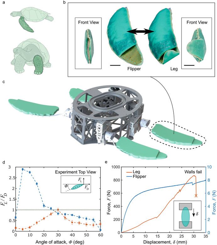
research.Fig. 3.3 A comparison of absolute sustained speeds between representative amphibious robots from each of the delineated categories, as well as semi-aquatic,
semi-terrestrial, and aquatic animals. Note that many of the increases in robots’ speed have naturally come hand-in-hand with improved research hardware,
3 Amphibious Robotic Propulsive Mechanisms: Current Technologies and. . .
such as higher torque motors and lower footprint microcontrollers. We try and account for this factor by featuring a variety of older and newer published
work from each category. Citations for (a–l) are [4, 6, 9, 46–54]. We include comparably sized animals operating in a similar Reynolds regime (thus excluding
whales, bacteria, etc.) for comparison to the robots. The animals are from (m–p): muskrat, river otter, yellow-lipped sea krait, and bottlenose dolphin. Citations
for speeds (m–p): [37, 55–59]
4950 R. Baines et al.
3.3.1 Wheeled and Tracked Amphibious Robots
Wheels represent a unique propulsive mechanism for amphibious robots since,
compared to legs and undulations, wheel-like forms are less readily used in nature
[26]. On land, wheels pose an energetic benefit because when traveling at a
constant speed, the kinetic energy remains constant [40]. Compare this energy
profile to most other natural propulsive mechanisms that necessitate trajectories of
cyclic acceleration and deceleration that may incur a sizable energy cost. It is not
surprising then, that a common—and perhaps the simplest—propulsive mechanism
for amphibious robots is wheels or tracks.
A ubiquitous amphibious robot design, similar to many amphibious vehicles,
uses wheels to move on land and on top of water. Such robots are far along in the
development pipeline and are commercially available [60]. Though rotating wheels
to move in water and on land unite the same propulsive mechanism, simplifying
control, it comes at the expense of speed in water. Speed is limited because wheels
increase drag due to the heightened relative velocity from the rotation of the wheel,
which can induce flow separation [61].
Yamada et al. built what appears to be a quintessential wheeled amphibious
robot, but with a clever twist for improved aquatic locomotion. Their four-wheeled
platform, R-Crank, incorporates a ribbed crank link between its front and back
wheels on each of its sides. The crank link generates thrust for surface-based aquatic
locomotion as the tires spin [62].
While the previously mentioned robots include wheels as a part of their hardware,
other robots are, by no stretch of definition, wheels. A design perk of wheel-bodied
robots over robots with wheels is that the need for a bulky chassis is eliminated,
reducing weight, and potentially conferring hydrodynamic benefits. Consider that
the drag force on a body is
ρV 2
F D = CD A , (3.2)
2
where CD is the drag coefficient, ρ is the density of the fluid, V is the flow velocity
relative to the body, and A is the reference area. Note removing a chassis will
substantially decrease A. Also, the CD of a wheel, typically shaped like a sphere
or disk can be much lower than typically angular, rectangular chassis.
One wheel-bodied system, Groundbot, was developed by Rotundus AB in
Sweden as a multi-terrain surveillance robot. Spherical, treaded, made of rubber, and
fully resembling a tire, Groundbot can roll and steer itself using an offset internal
weight actuated by motors. It boasts up to 3 m/s (5 bl/s) sustained speeds on level
ground. It employs the same rolling mechanism to traverse water as it does for land,
floating atop the surface and generating thrust with its specifically engineered treads
that essentially serve as a series of paddles [63].
Another robot with a wheel-like body is the triphibious MUWA. MUWA consists
of a ring of polystyrene foam surrounding a multicopter. The polystyrene ring gives3 Amphibious Robotic Propulsive Mechanisms: Current Technologies and. . . 51 MUWA enough buoyancy to float atop water, but also provides geometry conducive to rolling. When rolling on land, MUWA controls its trajectory by adjusting the pitch of its rotating propellers [64]. Transition areas rife with loose or fluidized sediment threaten to ensnare wheels. Rolling resistance of wheels increases in proportion with soil compliance [65]; in fact, one study found that rolling resistance on concrete can be 10–15 times less than that of sand [66]. Terramechanics research models physical interactions with the substrate and provides an estimate of the extent to which sinking into the substrate impedes motion [67]. Concentrated weight is a primary cause of local soil fracture, causing ensnarement. Tracks distribute the weight of a robot over a larger area to mitigate sinking and improve locomotion across muddy terrain, but may sacrifice some speed and maneuverability. Tracked amphibious robots have been built that are intended to sink below the surface to crawl on lake beds [11]. Sinking to the bottom is not always practical, though. Motivated by the need to monitor an estuary system composed of multiple rapid transitions from shallow water to soggy land, one robot was designed with buoyant tracks so it can engage in surface swimming while retaining the ability to navigate muddy sections [6]. This surface-swimming robot has the fastest speed on water reported in Fig. 3.3. The aforementioned wheeled or tracked designs have not demonstrated ability to swim in 3D. For certain applications, amphibious robots need to be able to engage in 3D swimming so that they can transition between the surface and underwater and explore the water column in between. In order to enable 3D swimming while retaining the merits of wheels on land, one group introduced a class of robot with hybrid wheels/propellers and separate fins [53]. The hybrid wheels/propellers have spokes emanating radially from the termination of their axle, effectively providing the hydrodynamic thrust of propellers and generating sustained speed of up to 0.36 m/s (0.375 bl/s) in water (Fig. 3.3j). The fins on the robot are used to steer when swimming. Owing to its wheeled design, this robot also exhibits the top speed on land out of all designs in Fig. 3.3, at 1 m/s (1.04 bl/s). Transitions from aquatic to terrestrial locomotion are accomplished by orienting the wheels/propellers so their revolution will provide forward thrust in water or serve as a wheel on the land. Another hybrid wheel/propeller mechanism that allows for 3D swimming, dubbed the eccentric paddle, consists of a shaft embedded in a wheel on which paddles are radially distributed. The paddles move in and out of the wheel to adjust the extent of their interaction with the environment. Equipped with eccentric paddles, the robot demonstrates an unusual capability: a quasi-walking mode of locomotion by cyclically protruding the paddles from the wheel [68–70]. Offering the speed of wheels as well as aquatic mobility, hybrid approaches, like combined wheels/propellers and separate fins or the eccentric paddle, nonetheless rely on complex agglomerations of mechanisms that are difficult to control. Such intricate hybrid mechanisms with many moving components may also be susceptible to debris in the littoral zone compromising their function. Overall, although they offer efficiency and high top speeds on flat land and the requisite structural integrity to support large payloads, a major drawback of wheeled
52                                                                     R. Baines et al.

and tracked robots is their lack of ground clearance and consequently diminished
ability to traverse uneven terrain [71, 72]. Heavy systems with wheels, specifically,
have a propensity to become trapped in shallow, fluidized sediment [73]. Moreover,
wheels do not scale well to small sizes because they become sensitive to substrate
compliance and uneven terrain impacting forward motion [40]. A promising design
strategy, creating a wheel-bodied robot or a hybridized paddle-wheel mechanism,
can reduce mass, enable 3D swimming, and address minor challenges posed by
uneven terrain [53, 70]. Yet, hybrid mechanisms can be plagued by their host of
moving parts, especially in the littoral zone rife with obstacles. If creating hybrid
mechanisms, designers should err on the side of simplicity to provide resilience
against environmental detritus. Lastly, robots with wheels or tracks can leave
destructive trails behind them—a heavy wake or dislodged soil. While observing
fragile ecosystems or trying to maintain stealth, disturbances to the environment
can undermine mission success. More work on wheeled systems that minimize
environmental impact thus represents an open area of research. When navigation
of uneven terrain or stealth are prerequisites to a successful mission, other types
of amphibious robots might be better options than current designs with wheels or
tracks.

3.3.2 Legged Amphibious Robots

Legged amphibious robots tend to be more complex in design and control archi-
tecture than wheeled robots due to the multiple controlled degrees of freedom
associated with each leg. Primary advantages of legged robots include their
capability to traverse obstacles wheels or tracks cannot, and need for only discrete
footholds to locomote, as opposed to a continuous supporting surface. On especially
soft ground, legged robots deform terrain less than wheeled or tracked systems and
thereby can diminish the energy required for traversal [74]. Due to their multiple
degrees of freedom, legged robots can also change direction without slippage.
Like wheeled robots, legged robots can sustain concentrated payloads undulating
robots cannot, since their motion is not dependent on dynamic oscillations of
interconnected bodily modules.
   Spurred by calls to develop systems to locate and destroy mines in the surf zone,
one of the first examples of a legged amphibious robot—let alone one of the first
amphibious robots—was published in 1996. The report detailed a hexapod robot,
Ariel, inspired by the crab that walks at a shallow depth along the seabed [12].
Since Ariel, similar work has been published focusing on the creation of lobster-
inspired robots with the same purpose [75]. A major concern for benthic walking
robots is the large hydrostatic pressures associated with great depths—not only for
water-proofing but also for feasibility of walking. Large moments would be created
about the leg joints at depths, and it is unlikely compact actuators could overcome
such moments.
3 Amphibious Robotic Propulsive Mechanisms: Current Technologies and. . .          53

    In contrast to robots that crawl along the seabed are surface walkers: amphibious
robots inspired by insects and reptiles (mentioned in Sect. 3.2) that are able to walk
on the surface of water by exploiting the physical properties of their feet, and/or
their small body mass. Park et al. presented a platform inspired by the basilisk
lizard. The crux of their design revolves around a light-weight robot body and a
compliant foot pad, which transfers elastic energy to propulsive momentum [76–78].
Yet such a robot cannot bear payloads that would compromise its light weight and
would therefore be limited to minimal integrated circuits. Another surface-walker-
inspired robot is bulkier and able to bear payloads, compensating for its increased
weight via Styrofoam spherical feet that provide buoyant forces [79]. A cockroach-
inspired microrobot fabricated by Chen et al. uses partially submerged foot pads to
paddle on the surface of the water, exploiting surface tension. Unlike the previous
two mentioned platforms, it is able to dive from the surface to the bottom by emitting
high voltage from its padded feet to temporarily break surface tension. It can then
walk on underwater surfaces as it does on land [80]. Nevertheless, the robot is unable
to replicate the speed and dexterity of an actual water strider due to constraints on
the force density of such small actuators. In addition to those mentioned, there have
been a variety of other surface-walking robots [81].
    Though bottom and surface walking may be sufficient in some scenarios,
3D swimming offers greater surveying capability. To this end, a new chapter in
amphibious legged robotics started with AQUA [82, 83]. AQUA, based on Boston
Dynamics’ R-hex platform [84], utilizes six independently controlled paddles on
single degree-of-freedom (DOF) joints as control surfaces during swimming. It also
has interchangeable, curved cockroach-style legs for walking that act as springs,
efficiently storing and releasing potential energy with each stride. AQUA represents
the first robot of its kind—legged, able to proficiently move on land and traverse
obstacles, but also able to engage in 3D swimming to fair depths. There are many
subsequent amphibious robots that drew design inspiration from AQUA’s body plan
and leg design.
    One series of robots inspired by AQUA are hexapods equipped with Whegs™
(a portmanteau for wheel-legs). Whegs™ integrate swimming and walking mecha-
nisms, combining the simplistic control of a wheel with the articulated cadence and
ability to traverse some obstacles that legs typically can [85]. Whegs™ are similar
to the cockroach-style legs initially equipped to AQUA, but are built with three
protruding paddles equally distributed radially about the center shaft, as opposed
to AQUA’s single paddle. Whegs™ have been implemented on amphibious robotic
platforms as a combined propeller/wheel with great success [86–88]. Despite their
critical appeal, it should be noted that the drag-based propulsion supplied by
Whegs™ is inefficient relative to lift-based locomotion [30]. Also, like propellers,
Whegs™ induce turbulent vortices that may pose too much of an environmental
disturbance for some applications. Lastly, the geometry of Whegs™ does not allow
backwards locomotion on land (the paddles contact the ground at a point, acting as
a rigid rod and stunting motion), which detracts from their terrestrial mobility.
    Bearing strong resemblance to Whegs™ -style robots but with modifications to
address the fact that Whegs™ are not able to back-drive, Ninja Legs incorporate a
54 R. Baines et al.
thin circular wire enclosure around flippers. The enclosure protects the compliant
flippers and simultaneously serves as an offset wheel for hybrid rolling/walking
[89]. In a similar vein as Ninja Legs, one robot named RoboTerp unites flippers and
legs into a single hybrid propulsion mechanism. The structure of one limb consists
of a flap passively hinged to a grate. The grate serves as a rigid load-bearing leg
to support the robot’s weight on land. While swimming, during the robot’s power
stroke, the flap flattens against the grate thereby increasing paddle surface area and
producing forward thrust. On the upstroke, the flap freely swings back, reducing
drag [90].
RoboTerp’s passive paddle mechanism is not conducive to high aquatic mobility.
This reinforces the observation that walking legs, in addition to producing less thrust
compared to more hydrodynamic, high aspect ratio surfaces, are far from optimal
forms for maneuvering in the water. Indeed, the original AQUA platform had
separate flipper and leg modules for water and land, respectively, optimized inde-
pendently of one another. However, the need for human intervention to manually
exchange limb designs undermines a system’s ability to autonomously transition
between environments.
One group introduced AmphiHex-I (Fig. 3.3d) and in doing so initiated a
new amphibious legged robot design paradigm. AmphiHex-I [48, 91, 92] features
a transformable leg-flipper propulsion mechanism. The leg-flipper consists of
interlocking rigid segments connected via a cable. When the cable is pulled, the
interlocking segments are compressed to create a curled cockroach-style leg. When
released from tension, the limb becomes a compliant flipper. Although the robot’s
speeds of 0.16 m/s (0.18 bl/s) underwater and 0.2 m/s (0.23 bl/s) on land rank lower
middle-tier in Fig. 3.3, the AmphiHex-I design philosophy seems promising in terms
of efficiency. Namely, as opposed to relying on separate propulsive mechanisms
that may impede each other’s performance, or a united propulsive mechanism
that sacrifices specialization for average performance, transforming a propulsive
mechanism’s shape offers the ability to greatly hone locomotive performance in
both environments.
After AmphiHex-I came AmphiHex-II (Fig. 3.3e). This robot introduced an
entirely different mechanism than AmphiHex-I: manually adjustable variable stiff-
ness legs. Its semi-circular legs are rigid, fan-shaped frames, and protect flexible
flippers within. By adjusting a pin joint along the leg’s length and the robot’s
chassis, one can set the leg to five different stiffnesses. Experiments with the robot
underscore that modulating the stiffness improves locomotive performance based on
fluid content in a soil-like terrain. It was found that higher stiffness limbs allow the
robot to locomote fastest in sandy substrates and soft soils. An intermediate stiffness
was found to be more efficient for locomotion in fluidized (25%) soil reminiscent of
the littoral zone. Lastly, for swimming, the researchers found the highest stiffness
elicited maximum achievable, sustained velocity [9].
Though legs give a robot the ability to skillfully traverse a wide swath of terrain,
legged robots are generally slower and less energy efficient on flat land, especially
when compared to wheeled robots [5]. Moreover, control of legged robots is much
more complex than that of wheeled robots. Particularly in the aquatic environment,3 Amphibious Robotic Propulsive Mechanisms: Current Technologies and. . . 55
controlling legs as hydrodynamic surfaces for efficient propulsion represents an
open area of research. Whegs™ -style legs simplify the control problem by replacing
articulated joints with just 1-DOF. However, Whegs™ , as well as a majority of
the legged amphibious robot designs mentioned, employ drag-based paddling to
move through water. As mentioned, paddling is not an efficient mode of swimming,
because thrust is only generated in half of the stroke [30]. Thus, alternative modes
of aquatic locomotion must be explored and mechanisms developed to achieve those
modes. One example of an alternative locomotion mode, incorporating separate jet
nozzles on the bottom of a robot’s legs [49, 93], seems like a promising strategy
but requires highly complex modeling of jet orientation to optimize locomotion
(moreover, this specific robot is extremely slow, as seen by its relative position in
Fig. 3.3f). If land speed, hydrodynamics, or control complexity are precursors for a
successful mission, legged amphibious robots may not fare well.
3.3.3 Undulating Amphibious Robots
The third class of amphibious robots is undulating robots, often those with a
serpentine body. Key advantages of undulating robots are their high maneuverability
in water, small turning radii on land, and multiple DOF that lend themselves to
novel locomotion strategies and negotiation of restricted spaces. Arguably one of
the most significant jumps in amphibious robotics coincides with the advent of the
snake-inspired robot, AmphiBot. Unlike other land-based snake robots of the time,
AmphiBot is capable of swimming and crawling, all with the same mechanism:
undulation [17, 94]. AmphiBot’s body is composed of interconnected, indepen-
dently actuated modules. Selective actuation of each of the modules via a central
pattern generator allows AmphiBot to undulate to move smoothly through water
with a speed of 0.2 m/s (0.26 bl/s). However, it has wheels to overcome friction and
attain higher speeds on land. In terms of relative speed to other robots, AmphiBot
falls into the middle of the pack (Fig. 3.3g). Subsequent to AmphiBot, there have
been a fair number of snake-like robots capable of amphibious locomotion. These
follow-ups make slight variations to hardware in efforts to generate more productive
thrust with each oscillation, such as including radially distributed wheels around the
body, and placing continuous ridges along the body [95–97].
One group sought to integrate undulatory caudal fin swimming, propeller-
generated thrust, and flipper-like control surfaces for locomotion in water with
wheels for locomotion on land: the results were Amphirobots-I and II [98, 99].
Amphirobots are composed of a multi-link serial chain whose units possess passive
wheels and has axles that can swivel both laterally and dorsoventrally, unlike pre-
vious amphibious undulating robots. This clever mechanism enables both dolphin-
and fish-style swimming up to 0.45 m/s (0.64 bl/s) as well as serpentine crawling
on land of 0.6 m/s (0.86 bl/s), positioning Amphirobot-II near the top of those
surveyed in both categories (Fig. 3.3h). Caudal oscillation in the fashion of some
fish happens to yield one of the lowest costs of transport among swimming modes as56 R. Baines et al.
mass increases [22]. Yet, Amphirobot’s agglomeration of components increases the
projected area in Eq. (3.2), proportionally increasing drag, countering to some extent
the merits of the efficient propulsive mode. Additionally, as mentioned, having
multiple separate propulsive mechanisms obfuscates control, which the authors
concede reduces the efficacy of their system [98].
The most recent amphibious undulating robot at the time of this writing
originated at Pliant Energy Systems, an energy firm based out of Brooklyn, NY.
Their robot, Velox, consists of a static, rigid body lined with two sets of dynamically
undulating, elongate fins [100]. These fins are based on Pliant’s blade-less energy-
harvesting turbines that passively harness fluid flow. A geared transmission system
internal to the robot pulls parts of the flexible fins up in a wave. The resulting
coordinated undulation endows the robot with high mobility over a variety of terrain.
Videos of the robot traversing snow, flat ground, and swimming freely in three
dimensions testify to its effective united propulsive mechanism design [101].
Despite its superiority in water, undulating propulsion over land has several
drawbacks. First, ongoing challenges with snake-like robots are to get them
to traverse uneven terrain, and developing appropriate contact models for such
traversal [102]. Second, undulation relies on high surface area contact between a
robot’s body and the underlying substrate. Friction or smoothness of a substrate
therefore governs cost of transport much more than a legged robot experiencing
less surface contact. Although friction issues have been partly addressed via the
incorporation of passive wheels onto multi-segment robots, wheels are bulky
protrusions to a robot’s body plan that may further reduce ability to clear obstacles.
From a hydrodynamic perspective, wheels can incur undesired drag forces. Thus it
stands as an open challenge to devise undulating robots that modulate their substrate
friction coefficient without negatively impacting other aspects of locomotion. Third,
serpentine undulating robots do not generally have the capacity to bear large,
centralized payloads due to size limitations of the modules composing their bodies.
More work on centralized chassis-based undulating systems, like Pliant Energy
Systems Velox, represents a promising future direction in this regard. In brief, if
desiring a simplistic platform for transporting larger payloads or navigating uneven
ground, current undulating robot designs may fall short.
3.3.4 Soft Amphibious Robots
The fourth and final class of amphibious robot, ones made primarily of soft
materials, constitute a subset of the already small body of literature pertaining
to amphibious robots. It is well-established that robots can benefit from new
research in soft, responsive materials [45, 103]. The properties of soft materials—
compliance, continuous deformation, stretchability, incompressibility, conference
of hydrodynamic benefits [104, 105], and resilience to damage and harsh conditions
[106]—make them apt candidates for incorporation into amphibious robotics.3 Amphibious Robotic Propulsive Mechanisms: Current Technologies and. . . 57 To the best of our knowledge, the first explicitly declared soft amphibious robot was developed by Faudzi et al. Inspired by the salamander, the robot has an elongated body with short legs. The body and legs consist of McKibben pneumatic actuators. Though quite slow, selective contraction of McKibbens on various parts of its body enables the robot to traverse solid ground, sand, and patches of shallow water [47]. To enable underwater crawling of an amphibious soft robot, Tang et al. integrated two switchable adhesion actuators on distal ends of a bending actuator. Their robot can execute inchworm-style gaits while adhered to both submerged and dry substrates [46]. The salamander-inspired robot and the underwater inchworm-like crawler, being composed of entirely soft actuators, likely cannot bear significant payloads. Another amphibious crawling robot that demonstrated payload capacity and separated its soft actuators from its body is the un-tethered sea urchin-inspired robot developed by Paschal et al. [107]. The sea urchin bot consists of a rigid body, rigid spines, and soft bending actuators (analogs to tubercle feet on a real sea urchin). A unique aspect of the sea urchin robot is that it uses actuation of rigid spines in tandem with bending actuators to engage in bio-mimetic, in-place turning motions. The robot is also able to drag itself on land or under the surface of water. In spite of its high mobility, the robot is confined to ferrous surfaces because it relies on embedded magnets in the tips of its bending actuators for anchor points while dragging [107]. In another instance of utilizing separate soft actuators on a rigid robot body, soft pneumatic bending actuators were equipped as legs to an amphibious dog-inspired robot. The soft actuators were not implemented in a traditional sense, as with the previous two examples. Instead, they are pre-inflated and routed with cables. By pulling on the pre-inflated actuator with the cable, it straightens. Upon release of the tension in the cable, the actuator’s stored energy snaps it back into the bent configuration. The researchers leveraged this mechanism to show the dog-inspired robot trotting on land and dog-paddling in water [4]. Though they provide sufficient force to propel the robot to land speeds of 0.18 m/s (0.34 bl/s)—a rate much faster than other soft amphibious robots—the pre-inflated actuators necessitate additional motors to pull the attached cables. The same material properties that make soft amphibious robots flexible and resilient impede their locomotive performance. Soft amphibious robots substantially lag behind their rigid counterparts in terms of their reported maximum sustained speeds, as indicated by Fig. 3.3a–c. Lack of speed can be attributed to the dissipative effects of soft materials and the low force density of soft actuators relative to motors used on rigid amphibious robots. An open design challenge is thus to enhance speed of soft robots, both in water and on land, while retaining their desirable rheological properties. A wealth of soft actuation schemes that still have yet to be applied to amphibious soft robots, including shape-memory materials, chemically induced volumetric expansion, dielectric elastomers, and combustion [108–110], might facilitate higher speeds. A second drawback is soft robots’ lack of payload- bearing capabilities. Even if they could be designed to move faster, entirely soft structures would buckle under external loads. Fortunately, recent work regarding granular and layer jamming and variable stiffness polymers offers novel ways to
58                                                                        R. Baines et al.

endow a compliant robot with rapid stiffness-changing capacity [111–115] and
might prove useful if applied to amphibious soft robots.

3.4 Overarching Challenges

As evidenced in the literature, the exact design specifications for an amphibi-
ous robot traditionally depend on the task it is intended to complete. In some
applications, like shoreline monitoring, capability to traverse muddy terrain and
surface-level immersion in water with a small camera will suffice to complete all
mission objectives. Other applications, however, like routine inspections of offshore
rigs, may mandate climbing uneven terrain and deeper dives with specialized sensor
suite payloads.
    The various presented propulsive mechanism architectures—wheeled, legged,
undulating, and soft—bring their own unique sets of advantages and disadvantages
to the design table. As research strives to realize increasingly autonomous systems
that are not specifically designed for a task, but rather are multi-functional entities,
the following question stands: how does an engineer synthesize current amphibious
robot propulsive mechanism designs to create new, highly effective ones? To help
guide answers to this question, let us observe facts about the current state of robotic
technology and review areas for improvement in each category.
    Amphibious robots of all categories are outclassed by animals in terms of
absolute speed, as shown in Fig. 3.3. Even the state-of-the-art robots that operate
exclusively terrestrially or underwater fall short of animals in terms of max sustained
speed (both in body lengths per second and absolute speed), operational duration
capacity, acceleration, turning ratio, ability to maneuver in compact spaces, cost
of transport, and stealth [116, 117]. Though metrics other than speed are not well
reported in the literature for amphibious robots, one can infer that amphibious robots
suffer from the same shortcomings (maybe more so) as their exclusively terrestrial
or aquatic counterparts. With these observations in mind, improvements in the force
density and compactness of actuators would be a significant leap for the field.
    Wheeled amphibious robots could become much more effective if they are
augmented to accommodate uneven terrain, swim in 3D, mitigate flow separation
from wheel surfaces in water, and reduce environmental impact. Many of these
improvements could be made by creating hybrid mechanisms that augment wheel
morphology.
    Legged platforms would benefit from simpler control policies (and correspond-
ingly, actuation systems), as their lack of deployment in field missions to-date is
attributed to complex control [118]. Existing force models for legged locomotion
on granular media rely on assumptions of size and uniformity of particulates
[119] that diminish their accuracy in the highly unstructured littoral zone. Thus,
more detailed experiments should be conducted focusing on legged locomotion in
fluidized sediment to converge on robust physical models that can inform actuation
policies. Second, legged systems can be improved by hydrodynamic form factors,
3 Amphibious Robotic Propulsive Mechanisms: Current Technologies and. . . 59
or more generally, ways to augment morphology between functional terrestrial and
aquatic streamlined shapes.
Undulating robots could be modified for enhanced ground traversal. In con-
trast to limbless animals that can navigate almost any surface [120], undulating
robots struggle with uneven surfaces or low friction coefficients [102]. Snake
locomotion strategies of undulation, including concertina motion (used to move
through restricted spaces like tunnels), sidewinding (limited to sandy terrain), and
rectilinear movement (uses bottom scales to move without undulations of the body;
useful for moving along tree branches), have been applied to robotics, but are
far from mirroring the fluidity and efficiency of natural systems [102]. Simplified
controllers that can replicate the diversity of complex undulating gaits would thus
expand the utility of undulating amphibious robots. As with legged platforms, a
fundamental understanding of undulating propulsion over fluidized sediment needs
comprehensive experimental analysis and could help inform locomotion policies for
littoral zones. Lastly, the lack of large centralized payload capability seems to be an
inherent shortcoming of undulating. One solution could be towing a payload behind
the robot. Another could be creating systems with a centralized chassis like Pliant
Energy’s Velox [100].
A consistent disadvantage among most wheeled, legged, and undulating robots
presented in the preceding sections is that they are composed of immutable
structures with high stiffness, precluding the capability to substantially adapt
a propulsive mechanism or body structure for more effective locomotion in a
particular environment. Zhong et al. took a step in this direction and showed how a
transformable robot limb geometry could be used to enhance performance in water
and on land [121]. Zhong et al. also showed that modulating stiffness of a robot’s
limbs can benefit its locomotion across fluidized sediment [9]. The results of studies
such as these, in tandem with studies of terrestrial and aquatic animal locomotor
adaptions [22, 30, 116], motivate two pillars to strive for with future amphibious
robot designs: (1) endow shape change and (2) devise mechanisms that can switch
between soft and rigid states. Soft amphibious robots are well-suited to adapting
their shape and stiffness to the environment and therefore represent an untapped
reservoir of potential for addressing the multi-faceted challenge of transitions
between aquatic and terrestrial locomotion. However, they are not a panacea;
as mentioned, soft robots have the prominent disadvantages of low speeds and
reduced ability to bear payloads. A promising research avenue is thus developing
systems that marry the advantages of soft and rigid materials into a cohesive robotic
platform.60 R. Baines et al.
3.5 Case Study: Example Propulsive Mechanism for Efficient
Amphibious Locomotion
Our group is currently building an amphibious turtle/tortoise-inspired robot with
variable stiffness limbs that change between the shape of a flipper and a leg
[115, 122]. We drew inspiration from the specialized flipper propulsor of the
green sea turtle and the legs of the Galapagos tortoise (Fig. 3.4a). Aside from the
propulsors, we noted that sea turtles and tortoises demonstrate similar body plans.
In addition to being quadrupedal, they have protective shells occupying a large
portion of their bodies. A hybrid robotic platform based on the turtle/tortoise body
plan should permit highly efficient movement in both water and on land, moderate
speeds and maneuverability in water, as well as stability to negotiate obstacles in the
littoral zone. Furthermore, a rigid central shell lends itself to storing control system
hardware and a heavy payload.
The limb of the robot is pictured alone in Fig. 3.4b and in the context of
a rendered quadruped robot in Fig. 3.4c. The limb consists of an antagonistic
pneumatic actuator pair whose strain limiting layers are thermoset polymers that
are rigid below 60 ◦ C. Heating up the thermoset polymer past its glass transition
temperature softens it, and it is subsequently deformed into a round geometry using
the pneumatic actuators. The actuators are held at the inflated state until the material
cools, at which point it retains the leg shape. Heating up the material again induces
relaxation and it morphs back to the flipper shape.
Placing the morphing limb in a flow tank, we varied its angle of attack and
monitored lift and drag forces (inset of Fig. 3.4d shows components). Figure 3.4d
illustrates how the airfoil geometry of the flipper markedly increased its glide ratio
(ratio of lift to drag forces on an object) in water compared to the leg. Like a
traditional airfoil, the peak of the flipper state’s glide ratio occurred around an
8◦ angle of attack. The leg state, on the other hand, resembles a thick hydrofoil,
delaying onset of stall to 30◦ and exhibiting much lower glide ratio [123].
We subjected the limb to compression tests in either its flipper or leg phase (Fig.
3.4e). The leg’s circular cross section (and correspondingly increased moment of
inertia) enhanced its capability to bear compressive loads relative to the flipper.
Consider that the critical buckling load for a beam (leg) under compression is
π 2 EI
Pcr = , (3.3)
(kL)2
where E is the elastic modulus of the variable stiffness material, I is the cross-
sectional area moment of inertia, k is the length factor (1 for pin boundaries on
either side), and L is the unsupported length of the limb. Based on the fact that
π 4
Icircle = r2 − r14 (3.4)
4You can also read