Antenna Design Considerations for LTE Mobile Applications
←
→
Page content transcription
If your browser does not render page correctly, please read the page content below
Antenna Design Considerations
  for LTE Mobile Applications
                Dr. C. J. Reddy
                  President
       EM Software & Systems (USA), Inc.
              Hampton, VA 23666
         Co-Contributor: Mr. Gopinath Gampala

   Presented to the Long Island Chapter of the IEEE
  Antennas & Propagation Society on November 8, 2011

                                                       1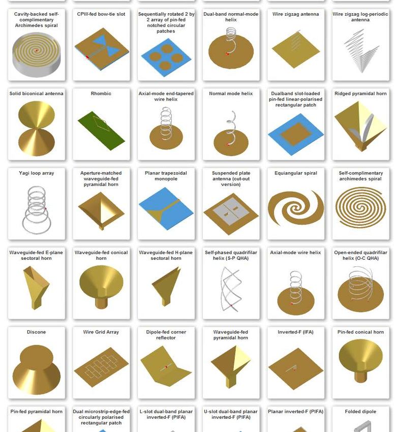
OUTLINE

   Introduction to 4G/LTE
   Antenna Design challenges
   Numerical Techniques
   Design & optimization of Antennas
    for Handset
   Handset with a head and SAR
    Calculations
   Handset & channel capacity
   Conclusion

                                        2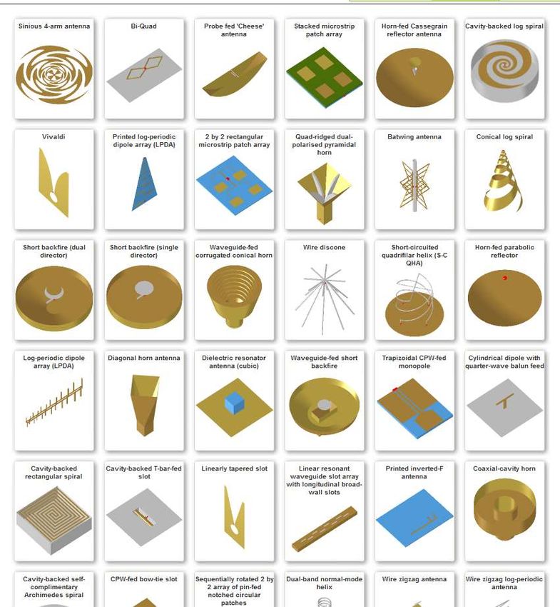
History of Mobile Phones

                                     Dr. Martin Cooper of
                                     Motorola, made the first US
                                     analogue mobile phone call on
                                     a larger prototype model in
                                     1973.
                                     This is a reenactment in 2007

© Motorola                                              Analog Motorola DynaTAC 8000X Advanced
                                                        Mobile Phone System mobile phone as of 1983

http://en.wikipedia.org/wiki/History_of_mobile_phones

                                                                                                      3
History of Mobile Phones

                                                1997-2003
http://en.wikipedia.org/wiki/History_of_mobile_phones

                                                            4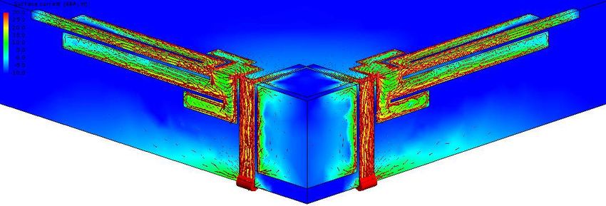
Smart Phones

                2003-2007

http://en.wikipedia.org/wiki/History_of_mobile_phones   2007-2011
                                                                    5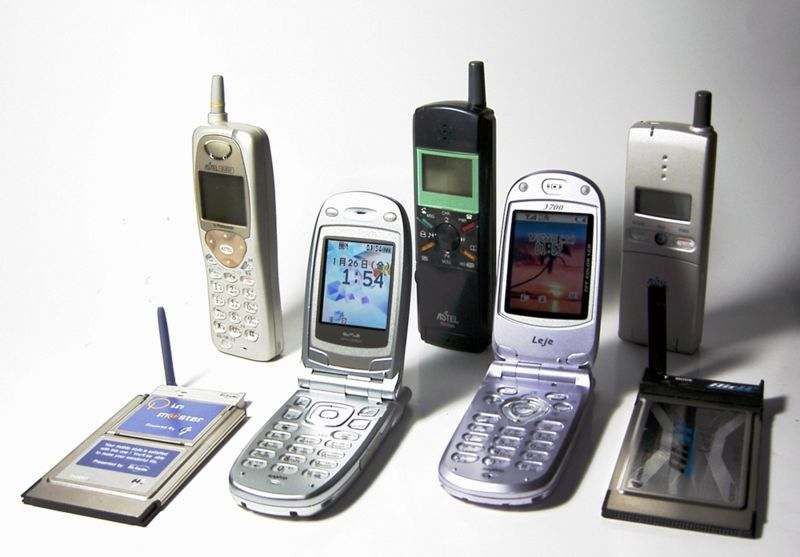
1G, 2G and 3G

In 1G, Narrow band analog wireless network is used, with this we can have
the voice calls and can send text messages.

Then in case of 2G Narrow Band Wireless Digital Network is used. Both
the 1G and 2G deals with voice calls and has to utilize the maximum
bandwidth as well as limited to sending messages i.e. SMS.

In 3G Wide Band Wireless Network is used with which the clarity
increases and gives the perfection as like that of a real conversation.
In addition to verbal communication it includes data services, access
to television/video, categorizing it into triple play service.
3G operates at 2100MHz and has a bandwidth of 15-20MHz.

                                                                            6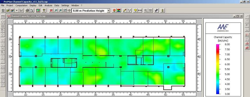
4G/LTE

• 4G is expected to provide a comprehensive and secure all-IP based mobile
  broadband solution to laptop computer wireless modems, smartphones, and
  other mobile devices.

• Facilities such as ultra-broadband Internet access, IP telephony, gaming
  services, and streamed multimedia may be provided to users.

• 4G technologies such as mobile WiMAX, HSPA+, and first-release Long
  term evolution (LTE) have been on the market.

•   Scalable channel bandwidth: 5 – 20 MHz (optionally up to 40 MHz)
    @ 2.6 GHz (for mobile applications)

•   Peak data rates:
     –   ~ 100 Mbit/s for high mobility communications
     –   ~ 1 Gbit/s for low mobility communications

                                                                             7
Antenna Design Challenges for 4G/LTE Handsets

• Antenna Size

• Mutual Coupling

• In-Situ Performance

• Compliance with SAR Regulation

• Channel Capacity Improvements using MIMO

          Peak data rates:
               ~ 100 Mbit/s for high mobility communications
               ~ 1 Gbit/s for low mobility communications

                                                               8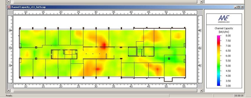
Computational Electromagnetics for
         Antenna Design and Optimization
            Meeting the Design Challenges
•   Numerical solution based on approximation of currents and/or
    fields
•   Desirable properties of CEM methods:
     – Approximation may be reduced in order to increase accuracy,
        approaching the analytical result
     – Computational cost (CPU time & memory) must be as low as
        possible

                                                                     9
Computational Electromagnetics for
          Antenna Design and Optimization

                             CEM tool

Computer modeling

               Discretized              Numerical analysis
                 Model

                                                             10
Comparison of Numerical Techniques
Field method Source method
Base Electromagnetic fields Currents and charges
Equations Differential equations Integral equations
Discretisation Volumetric Mesh (cubes, Surface Mesh (triangles,
tetrahedrals) quads)
Infinity of space Special ABC’s must be Exact treatment using
(open problem) introduced or use exact exact radiation boundary
radiation boundary condition condition
Methods Finite Difference methods (FD) Method of Moments (MoM)
Finite Element methods (FEM)
Commercial Codes HFSS, CST, FEKO, XFDTD, FEKO, WIPL-D
Empire, SEMCAD (IE3D, Sonnet, Designer
etc – 2D
113D EM Simulation Map
UTD
Electrical Size
Complexity of Materials
123D EM Simulation Map
• Due to their formulations (and
assumptions) CEM techniques
inherently have different
strengths and weaknesses.
• The specific problem dictates
which technique is most
Electrical Size
applicable.
Complexity of Materials
133D EM Simulation Map
There is no single solution for all
problems on the simulation map.
For the time being combined
solutions are required.
Electrical Size
Complexity of Materials
143D EM Simulation Map
UTD Asymptotic
Hybridization to
solve large and Methods
PO/GO complex
problems
(high-frequency
approximation)
MLFMM
Electrical Size
MOM
Full-wave
Methods
(physically
FEM rigorous
solution)
Complexity of Materials
15
15Antenna Design for 4G/LTE
Samsung Infuse
iPhone 4S Motorola Atrix
Thickness ~ 1cm
Length ~ 6cm
Motorola Droid BIONIC
16Electrically small antenna (ESA)
• An ESA is an antenna that satisfies the condition
ka < 0.5
‘k’ is the wave number 2π/λ
‘a’ is the radius of the minimum size sphere that encloses the antenna
Chu sphere is the minimum
circumscribing sphere enclosing
the antenna of maximum
dimension 2a
Frequency = 2.6GHz
ka ~ 0.5, length (2a) ~ 2cm
Wavelength = 11.5cm
John Leonidas Volakis, Chi-Chih Chen, and Kyōhei Fujimoto, Small antennas:
miniaturization techniques & applications. The McGraw-Hill Companies, New York,
NY, 2010
17Dual-Port Antenna
Antenna dimensions Fabricated Model
Qinjiang Rao and Dong Wang, “A Compact Dual-Port Diversity Antenna for Long-Term
Evolution Handheld Devices”, IEEE Transactions on Vehicular Technology, Vol. 59, No. 3,
March 2010
18Dual-Port Antenna
S-parameter results of the dual-port Thickness ~ 1cm
antenna
Thickness of current smart phones ~ 0.5cm
This antenna won’t go with current day slim handheld
devices for its size. We need an electrically small antenna (ESA)
Qinjiang Rao and Dong Wang, “A Compact Dual-Port Diversity Antenna for Long-Term Evolution Handheld Devices”, IEEE
Transactions on Vehicular Technology, Vol. 59, No. 3, March 2010
19Challenge - Isolation Techniques
• Placing the antennas half a wavelength apart as a rule
of thumb for low enough correlation
– Not attractive because of the space required for separation
• Orthogonally polarized elements offer significant port
isolation
– Finite-sized ground plane generates high cross-polar
components that spoil the polarization purity resulting in
high coupling
• Using branch line hybrid with passive inductors and
capacitors to decouple the antenna ports1
– Space required for the hybrid is a constraint
• Using a neutralization stub (or parasitic elements)
between the antennas to achieve isolation2
– Not attractive because of the space required for parasitic
elements
1. Rashid Ahmad Bhatti, Soongyu Yi, and Seong-Ook Park, “Compact Antenna Array With Port Decoupling for LTE-
Standardized Mobile Phones”, IEEE Antennas & Wireless Propagation Letters, Vol. 8, 2009
2. Ibra Dioum, Aliou Diallo, Cyril Luxey, and Sidi Mohamed Farsi, “Compact Dual-Band Monopole Antenna for LTE
Mobile Phones”, Antennas & Propagation Conference, 8-9 November 2010, Loughborough, UK
20Dual-Port Antenna - Advantages
• Two orthogonal radiating elements are
used to achieve pattern diversity
• There are no additional neutralization
stubs (or) hybrids used to provide
isolation
• The zero separation leads to size
reduction resulting in compact design
Qinjiang Rao and Dong Wang, “A Compact Dual-Port Diversity Antenna for
Long-Term Evolution Handheld Devices”, IEEE Transactions on Vehicular
Technology, Vol. 59, No. 3, March 2010
Dual port
inverted PIFA
21New Design - Dual-Port ESA
• To go with present day typical handset (115x60x10 mm),
we designed a dual-port ESA
• The symmetry in the novel design keeps the antenna
characteristics identical for both radiating elements
Port 1 Port 2
New Design
22Port-to-Port Isolation – Initial Design
• The novel feed design provides good port-to-port isolation
even though the ports are physically connected
• But,
We need an antenna with low correlation and good matching at
the same time
Therefore,
The design is optimized for matching
23Design and Optimization
• The dual port antenna design is optimized for
both matching and isolation at the desired
frequency of operation (2.6 GHz)
1 2
• The optimization algorithms, PSO and Simplex (Nelder-Mead) are
used in the process
– PSO (Particle Swarm Optimization) being a global optimization
algorithm requires many iterations to converge
– Simplex is a local optimizer whose convergence is much faster
compared to global optimizers
– The success rate of Simplex depends on the starting point
– As a trade off, PSO is ran for few iterations
– The optimum of PSO is given as a starting point for Simplex
24Initial and Optimum Designs at 2.6 GHz
Initial design
Optimized design
Substrate (FR4)
Thickness = 5 mm
Dielectric constant = 4.8
Loss tangent = 0.017
Max. length of the radiating element, 2a = 17.8 mm
Wave number, k = 2π/λ = 0.0545
ESA condition, ka = 0.0545*17.8/2 = 0.485 < 0.5
25Initial Vs. Optimum
The optimized design provides good matching as well as
better isolation at the desired frequency (2.6 GHz)
26Dual-Port ESA in a Handset
Side view
Bottom view of the
handset with
antenna positions
• The novel ESA with ka = 0.485 (< 0.5) goes
with the present day handsets occupying
minimal space
• The dual-port design also offers the
convenience of placing the antenna on the
corners for maximizing usable space
27S-Parameters over usable LTE Bandwidth
The optimized design provides good matching as well as
better isolation over the desired LTE bandwidth (maximum
of 40 MHz)
28Antenna Working Configurations
• The dual port antenna can be used in different configurations
– 1, 2 excited
– 1 excited, 2 terminated with a matched load
– 1 matched loaded, 2 open (high impedance)
1 2
• When both the ports are excited, it acts as a dual feed antenna
for MIMO applications
• In the second configuration, one antenna will be transmitter
while the other is a receiver
• In the third configuration, both can be used as receiving
antennas where you can switch between the ports based on
the incoming signal polarization and strength
29Surface Currents
Even though the two antennas are connected, there is a clear
voltage null between the two ports (isolation)
The phase of the two radiating element currents are in
opposite directions (polarization diversity)
30Radiation Patterns
Port 1 excited Port 1 excited
Port 2 open Port 2 short
Port 1 & Port 2 excited
31Handset & Head
32Dual Port ESA in Handset
Radiation pattern of the dual
port antenna integrated into a
mobile handset
At 2.6 GHz LTE frequency
33Handset with Head
Radiation pattern of the
handset when placed
close to a head
At 2.6 GHz LTE
frequency
34Specific Absorption Rate
35Specific Absorption Rate (SAR)
σ is the electrical conductivity
E is the RMS electric field
ρ is the mass density
Units: Watts per kilogram (W/kg)
Average absorption of RF energy over a volume
(the Volume-average SAR)
or
the maximum absorption in a 1 g or 10 g cube anywhere in a
given volume
(the Spatial-peak SAR)
36FCC regulations for SAR
• Working closely with federal health and safety agencies, the FCC has
adopted limits for safe exposure to radio frequency (RF) energy
• The FCC requires cell phone manufacturers to ensure that their
phones comply with these objective limits for safe exposure
• For Europe, the current limit is 2 W/kg for 10-g volume averaged
SAR
• For the United States and a number of other countries, the limit is
1.6 W/kg for 1-g volume-averaged SAR
– The lower U.S. limit is more stringent because it is volume-averaged over
a smaller amount of tissue
37SAR of 4G/LTE Handset
The volume averages SAR of 1 g cube (US standard) is
0.000365843 W/kg
The volume averages SAR of 10 g cube (European standard)
is 0.000260617 W/kg
38SAR of Popular Handsets
Phone SAR (W/kg)
Apple iPhone 3G 0.878
Apple iPhone 3GS 1.100
Apple iPhone 4 0.930
Apple iPhone 4S 0.988
Samsung GT-i9000 Galaxy 0.268
Samsung GT-i9100 Galaxy SII 0.338
HTC Desire S 0.353
Sony Ericsson Xperia PLAY 0.360
Nokia 6700 Classic 0.410
The FCC limit for public exposure from cellular telephones is
an SAR level of 1.6 watts per kilogram (1.6 W/kg)
http://www.sardatabase.com/
39Channel Capacity
40MIMO
• LTE standard allows multiple antennas on both ends of the wireless
channel to support high data rate applications
• MIMO technologies have been widely used in LTE to improve downlink
peak rate, cell coverage, as well as average cell throughput
Base station Mobile terminal
Tx 1 Rx 1
Tx 2 Rx 2
Signal
Separator
Tx 3 Rx 3
Tx 4 Rx 4
Transmission
Channel
LTE MIMO Concept
41MIMO Configurations
2x2 MIMO 4x2 MIMO
Configuration Configuration
Top view of the handset
42Channel Matrix
• MIMO channel matrix describes the radio channel
between each transmit and each receive antenna of the
system
• Between every transmit antenna m and every receive
antenna n of a MIMO system, the complex single-input-
single-output (SISO) channel impulse response of
length L+1
• The linear time-variant MIMO channel is represented by
the channel matrix with dimension NR × NT
43Channel Capacity
• Channel capacity can be calculated from the ‘channel
matrices’ obtained from measurements
• Alternatively,
– The channel capacity is computed by post processing the
ray data from a fixed transmitter in a certain environment
(channel) for different positions of the receiver
• The channel capacity is computed as;
where,
‘HF’ is the channel matrix
‘ρ’ is the SNR
44Indoor Environment
Commercial software ‘WinProp’ from AWE Communications
is used to calculate the ‘channel capacity’
www.awe-communications.com
45Channel Capacity in Indoor Environment
2x2 MIMO system
(antennas on bottom 2
corners of the handset)
4x2 MIMO system
(antennas on 4 corners
of the handset)
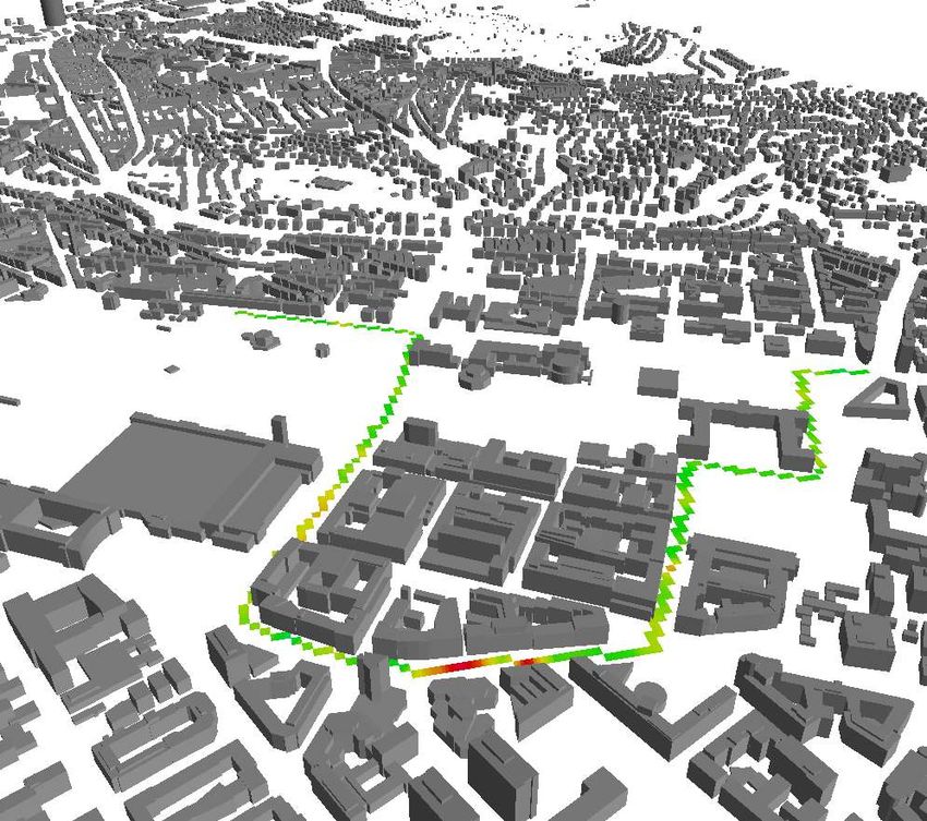
46Channel Capacity in Urban Environment
Simulation along
a trajectory in an
urban area
Using 4 antenna
elements on
4 corners as a 4x2
MIMO system
47Conclusion
• Challenges in designing an antenna for a LTE-MIMO system
are discussed
• A novel dual port antenna for LTE-MIMO applications is
introduced
• The performance of the antenna in a handset when placed
close to a human head is analyzed from the radiation pattern
• The channel capacity of the novel antenna in a handset is
computed in both indoor and urban environments
48Questions ??
49Version 3.3
50Design Parameters
Frequency,
Gain, Initial Geometry
VSWR
EM Analysis
Optimization
Modification of
Final Geometry Geometry
51Design Parameters
Frequency,
Gain,
VSWR
Final Geometry
FEKO – www.feko.info
Antenna Magus - http://www.feko.info/product-detail/antenna-magus
52Extensive Antenna Database
More than 150 Antennas
53More complex, very useful
additions
Diagonal horn
Sinuous antenna
Microstrip fed Vivaldi
Notched trapezoidal
Printed self-phased
monopole
quadrifilar helixEngineering utilities
Tools Transitions Libraries
Array synthesis
• Substrates
• Waveguides
Friis transmission equation
Radar range equation
Gain/Beamwidth Converter
Gain from a given Aperture
Charting ToolEvaluation
Free Evaluation Version can be downloaded from
www.feko.info/download
56http://www.feko.info/product-detail/antenna-magus
57You can also read