Audible acoustics from low magnitude fluid induced earthquakes in Finland - Nature
←
→
Page content transcription
If your browser does not render page correctly, please read the page content below
www.nature.com/scientificreports
OPEN Audible acoustics
from low‑magnitude fluid‑induced
earthquakes in Finland
Oliver D. Lamb1*, Jonathan M. Lees1, Peter E. Malin2,3 & Tero Saarno4
Earthquakes are frequently accompanied by public reports of audible low-frequency noises. In
2018, public reports of booms or thunder-like noises were linked to induced earthquakes during
an Engineered Geothermal System project in the Helsinki Metropolitan area. In response, two
microphone arrays were deployed to record and study these acoustic signals while stimulation at the
drill site continued. During the 11 day deployment, we find 39 earthquakes accompanied by possible
atmospheric acoustic signals. Moment magnitudes of these events ranged from −0.07 to 1.87 with
located depths of 4.8–6.5 km. Analysis of the largest event revealed a broadband frequency content,
including in the audible range, and high apparent velocities across the arrays. We conclude that the
audible noises were generated by local ground reverberation during the arrival of seismic body waves.
The inclusion of acoustic monitoring at future geothermal development projects will be beneficial for
studying seismic-to-acoustic coupling during sequences of induced earthquakes.
Earthquakes of a wide range of magnitudes are commonly accompanied by reports and/or measurements of
atmospheric acoustic waves at various epicentral distances. These waves may have frequencies ranging from
infrasonic (< 20 Hz ) up to and beyond the minimum limit of human hearing ability (20–70 Hz). Cases of the
latter have been described as low rumbling sounds or b ooms1, and have been reported for shallow (< 2 km )
earthquakes in the U SA2 and F
rance3–5. The event magnitudes associated with these sounds have been stated to
be as low as −2 and −0.7, respectively. Audible noises are also frequently publicly reported for larger magnitude
earthquakes, and accompanied by the frequent detection of infrasonic acoustic waves at large distances (up
to 5300 km)6–16. Mapping of acoustic sources during and immediately after earthquakes has identified three
sources of earthquake acoustic signals17: (1) ‘epicentral’ (i.e. seismic-to-acoustic coupling directly above or near
the earthquake epicentre)7,8, (2) ‘local’ (i.e. generated by the passage of seismic waves near sensor located away
from the epicentre)6,18,19 and (3) ‘secondary’ (i.e. generated by interaction of seismic waves with topographic
features)8,11,20,21. Efficient coupling of seismo-acoustic energy into the atmosphere has been attributed to three
parts of the wavefield s pectrum22,23: vertically propagating homogenous body waves (particularly P- and SV-
waves)24, inhomogeneous body waves (a.k.a. evanescent waves)25, and surface waves, or more specifically, leaky
Rayleigh or Stonely waves26. Seismo-acoustic recordings of earthquake acoustic signals (audible and infrasonic)
at near (< 25 km) or epicentral distances are limited to only a few studies4,21,24. Here we describe a case study of
local acoustic waves generated by earthquakes during a hydraulic stimulation project in Finland, one of the first
documented recordings of acoustic signals from an induced earthquake sequence and are amongst the lowest
magnitude events to be recorded.
St1 Deep Heat Oy venture
The Engineered Geothermal System (EGS) pilot project, operated by the St1 Deep Heat Oy energy company, was
located in the Helsinki Metropolitan area within the campus of Aalto University (Fig. 1). The aim of the project
was to develop an EGS facility in order to produce a sustainable baseload for the local district heating system27.
In 2018, a 6.1 km deep stimulation well was drilled into crystalline Precambrian Svecofennian basement rocks
consisting of granites, pegmatites, gneisses, and a mphibolites27. This bedrock features extensive faults, lineaments,
and fractures28 and is only locally covered by a thin (< 10 m) layer of glacial till or s oil29. From 4 June to 22 July
2018, a total of 18,160 m3 of water was pumped into the stimulation well at depths of 5.7–6.1 km; this included
moving injection intervals and multiple stoppages for a few days27,29. Induced seismicity was monitored by an
1
Department of Geological Sciences, University of North Carolina at Chapel Hill, Chapel Hill, NC, USA. 2Earth
and Ocean Sciences, Nicholas School of the Environment, Duke University, Durham, NC, USA. 3ASIR Advanced
Seismic Instrumentation and Research, Raleigh, NC, USA. 4St1 Deep Heat Oy, Helsinki, Finland. *email: olamb@
email.unc.edu
Scientific Reports | (2021) 11:19206 | https://doi.org/10.1038/s41598-021-98701-6 1
Vol.:(0123456789)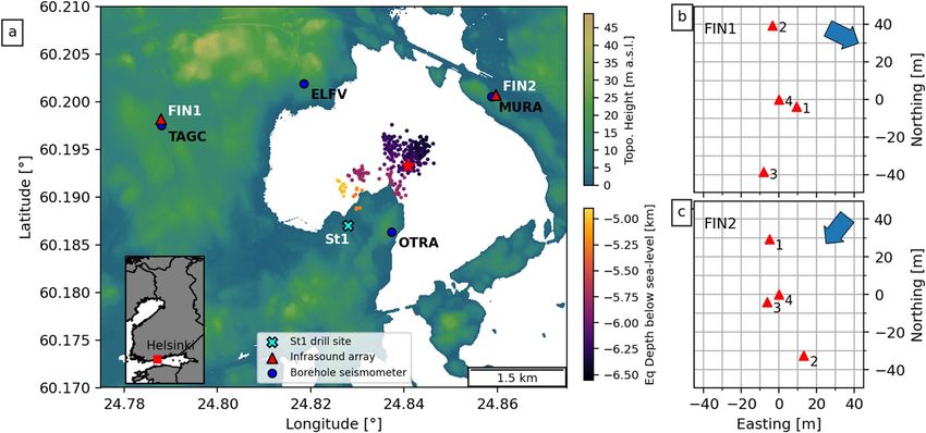
www.nature.com/scientificreports/
Figure 1. (a) Topographic map of the region around the St1 drill site (cyan cross) showing locations and
names of borehole seismic stations (blue circles) and temporary acoustic arrays (red triangles). Also plotted
are locations of earthquakes recorded during the acoustic deployment, colored by depth. Red star indicates
the location of the Mw 1.87 event. Inset: Map of Finland showing location of the Helsinki Metropolitan area.
Panels (b,c) show the infrasound sensor distribution for arrays FIN1 and FIN2, respectively, with back azimuth
direction to the ST1 drill site indicated by the blue arrow. Topographic data used in panel (a) were downloaded
from the National Land Survey of Finland via the Open data file download service (last accessed December
2020). This figure was generated using Matplotlib (v. 3.2.2; matplotlib.org)31 and Cartopy (v. 0.17.0; scitools.org.
uk/cartopy)32.
extensive seismic network, including 3-component borehole seismometers installed in 0.3–1.15 km deep wells
at distances up to 8.2 km from the drill site (Fig. 1). The purpose of the seismic network was to provide accurate
hypocenter locations and magnitudes of induced earthquakes for both industrial and regulatory purposes (i.e.
Traffic Light System)27,30.
From 4 June to 1 August 2018, a total of 8412 earthquakes were automatically recorded by the network out
of which 1977 were suitable for relocations and magnitude c alculations27. These events were located across three
distinct clusters ranging in depths of 4.8–6.6 km and moment magnitudes ( Mw ) of −0.76 to 1.87 (Fig. S1 in
Supporting Information). Fault plane solutions for a set of selected events indicated reverse faulting along pre-
existing fractures associated with NW–SE trending fault zones reactivated by the hydraulic i njection29,33. Propa-
gation directions of SH waves across local seismic arrays show deviations from the earthquake back azimuths
that may be related to the local heterogeneous seismic s tructure34. The Institute of Seismology at the University
of Helsinki (ISUH) collected 220 public reports of felt earthquakes, which unexpectedly also included dozens of
audible disturbances, typically described as thunder- or blast-like29,30. The largest and most reported event was
a Mw 1.87 event on 8 July 2018 located at 6.3 km depth (Fig. 1). This event generated 78 public reports and was
apparently heard up to 9 km away from the epicentre29. Notably, spatial distributions of the reports were strongly
correlated with the SH radiation pattern of the reverse faulting mechanism in the event29.
Data and methods
In response to the reports of audible earthquake events, we deployed two temporary arrays of infrasound micro-
phones in the area from 7 to 18 July to study the nature of these atmospheric acoustic signals. The arrays were
deployed at distances of ∼ 2.5 and ∼ 2.2 km from the St1 drill site. Each deployment consisted of three micro-
phones extended on cables up to 35 m from a central data recorder, where a fourth microphone was located
(Fig. 1b,c). The data recorder was a REFTEK RT 130 data logger which provided a 24-bit, GPS-time synchronized
recording set to 100 samples per second, resulting in an anti-aliasing Finite Impulse Response (FIR) filter cut
off of 40 Hz. The microphones were identical InfraBSU (vers1) microphones, which incorporate a MEMS sen-
sor and capillary filters to provide a flat response from 0.1 up to > 40 Hz35. To aid analysis and interpretation of
acoustic data in this study, we also included seismic data from borehole seismometers located near each array
(TAGC and MURA; Fig. 1a). Each seismometer was composed of a three-component Sunfull PSH geophone
sensor ( fN = 4.5 Hz ) recording at 500 samples per second and located ∼ 1.15 km below the surface (for more
information, see Kwiatek et al.27).
For this study, all data were filtered with a 2 Hz high-pass Butterworth filter to reduce continuous background
noise (unless otherwise indicated). Data were manually inspected for consistent arrivals across at least two
microphones in each array to assess if earthquake-generated atmospheric acoustic waves were detected following
Scientific Reports | (2021) 11:19206 | https://doi.org/10.1038/s41598-021-98701-6 2
Vol:.(1234567890)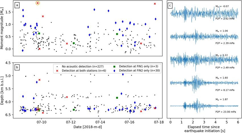
www.nature.com/scientificreports/
Figure 2. Moment magnitudes (a) and depths (b) of the 266 relocated seismic events recorded during the
infrasound array deployment near the St1 Deep Heat Oy EGS project. Red ‘x’, green squares, and blue diamonds
indicate the events which were detected by both acoustic arrays, only at FIN1, or only at FIN2, respectively.
Orange circle in each panel indicates the Mw 1.87 event described in detail in Figs. 3 and 4. (c) 6 s of normalised
acoustic data (highpass filtered at 5 Hz) recorded by sensor 2 at FIN2 after the initiation of five example
earthquakes, including the lowest and highest magnitude events. Calculated Mw and recorded peak-to-peak
pressure amplitudes (P2P) of each event is indicated on the right; each event was located at 6.2–6.3 km depth
(see Figs. S2 to S11 in Supporting Information for waveforms and frequency spectrograms from all microphones
for each event).
an induced earthquake. To estimate the arrival times for different body wave phases at each array, we use P- and
S-wave velocities of 6.25 and 3.75 km s−1 respectively, as estimated from borehole logs at the St1 drill site (see
supplementary materials in Kwiatek et al.27). One of the key advantages of deploying acoustic microphones in
an array configuration is it permits the calculation of back azimuth direction and apparent velocities of acoustic
waves propagating across the deployment. Back azimuth is calculated using least-squares beamforming where
time delays between sensors are calculated using cross-correlation36. Here we estimated back azimuths and appar-
ent velocity values for 0.5 s windows with 90% overlap within the first 3 s after the initiation time of the earth-
quake. Windows in which calculated apparent velocity were below physically possible values (i.e. < 0.25 km s−1)
or relative power was lower than 0.6 were discarded. Relative power is defined as the signal power of the mean
waveform for minimum apparent velocity divided by average element power in the same time window. We find
that waveforms tend to lack coherency between sensors, therefore we used waveform envelopes, determined from
the square root of the Hilbert Transform, which were then smoothed using the average of an 8 sample moving
window (Fig. 4a,b). All analysis presented here was carried out within the ObsPy python p ackage37.
Observations
During 7–18 July, 266 earthquakes were detected and relocated within a few hundred metres of the stimulation
interval. These events occurred at depths of 4.8–6.5 km below sea level and had moment magnitudes ranging
from −0.19 to 1.87 (Figs. 1a, 2a,b). Through manual inspection of the acoustic data, 39 of the 266 earthquakes
were followed shortly by possible atmospheric disturbances across at least one array that may be interpreted as
earthquake associated acoustic waves (Fig. 2). Atmospheric disturbances were more commonly seen at FIN2
(n = 36) than FIN1 (n = 9), with only 3 events seen exclusively at the latter. The smallest event was a Mw −0.07
on 8 July, and the largest was the widely heard Mw 1.87 on the same day (Fig. 2c). As the latter earthquake
produced the highest signal-to-noise ratios at both microphone arrays, the remainder of this section will focus
on the analysis of acoustic data from this particular event. Similar analysis as below has been conducted on the
other four example events in Fig. 2c and detailed in Figs. S12 to S15 in Supporting Information. We find that
the acoustics recorded shortly after the Mw 1.87 contain the only waveforms that can be confidently attributed
to the earthquake due to the back azimuth and apparent velocity calculations.
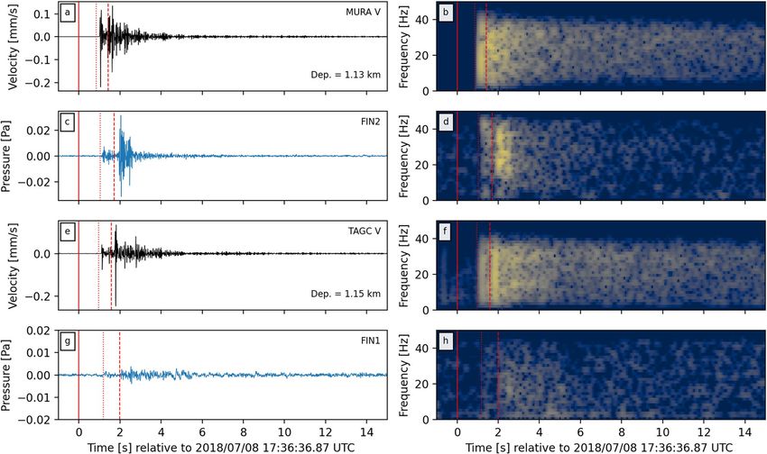
For the Mw 1.87 event the acoustic data recorded at FIN2 have peak amplitudes an order of magnitude larger
than those recorded at FIN1 (Fig. 3c,g). Frequency spectra highlight the broadband nature of the atmospheric
acoustic signals, with frequencies ranging from 2 to 40 Hz (Fig. 3d,h), which are the limits set by the filter and
Scientific Reports | (2021) 11:19206 | https://doi.org/10.1038/s41598-021-98701-6 3
Vol.:(0123456789)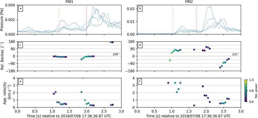
www.nature.com/scientificreports/

                                            Figure 3.  Filtered waveforms (left column) and their respective frequency spectrograms (right column) of the
                                            Mw1.87 event as recorded by seismic station MURA (a,b), acoustic array FIN2 (c,d), seismic station TAGC (e,f)
                                            and acoustic array FIN1 (g,h). Note that the seismic waveforms are from the vertical component of the station.
                                            Spectrograms were calculated with 0.5 s windows with 90% overlap. Also plotted is the time of the event (solid
                                            red line), as well as predicted arrival times for P- and S-wave phases (dotted and dashed red lines, respectively)
                                            from source locations to each station or array.

                                            Figure 4.  Beamforming results for arrays FIN1 (left column) and FIN2 (right column) for the first 3 seconds
                                            after the Mw1.87 event. (a,b) Smoothed waveform envelopes from each element in each array. Dotted and
                                            dashed lines plot the estimated arrival times of P- and S-waves, respectively (from epicentre to array). (c,d) Back
                                            azimuth calculations for 0.5 s moving windows with 90% overlap, relative to the theoretical back azimuth from
                                            array to the Mw1.87 event epicentre (horizontal dotted red line, absolute back azimuth value labeled on right
                                            hand side). (e,f) Calculated apparent velocity values across each array for each 0.5 s window. Points in panels
                                            (c–f) are colored by relative power, where lighter colors indicate higher relative power.

          Scientific Reports |   (2021) 11:19206 |               https://doi.org/10.1038/s41598-021-98701-6                                                   4

Vol:.(1234567890)
www.nature.com/scientificreports/
sampling rates (see Data and Methods section). The acoustic waves and their spectra at each array appear to
show distinct multi-phase arrivals that correlate with seismic waves recorded at the nearby borehole seismom-
eters (Fig. 3a,b,e,f). The different arrival phases at each array appear to be coincident with the predicted arrivals
of P- and S-waves (dotted and dashed red lines in Fig. 3). The highest acoustic amplitudes are correlated with
the arrival of the S-waves at each array with time offsets between acoustic and seismic arrivals correlating with
depths of seismic stations (noted in panels a and e of Fig. 3). Calculated values of back azimuth and apparent
velocities at or near the estimated time of arrivals for P- and S-waves (red lines in Fig. 4a,b) indicate arrivals
from the direction of the Mw 1.87 event epicentre (Fig. 4c,d). Apparent velocity values at these times indicate
relatively initially high propagations across the array, which rapidly decrease to lower values in the subsequent
time windows (Fig. 4e,f). For comparison, similar analysis was conducted on a Mw 1.84 event that occurred
on July 16. Despite clear waveforms arriving at each array (Figs. S12, S13 in Supporting Information), the back
azimuth and apparent velocities across the arrays did not correlate with expected values from the event (Fig. S18
in Supporting Information).
Discussion
Here we have presented evidence for infrasonic and audible atmospheric acoustic signals generated by at least
one low magnitude fluid-induced earthquake. These observations are notable for two reasons: (1) these are the
first recorded earthquake-generated acoustic signals from induced earthquakes, and (2) they represent the lowest
magnitude events to be recorded by acoustic microphones. (There are reports of audible noises from earthquakes
with magnitudes as low as −2 but these events were not recorded with microphones5.) Manual inspection of data
identified at least 39 events where possible acoustic waves were recorded propagating across at least one array of
sensors (Fig. 2). This represents only 15% of all earthquakes relocated during the deployment, but the location of
the arrays within a large metropolitan area with a large number of low-frequency noise sources may have acted to
reduce this proportion. On the other hand, the potential for false associations due to coincidental sound arrivals
from anthropogenic sources would suggest this 15% value may be an overestimate. Further analysis of the wave-
forms across each array finds that only the acoustics shortly after largest earthquake can be reasonably attributed
as having derived from the seismic event. The acoustic waves contained broadband frequency ranges from 2 up
to 40 Hz, and possibly higher but is limited by the anti-alias FIR filter of the sample recording rate (Fig. 3d,h).
This broadband frequency is often but not always observed for other possible acoustic signals from earthquakes
(Figs. S2–S13 in Supporting Information) and this is most likely due to low signal-to-noise ratios. Nevertheless,
this frequency range overlaps with the lower range of human hearing (down to 20 Hz), therefore supporting
the notion that thunder- or blast-like sounds heard by the public were generated by the e arthquakes29,30. These
frequency ranges also match previously reported values from audible natural e arthquakes4,24.
Given that the infrasound sensors are typically placed in direct contact with the ground surface during
deployments, contamination of recorded infrasound signals by physical shaking of the sensor could be a concern.
However, testing of the seismic response of various acoustic sensors have consistently concluded that physi-
cal vibration does not significantly influence the recorded infrasound signals4,24,38. The MEMS-based micro-
phones used in this study (InfraBSU vers1) have low inertial mass and are similar in design to the MEMS-based
transducers described in Marcillo et al.35. These sensors were found to have minimal seismic-to-noise coupling
during calibration studies at the Facility for Acceptance, Calibration and Testing site at the Sandia National
Laboratories21. Therefore, we do not consider direct seismic shaking of the sensor to be of importance in the
acoustic signals presented here.
During the expected arrival times of the P- and S-waves for the Mw1.87 event at each array, the back azimuth
values align at or around the direction of the earthquake epicentre (Fig. 4c,d). It is notable that a significant
number of windows were discarded due to unrealistic apparent velocity values or low relative power. Further-
more, similar calculations for acoustic waveforms from other events produced poor or inconclusive results
(Fig. S14–S18 in Supporting Information). This is likely due to low signal-to-noise ratios, the low sampling
rates chosen (100 samples per second), poor array-perpendicular apparent velocity resolution due to the narrow
deployment configuration of the arrays, or technical issues with individual sensors. Ideally, 3 or 4 microphone
sensor arrays would be arranged as an equilateral triangle. However, the geometry of each array here was forced
by the limited availability of deployment areas which is to be expected for a rapid response deployment in an
urban environment. Nevertheless, azimuthal resolution is expected to be good and poor for bearings perpen-
dicular and parallel to the arrays, respectively. Calculated infrasound array uncertainties following the method
of Szuberla and O lson39 indicate a minimum uncertainty for back azimuth of 10◦ for each array given a 95%
confidence interval (Figs. S19, S20 in Supporting Information). The consistent deviation between calculated back
azimuths and great-circle direction to the earthquake epicentre at FIN2 (Fig. 4d) may be related to either: (1) the
non-optimal array configuration or (2) the locally heterogeneous seismic structure28. The latter was inferred to
explain similar deviations at local seismic arrays deployed in the same region during the same induced seismic
sequence34.
A common observation in previous earthquake acoustic studies is the presence of ‘local’ infrasound at the
sensor location6,18,19, as well as ‘secondary infrasound’ generated away from the earthquake epicentre8,10,11,17,20,21.
Calculated apparent velocity values during the arrival of seismic waves from the Mw 1.87 event begin with rela-
tively high propagation velocities across the array, but rapidly decrease to lower values (Fig. 4e,f). The initially
high velocities (> 1 km s−1) suggest the presence of ‘local’ infrasound generated during the passage of seismic
waves across the array, but could also indicate near-vertical wave arrival directions at the array. Considering the
ratio between earthquake depths (4.8–6.5 km) and epicentre-array distances (< 2.5 km), it is reasonable to expect
near vertical arrival angles of seismic waves at each array. The relationship between vertical ground motion to
air pressure has been formulated as �P = ρcv where ρ is the density of air (1.225 kg m−3), c is the velocity of
Scientific Reports | (2021) 11:19206 | https://doi.org/10.1038/s41598-021-98701-6 5
Vol.:(0123456789)www.nature.com/scientificreports/
sound in the air (330 m s−1), v is the vertical ground velocity, and P is the measured pressure fluctuation6,18,19.
At station MURA, the peak vertical velocity during the P-wave arrival was 0.2 mm s−1 which, according to the
above equation, should correspond to a 0.08 Pa acoustic pressure wave. This significantly overestimates what
was measured at the surface at station FIN2 during the arrival of P-waves (< 0.01 Pa ; Fig. 3). This may be due
to attenuation of the seismic waves between MURA (at 1.13 km depth) and the surface, unquantified local site
effects at each station, or this back-of-the-envelope calculation is too simplistic to quantify local seismic-to-
acoustic coupling for low magnitude events.
The lower propagation velocities are of the same magnitude as atmospheric acoustic waves (∼ 330 m s−1).
This can be interpreted as ‘secondary infrasound’ from sources in close proximity to the arrays (< 150 m), within
the same back azimuth from source to receiver. These acoustic signals are confirmed to be caused by the inter-
action of surface waves with topography or other significant crustal features11,17. Considering the lack of steep
topographical features around the St1 drill site (Fig. 1a), it’s possible the secondary acoustic signals were instead
generated by mechanical shaking of buildings or other structures (e.g. bridges) near each array. However, it is
worth noting that velocity resolution perpendicular to the arrays is poor due to the forced narrow deployment
configuration (Figs. S16, S17 in Supporting Information).
‘Epicentral’ infrasound is not considered a significant source of acoustics during these earthquakes due to
the epicentre-station distances. For example, the epicentre of the Mw1.87 event was 4.1 and 1.3 km from FIN1
and FIN2, respectively. Assuming an atmospheric acoustic velocity of 330 m s−1, we would estimate an arrival
time of approximately 12.4 and 3.9 s for ‘epicentral’ infrasound at FIN1 and FIN2. No clear arrival signals at
these times are seen in the recorded waveforms (Fig. 3c,g). Furthermore, the epicentres have been located at
4.8–6.5 km depth beneath a shallow lagoon (Fig. 1a). Theoretical studies have shown that acoustic radiation into
the atmosphere at water-gas or solid-gas interfaces may only be detectable when the earthquake is located at a
depth on the order of the wavelength or less22,25. Therefore, the atmospheric acoustic signals recorded during
the largest earthquake, and all other recorded events, were likely generated by ground motion at and near the
station during and immediately after the arrival of P- and S-waves at the ground surface within close proximity
of the microphone arrays. In other words, we record both ‘local’ and ‘secondary’ infrasound during the passage
of seismic waves across the microphone arrays during the sequence of induced earthquakes.
A notable observation from the public reports compiled during the induced earthquake sequence is the
geographical distribution of disturbances correlated with the radiation patterns of S-waves (see Fig. 5 in Hillers
et al.29). The FIN2 acoustic array was located adjacent to the area with the greatest number of reports. This pat-
tern correlates with the amplitude difference between the acoustic waves recorded at FIN1 and FIN2 for the Mw
1.87 event, with amplitudes an order of magnitude higher at the latter than the former (Fig. 3c,d). Furthermore,
a higher number of apparent earthquake-generated acoustic waves were recorded at FIN2 (N = 36) than at FIN1
(N = 9). Another factor to consider is that the FIN1 array was deployed on the margin of an active golf course
which was built on top of a former municipal waste landfill, while FIN2 was deployed within a small forested
locality near an area where buildings are frequently constructed directly onto outcropping bedrock. This suggests
that the presence of a soft sedimentary layer above the bedrock may act as a dampener during seismic-to-acoustic
coupling of body waves. Previous observations have suggested that low frequency (< 10 Hz ) signals in the coda
of acoustic waves may be generated by Rayleigh waves in a thin (< 100 m) sedimentary layer above the bedrock4.
No such low frequency coda is evident in the recordings seen here (Fig. 3d,h). This also contradicts observations
from fast field program modeling at the ground-atmosphere interface that suggested enhanced seismo-acoustic
coupling due to the presence of a sedimentary layer23. The observations described here suggests further work
may be needed to test for seismo-acoustic coupling effects during a range of various sedimentary layer properties
(e.g. thicknesses, small versus large basins, poorly consolidated versus well consolidated sediment). Nevertheless,
the correlation between public sound report distributions and the acoustic amplitudes highlights the potential
utility of such reports for monitoring at future EGS projects, particularly when high-quality geophysical record-
ings may not be available.
Conclusions
Acoustic monitoring can help explain human observations and may also provide quantitative insights into the
mechanics of ground motions responsible for generating earthquake sounds. Here we have presented acoustic
events recorded within the Helsinki Metropolitan area in July 2018 during hydraulic stimulation at a pilot Engi-
neered Geothermal System project. Based on the estimated timing of body wave arrivals, frequency content of
the waveforms, as well as estimated apparent velocity calculations, we have interpreted these acoustic events
as possibly being generated by reverberation of the ground surface during the arrival of P- and S-waves from
induced low magnitude earthquakes. Although only a minor proportion of induced earthquakes generated
recognizable acoustic waves, events with moment magnitudes ranging from −0.07 to 1.87 were recorded with
acoustic microphones at the surface. Of these, only the largest event could be confidently attributed as having
generated acoustic waves during the passage of seismic waves at each array. These events likely represent the first
documented atmospheric acoustics of induced earthquakes and are amongst the lowest magnitude seismic events
to be recorded with acoustic microphones. Given that Traffic Light Systems are increasingly being implemented
to reduce the potential seismic hazard due to induced s eismicity30, and the considerable public interest generated
by audible earthquakes in the Helsinki Metropolitan area29,30, future projects for developing geothermal systems
can benefit from deploying acoustic sensors to provide more detailed information in responses to public concern.
Received: 29 March 2021; Accepted: 6 September 2021
Scientific Reports | (2021) 11:19206 | https://doi.org/10.1038/s41598-021-98701-6 6
Vol:.(1234567890)www.nature.com/scientificreports/
References
1. Michael, A. J. Earthquake sounds. In Encyclopedia of Earth Sciences Series 1–5 (Springer, 2019).
2. Ebel, J. E., Vudler, V. & Celata, M. The 1981 microearthquake swarm near Moodus, Connecticut. Geophys. Res. Lett. 9, 397–400.
https://doi.org/10.1029/GL009i004p00397 (1982).
3. Sylvander, M. & Mogos, D. G. The sounds of small earthquakes: Quantitative results from a study of regional macroseismic bul-
letins. Bull. Seismol. Soc. Am. 95, 1510–1515. https://doi.org/10.1785/0120040197 (2005).
4. Sylvander, M., Ponsolles, C., Benahmed, S. & Fels, J. F. Seismoacoustic recordings of small earthquakes in the Pyrenees: Experi-
mental results. Bull. Seismol. Soc. Am. 97, 294–304. https://doi.org/10.1785/0120060009 (2007).
5. Thouvenot, F., Jenatton, L. & Gratier, J.-P. 200-m-deep earthquake swarm in Tricastin (lower Rhône Valley, France) accounts for
noisy seismicity over past centuries. Terra Nova 21, 203–210. https://doi.org/10.1111/j.1365-3121.2009.00875.x (2009).
6. Donn, W. L. & Posmentier, E. S. Ground-coupled air waves from the Great Alaskan Earthquake. J. Geophys. Res. 69, 5357–5361.
https://doi.org/10.1029/JZ069i024p05357 (1964).
7. Mikumo, T. Atmospheric pressure waves and tectonic deformation associated with the Alaskan earthquake of March 28, 1964. J.
Geophys. Res. 73, 2009–2025. https://doi.org/10.1029/JB073i006p02009 (1968).
8. Young, J. & Greene, G. Anomalous infrasound generated by the Alaskan earthquake of 28 March 1964. J. Acoust. Soc. Am. 71,
334–339. https://doi.org/10.1121/1.387457 (1982).
9. Olson, J. V., Wilson, C. R. & Hansen, R. A. Infrasound associated with the Denali fault earthquake, Alaska. Geophys. Res. Lett.
https://doi.org/10.1029/2003GL018568 (2002).
10. Le Pichon, A., Guilbert, J., Vallée, M., Dessa, J. X. & Ulziibat, M. Infrasonic imaging of the Kunlun Mountains for the great 2001
China earthquake. Geophys. Res. Lett.https://doi.org/10.1029/2003GL017581 (2003).
11. Mutschlecner, J. P. & Whitaker, R. W. Infrasound from earthquakes. J. Geophys. Res. 110, 1–11. https://d oi.o
rg/1 0.1 029/2 004JD
0050
67 (2005).
12. Le Pichon, A., Mialle, P., Guilbert, J. & Vergoz, J. Multistation infrasonic observations of the Chilean earthquake of 2005 June 13.
Geophys. J. Int. 167, 838–844. https://doi.org/10.1111/j.1365-246X.2006.03190.x (2006).
13. Arrowsmith, S. J. et al. A seismoacoustic study of the 2011 January 3 Circleville earthquake. Geophys. J. Int. 189, 1148–1158. https://
doi.org/10.1111/j.1365-246X.2012.05420.x (2012).
14. Evers, L. G. et al. Evanescent wave coupling in a geophysical system: Airborne acoustic signals from the Mw 8.1 Macquarie Ridge
earthquake. Geophys. Res. Lett. 41, 1644–1650. https://doi.org/10.1002/2013GL058801 (2014).
15. Pilger, C. et al. Infrasound and seismoacoustic signatures of the 28 September 2018 Sulawesi super-shear earthquake. Nat. Hazard.
19, 2811–2825. https://doi.org/10.5194/nhess-19-2811-2019 (2019).
16. Shani-Kadmiel, S., Averbuch, G., Smets, P., Assink, J. & Evers, L. The 2010 Haiti earthquake revisited: An acoustic intensity map
from remote atmospheric infrasound observations. Earth Planet. Sci. Lett. 560, 1–11. https://doi.org/10.1016/j.epsl.2021.116795
(2021).
17. Arrowsmith, S. J., Johnson, J. B., Drob, D. P. & Hedlin, M. A. The seismoacoustic wavefield: A new paradigm in studying geophysi-
cal phenomena. Rev. Geophys. 48, 1–23. https://doi.org/10.1029/2010RG000335 (2010).
18. Cook, R. K. Infrasound radiated during the Montana Earthquake of 1959 August 18. Geophys. J. R. Astron. Soc. 26, 191–198. https://
doi.org/10.1111/j.1365-246X.1971.tb03393.x (1971).
19. Kim, T. S., Hayward, C. & Stump, B. Local infrasound signals from the Tokachi-Oki earthquake. Geophys. Res. Lett. 31, L20605.
https://doi.org/10.1029/2004GL021178 (2004).
20. Shani-Kadmiel, S., Assink, J. D., Smets, P. S. M. & Evers, L. G. Seismoacoustic Coupled Signals From Earthquakes in Central Italy:
Epicentral and Secondary Sources of Infrasound. Geophys. Res. Lett. 45, 427–435. https://doi.org/10.1002/2017GL076125 (2018).
21. Johnson, J. B., Mikesell, T. D., Anderson, J. F. & Liberty, L. M. Mapping the sources of proximal earthquake infrasound. Geophys.
Res. Lett. 47, 19. https://doi.org/10.1029/2020GL091421 (2020).
22. Godin, O. A. Low-frequency sound transmission through a gas-solid interface. J. Acoust. Soc. Am. 129, EL45–EL51. https://doi.
org/10.1121/1.3535578 (2011).
23. Averbuch, G., Assink, J. D. & Evers, L. G. Long-range atmospheric infrasound propagation from subsurface sources. J. Acoust. Soc.
Am. 147, 1264–1274. https://doi.org/10.1121/10.0000792 (2020).
24. Hill, D. P., Fischer, F. G., Lahr, K. M. & Coakley, J. M. Earthquake sounds generated by body-wave ground motion. Bull. Seismol.
Soc. Am. 66, 1159–1172 (1976).
25. Godin, O. A. Anomalous transparency of water–air interface for low-frequency sound. Phys. Rev. Lett. 97, 164301. https://doi.org/
10.1103/PhysRevLett.97.164301 (2006).
26. Biot, M. A. The interaction of Rayleigh and Stoneley waves in the ocean bottom. Bull. Seismol. Soc. Am. 42, 81–93 (1952).
27. Kwiatek, G. et al. Controlling fluid-induced seismicity during a 6.1-km-deep geothermal stimulation in Finland. Sci. Adv.https://
doi.org/10.1126/sciadv.aav7224 (2019).
28. Elminen, T. et al. Fault structures in the Helsinki area, southern Finland. Geol. Surv. Finland Spec. Pap. 47, 185–213 (2008).
29. Hillers, G. The. et al. Geothermal reservoir stimulation in Espoo/Helsinki, Southern Finland: Seismic network anatomy and data
features. Seismol. Res. Lett.https://doi.org/10.1785/0220190253 (2018).
30. Ader, T. et al. Design and implementation of a traffic light system for deep geothermal well stimulation in Finland. J. Seismol. 24,
991–1014. https://doi.org/10.1007/s10950-019-09853-y (2020).
31. Hunter, J. D. Matplotlib: A 2d graphics environment. Comput. Sci. Eng. 9, 90–95. https://doi.org/10.1109/MCSE.2007.55 (2007).
32. Met Office. Cartopy: A Cartographic Python Library with a Matplotlib Interface. Exeter, Devon (2010–2015).
33. Leonhardt, M. et al. Seismicity during and after stimulation of a 6.1 km deep enhanced geothermal system in Helsinki, Finland.
Solid Earth 12, 581–594. https://doi.org/10.5194/se-12-581-2021 (2021).
34. Taylor, G., Hillers, G. & Vuorinen, T. A. T. Using array-derived rotational motion to obtain local wave propagation properties from
earthquakes induced by the 2018 geothermal stimulation in Finland. Geophys. Res. Lett.https://doi.org/10.1029/2020GL090403
(2021).
35. Marcillo, O., Johnson, J. B. & Hart, D. Implementation, characterization, and evaluation of an inexpensive low-power low-noise
infrasound sensor based on a micromachined differential pressure transducer and a mechanical filter. J. Atmos. Ocean. Tech. 29,
1275–1284. https://doi.org/10.1175/JTECH-D-11-00101.1 (2012).
36. Olson, J. V. & Szuberla, C. A. Processing Infrasonic Array Data 1487–1496 (Springer, 2008).
37. Krischer, L. et al. ObsPy: A bridge for seismology into the scientific Python ecosystem. Comput. Sci. Discov. 8, 1–17. https://doi.
org/10.1088/1749-4699/8/1/014003 (2015).
38. Bedard, A. J. Seismic response of infrasonic microphones. J. Res. Nat. Bureau Standards C Eng. Instrum. 75C, 41–45 (1971).
39. Szuberla, C. A. L. & Olson, J. V. Uncertainties associated with parameter estimation in atmospheric infrasound arrays. J. Acoust.
Soc. Am. 115, 253–258. https://doi.org/10.1121/1.1635407 (2004).
Acknowledgements
The authors wish to thank Dr Peter Leary and the technicians at the St1 Deep Heat project for their help and
logistical support during the acoustic sensor deployment. This research was performed while ODL held an NRC
Scientific Reports | (2021) 11:19206 | https://doi.org/10.1038/s41598-021-98701-6 7
Vol.:(0123456789)www.nature.com/scientificreports/
Research Associateship with the U.S. Army Research Laboratory/Army Research Office while based at the Uni-
versity of North Carolina at Chapel Hill. All acoustic data presented here will be made available, without undue
reservation, to any qualified researcher. Data from the borehole seismometers were transmitted to the Institute
of Seismology at the University of Helsinki as part of a regulatory agreement with the city of Espoo and have not
been released to the public. Topographic data used in Fig. 1a were downloaded from the National Land Survey of
Finland via the Open data file download service (last accessed December 2020). The infrasound array uncertainty
calculation was carried out using the publically accessible UAF Geophysics array processing toolkit (https://
github.com/uafgeotools/array_processing; last accessed May 2021). Finally, we would like to thank Jelle Assink
and an anonymous reviewer for their thorough and constructive reviews which helped improve the manuscript.
Author contributions
All authors conceived the experiment, O.L. conducted the experiment and analysed the data. All authors reviewed
and discussed the results, and reviewed the manuscript.
Competing interests
The authors declare no competing interests.
Additional information
Supplementary Information The online version contains supplementary material available at https://doi.org/
10.1038/s41598-021-98701-6.
Correspondence and requests for materials should be addressed to O.D.L.
Reprints and permissions information is available at www.nature.com/reprints.
Publisher’s note Springer Nature remains neutral with regard to jurisdictional claims in published maps and
institutional affiliations.
Open Access This article is licensed under a Creative Commons Attribution 4.0 International
License, which permits use, sharing, adaptation, distribution and reproduction in any medium or
format, as long as you give appropriate credit to the original author(s) and the source, provide a link to the
Creative Commons licence, and indicate if changes were made. The images or other third party material in this
article are included in the article’s Creative Commons licence, unless indicated otherwise in a credit line to the
material. If material is not included in the article’s Creative Commons licence and your intended use is not
permitted by statutory regulation or exceeds the permitted use, you will need to obtain permission directly from
the copyright holder. To view a copy of this licence, visit http://creativecommons.org/licenses/by/4.0/.
© The Author(s) 2021
Scientific Reports | (2021) 11:19206 | https://doi.org/10.1038/s41598-021-98701-6 8
Vol:.(1234567890)You can also read


