AURICAL FreeFit Otosuite PMM Module Otosuite Counseling and Simulations Module - User Guide - Natus Partner
←
→
Page content transcription
If your browser does not render page correctly, please read the page content below
AURICAL FreeFit
Otosuite PMM Module
Otosuite Counseling and
  Simulations Module
       User Guide
      Doc. No. 7-50-1220-EN/13
       Part No. 7-50-12200-EN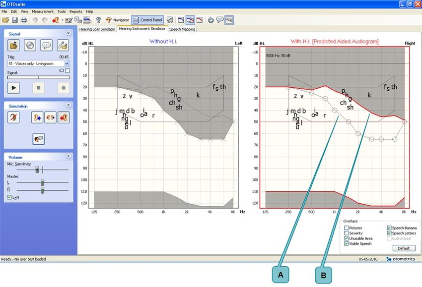
Copyright notice
    © 2012, 2021 Natus Medical Denmark ApS. All rights reserved. ® Natus, the Natus Icon, Aurical, Madsen, HI-PRO 2, Otoscan, ICS
    and HORTMANN are registered trademarks of Natus Medical Denmark ApS in the U.S.A. and/or other countries.
    Version release date
    2021/01/26
    Technical support
    Please contact your supplier.

2                                                                                                               AURICAL FreeFit
User Guide

             Table of Contents

              1   Device description                                    4

              2   Intended use                                          4

              3   Unpacking                                             5

              4   Installation                                          6

              5   Powering the device                                   6

              6   Switching AURICAL FreeFit on or off                   7

              7   Connecting AURICAL FreeFit to PMM                     8

              8   AURICAL FreeFit probes                                8

              9   Toolbar icons in PMM and Counseling and Simulations   12

              10 Simulating hearing loss                                13

              11 Simulating hearing instruments                         15

              12 Speech Mapping                                         18

              13 Performing probe microphone measurements               18

              14 Demonstrating hearing instrument features              22

              15 Service, cleaning and maintenance                      23

              16 Other references                                       24

              17 Technical specifications                               24

              18 Warning notes                                          28

              19 Notes on EMC (Electromagnetic Compatibility)           29

              20 Definition of symbols                                  34

              21 Manufacturer                                           36

AURICAL FreeFit                                                                      3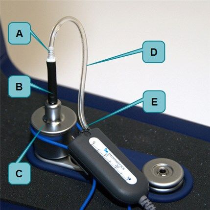
User Guide

1            Device description
1.1          Brief description
             AURICAL FreeFit is a four-channel frequency analyzer used for measuring the sound pressure level close to the client's
             eardrum as well as outside the ear by the pinna for both ears simultaneously.
             AURICAL FreeFit should only be charged using the type 1053 charger unit or the type 1081 AURICAL speaker unit from
             Natus.

             Type 1053 charger unit                  AURICAL speaker unit with charger

               Note • This manual describes the assembly and use of the type 1053 charger unit. If you use the AURICAL speaker unit
               to charge your FreeFit, see the manual for AURICAL Aud.

               Note • For information about the Counseling and Simulations software, see the manual for AURICAL Visible Speech
               and the Counseling and Simulations Module.

             You use the Otosuite PMM module and the Counseling and Simulations module to operate AURICAL FreeFit. AURICAL
             FreeFit cannot be used without Otosuite software.

1.2          Physical operating principle
             Aurical® FreeFit uses loudspeakers to generate reference sound pressures. By placing built-in microphones close to a cli-
             ent’s eardrums as well as outside the ears, the four channels are used for measuring the sound pressure level at the
             eardrum as well as outside the ear for both ears simultaneously. In this way, FreeFit and the PMM module enable you to
             perform true binaural measurements that provide you with valuable information when you adjust hearing instrument set-
             tings in the suppliers’ fitting software.

2            Intended use
             Users: audiologists, hearing instrument dispensers, ENTs, speech therapists and other health care professionals.

4                                                                                                                         AURICAL FreeFit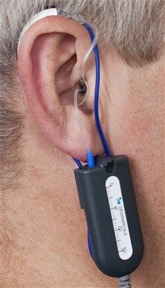
User Guide

             Use: to visualize the amplified signal recorded in the ear with reference information such as target curves to provide an
             objective basis for adjusting the hearing instrument settings.

2.1          Typographical conventions
             The use of Warning, Caution and Note
             To draw your attention to information regarding safe and appropriate use of the device or software, the manual uses pre-
             cautionary statements as follows:

                  Warning • Indicates that there is a risk of death or serious injury to the user or patient.

                  Caution • Indicates that there is a risk of injury to the user or patient or risk of damage to data or the device.

                  Note • Indicates that you should take special notice.

             To obtain a free printed copy of the user documentation, contact Natus Medical Denmark ApS (www.natus.com).

3            Unpacking
             1. Unpack the device carefully.
                When you unpack the device and accessories, it is a good idea to keep the packing material in which they were
                delivered. If you need to send the device in for service, the original packing material will protect against damage dur-
                ing transport, etc.
             2. Visually inspect the equipment for possible damage.
                If damage has occurred, do not put the device into operation. Contact your local distributor for assistance.
             3. Check with the packing list to make sure that you have received all necessary parts and accessories. If your package is
                incomplete, contact your local distributor.

AURICAL FreeFit                                                                                                                                5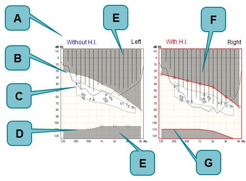
User Guide

4            Installation

                                                                                          Mounting the NOAHLink charger on the
             Installation for desk top use         Wall mount installation
                                                                                          AURICAL FreeFit charger base plate

5            Powering the device
               Caution • Use only the following battery types:
               Rechargeable, Ni-MH, AA (R6) 1.2V, 1 pc.(Use only rechargeable batteries supplied by Natus). Can also be used with
               Alkaline AA (R6) 1.5V, 1 pc.

             A. Press to open

6                                                                                                                      AURICAL FreeFit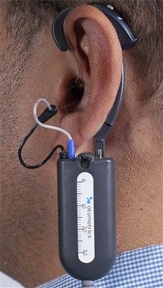
User Guide

5.1          Recharging the battery using the charger stand
                           Warning • If you are using an alkaline battery, do not attempt to charge your AURICAL FreeFit. Your
                           alkaline battery may be damaged and leak, and this may in turn cause damage to AURICAL FreeFit. Place
                           FreeFit in the charger unit only if AURICAL FreeFit contains a rechargeable battery.
                           Batteries should be removed if equipment is not likely to be used for some time.

                           Caution • Use only the power supplies specified in Technical specifications, Power supply. See Technical spe-
                           cifications ► 24.

                  Note • Replace rechargeable battery once a year. New batteries must be purchased from Natus.

6            Switching AURICAL FreeFit on or off
                  Warning • Unless you are charging AURICAL FreeFit with the Aurical® Aud speaker unit, which has a medically isol-
                  ated power supply unit, do not attempt to use AURICAL FreeFit with clients while it is placed in the charger unit.

             Switching on AURICAL FreeFit
             Press and hold the power button on top of the device until the status indicator light turns on. The status indicator will
             light for about 3 seconds, and then go into periodic flashing.

             Switching off AURICAL FreeFit
             Press and hold the power button on top of the device until the status indicator light turns off.

AURICAL FreeFit                                                                                                                            7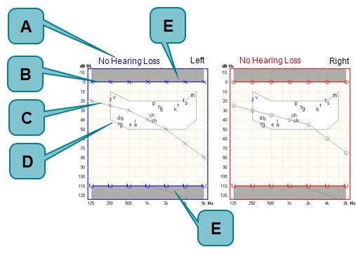
User Guide

             A. Power button

7            Connecting AURICAL FreeFit to PMM
             When you use PMM for the first time, run the configuration wizard to set up the connection between AURICAL FreeFit
             and PMM.
             After you have configured PMM for the first time, if FreeFit is turned on when you open the Control Panel in PMM, then
             FreeFit will connect to PMM automatically. Otherwise, you can connect FreeFit as follows:
             1. Switch on FreeFit.
             2. In PMM, on the toolbar, click Control Panel (Control Panel).
             3. In the control panel, click Connect (Connect).

8            AURICAL FreeFit probes
             Probe with original accessories

             A.   Probe tube port                            E. Probe tube
             B.   Marker ring                                F. Transducer tube port (RECD probe only)
             C.   Ear cord                                   G. Probe housing
             D.   Probe tube support

8                                                                                                                    AURICAL FreeFit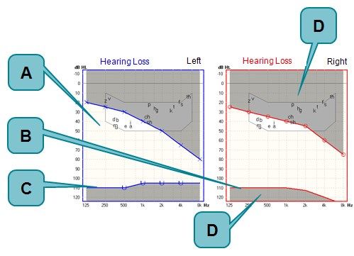
User Guide

             Probe with probe enhancement accessories

             A.    Probe tube port                               E. Probe tube with millimeter markings
             B.    Marker ring                                   F. Transducer tube port (RECD probe only)
             C.    Probe tube support                            G. Probe housing
             D.    Ear hook

             The ear cord or ear hook is used to hang the probe below the client's ear. The probe tube is inserted into the ear canal for
             probe microphone measurements. The probe tube has a black marker ring for marking how far into the ear canal the tube
             should be inserted. The probe tube support is used to stabilize the position of the probe tube. Before you make RECD
             measurements, you fit a transducer tube on the transducer tube port.

8.1          Fitting probe tubes on the probes
             A bag of silicone probe tubes is supplied together with AURICAL FreeFit.

             To fit a probe tube on the probe
             Fit a probe tube to the probe tube port (thin metal tube) at the top of the probe housing. Gently push and twist the probe
             tube down as far as possible over the port.

8.2          Calibrating the probe tubes

                  Note • To prevent cross-infection, use new probe tubes for each client.

             1. Fit a new probe tube on the probe.
             2. Insert the free end of the probe tube in the test location on the probe.

AURICAL FreeFit                                                                                                                             9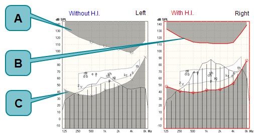
User Guide

                 A. Probe tube
                 B. Test location for probe tube calibration

             3. Make sure that AURICAL FreeFit is connected to PMM.
             4. Press the power button briefly on AURICAL FreeFit.
                 The Probe Tube Calibration (Probe Tube Calibration) dialog box appears and the calibration starts automatically.

                           Alternatively, launch the wizard with the toolbar icon. In RECD, pressing the power button starts an ear
                           measurement.

             5. If the tube calibration fails, check whether the tubes are blocked (pinched or clogged) and try to eliminate sources of
                ambient noise.

8.3          Fitting the probes on the client and inserting the probe tubes
             It is important that the probe tube for every measurement is inserted correctly and consistently in the ear of the client.
             For adults and children 16 years and older, it is recommended to use the ProbeTube Assistant to assist you with pos-
             itioning the probe tubes. Alternatively, you can place the tubes based on recommended distances.
             1. Place the black marker ring at the recommended distance from the tip of the probe tube.
             2. If the reference point of the black marker ring is the intertragus notch, you can add 8 mm for the concha depth.

               Note • To avoid touching the ear drum, you must take into account that the probe tube should not be inserted closer
               to the ear drum than 4 mm.

10                                                                                                                        AURICAL FreeFit
User Guide
Note • The length of ear canal may vary from country to country and even depending on the physical size of
the patient, so make sure that you take this into account when you use the recommended distances.
Note • In the case of children, otoscopy is especially recommended to prevent contact with the eardrum.
Recommended distances
The recommended distances are based on the complete average lengths of ear canals, where the reference point is
at the opening of the ear canal.
Men 25-29 mm
Women 22-26 mm
Children from 6 months 18-22 mm
Distances are based on:
• ISO 12124:2001
• Wayne Staab, The Human Ear Canal -V, July 7, 2014.
• Voss SE(1), Herrmann BS. How does the sound pressure generated by circumaural, supra-aural, and insert
earphones differ for adult and infant ears? Ear Hear. 2005 Dec; 26(6):636-50.
3. Place the ear cords or ear hooks with the probes over the ears of the client. Adjust the length of the ear cords or ear
hooks, if required.
With original probe accessories With probe enhancement accessories
4. Be careful!
Carefully insert the probe tube into the ear canal until the black marker ring reaches the intertragal notch.
AURICAL FreeFit 11User Guide
9 Toolbar icons in PMM and Counseling and
Simulations
The icons available in the toolbar depend on the test function that you have selected.
Toolbar icons in PMM and Counseling and Simulations
Select device.
Toggle between Response, Gain, REIG and Predicted Aided Audiogram (PAA) views.
(PMM)
Select view:
HL (HL): Hearing Level or SPL (SPL): Sound Pressure Level
Select audiogram view: Left, both or right
Open Fitting Details (Fitting Details) dialog. (PMM)
Note • You must select the Use OpenREM calibration (Use OpenREM calibration)
option if you are fitting an open ear instrument.
Open Listen at the Eardrum (Listen at the Eardrum)/Listen in the Coupler (Listen in the
Coupler) window to record the signal at the eardrum or in the coupler, or monitor the
signal through your headphones.
(PMM)
Show/hide Legend (Legend) and Overlays (Overlays) box.
Switch to Feature-2-Benefit (Feature-2-Benefit) view.
(PMM - FreeStyle only)
Launch probe tube calibration wizard.
Toggle between standard calibration and OpenREM calibration.
(PMM)
12 AURICAL FreeFitUser Guide
Toolbar icons in PMM and Counseling and Simulations
Select previously measured RECD values.
(RECD only)
Toggle between coupler fitting mode and Real Ear fitting mode.
(PMM)
Show/Hide OnTarget (OnTarget) view, which displays the difference between the tar-
get curve and the measured curve.
(Aided Response only)
Open the Live Video Otoscopy (Live Video Otoscopy) window on top of the current tab
to view otoscopy video from Otocam.
(PMM)
Open the ProbeTube Assistant for guided assistance in placing the probe tube in the
patient's ear canal.
Switch to On Top (On Top) mode.
Click to reload the original audiogram.
(Simulators only)
Display the Predicted Aided Audiogram.
(Hearing Instrument Simulator only)
Select text file to read aloud.
(Counseling and Simulations only)
10 Simulating hearing loss
The buttons that are available in the Control Panel depend on:
• The Speaker Channel (Speaker Channel) setting in the Configuration Wizard (Left (Left) or Right (Right) for one speaker
or Left + Right (Left + Right) for two speakers)
• The Sound Output (Sound Output) setting in Options (Options) (Headphone (Headphone) or Speaker (Speaker)).
Hearing Loss Simulator - with headphones or two speakers
Play the selected signal. While the signal plays, you can switch between presenting the signal in the following modes:
• without hearing loss simulation, or
AURICAL FreeFit 13User Guide
• with hearing loss simulation for both ears.
Note • When you use headphones or two speakers, you can use the volume slider to lower the volume of one speaker
or headphone, in order to demonstrate one ear at a time.
Hearing Loss Simulator - with one speaker
Play the selected signal. While the signal plays, you can switch between presenting the signal in the following modes:
• without hearing loss simulation, or
• with hearing loss simulation for selected ears. (If you select Both (Both), the hearing
or losses from both ears are simulated together in the single speaker.)
10.1 Without simulation
A. Status indicator D. Speech Banana and Speech Letters (default overlays)
B. Normal HTLs E. Unusable Area (default overlay)
C. Client's HTLs (inactive)
14 AURICAL FreeFitUser Guide
10.2 With simulation
A. Area of opportunity C. Measured UCL (symbols)
B. Predicted UCL (no symbols) D. Unusable Area (default overlay)
11 Simulating hearing instruments
The buttons that are available in the Control Panel depend on:
• The Speaker Channel (Speaker Channel) setting in the Configuration Wizard (Left (Left) or Right (Right) for one speaker
or Left + Right (Left + Right) for two speakers)
• The Sound Output (Sound Output) setting in Options (Options) (Headphone (Headphone) or Speaker (Speaker)).
Hearing Instrument Simulator - with one speaker
Play the selected signal. While the signal plays, you can switch between presenting the signal in the following modes:
• without hearing instrument simulation, or
• with hearing instrument simulation for selected ear.
or
Hearing Instrument Simulator - with two speakers
Play the selected signal. While the signal plays, you can switch between presenting the signal in the following modes:
AURICAL FreeFit 15User Guide
• without hearing instrument simulation, or
• with hearing instrument simulation for both ears.
Hearing Instrument Simulator - with headphones
Play the selected signal. While the signal plays, you can switch between presenting the signal in the following modes:
• without hearing instrument simulation, or
• with hearing instrument simulation for selected ear or both ears.
or
11.1 With versus without hearing instrument simulation - HL
A. Status indicator E. Unusable Area (default overlay)
B. Client’s HTLs (inactive) F. Counseling and Simulations spectrum (default over-
C. Customized Speech Banana and Speech Letters (default lay)
overlays) G. Predicted UCL (no symbols)
D. Measured UCL (symbols)
Use the customized speech banana to explain the concept of reduced dynamic range and the purpose of compression in
hearing instruments.
16 AURICAL FreeFitUser Guide
11.2 With versus without Hearing Instrument Simulation - SPL
A. Measured UCL (symbols) C. Client’s HTLs
B. Predicted UCL (no symbols)
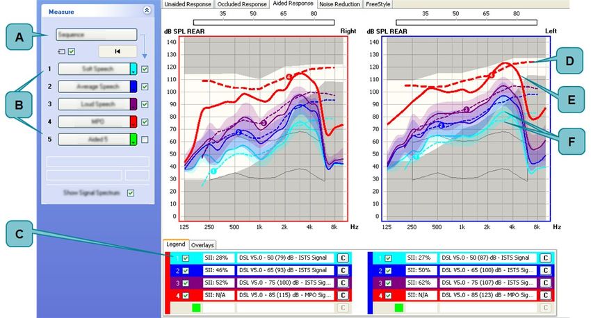
11.3 The Predicted Aided Audiogram view
A. Client's HTL
B. Predicted Aided Audiogram
AURICAL FreeFit 17User Guide
In the Predicted Aided Audiogram view, the traditional speech banana is displayed instead of the customized speech
banana. When you simulate use of a hearing instrument, the audiogram is displayed with a lowered threshold, to demon-
strate that the client would have access to a greater part of the sound signal, and thereby improved access to the speech
banana.
The displayed values are the client’s thresholds minus the target insertion gain.
12 Speech Mapping
The Speech Mapping (Speech Mapping) screen in Counseling and Simulations (Counseling and Simulations) allows you to
perform probe microphone measurements to demonstrate that speech sounds that are amplified by the hearing instru-
ment are audible, and are presented within the client's remaining hearing range.
If you are using AURICAL FreeFit, you can use the FreeStyle (FreeStyle) screen in PMM for this purpose.
13 Performing probe microphone measurements
When you start a new session in PMM, you must ensure the fitting parameters are set correctly in the Fitting Details (Fit-
ting Details) dialog box.
Note • If previous measurement data for the current patient exist in the system, the settings from the latest meas-
urements will automatically be applied to the new session for that patient.
To adjust the fitting parameters
1. Press F10 to open the Fitting Details (Fitting Details) dialog box.
2. Select the appropriate target rule.
3. Fill in the remaining fields in the dialog box.
Making Probe Microphone Measurements
The following sections describe the main procedures involved in PMM:
Measuring RECD ► 18
Measuring Unaided Response ► 20
Measuring Occluded Response ► 21
Measuring Aided Response ► 21
13.1 Measuring RECD
If you want to use measured RECD values for coupler based fitting, you can measure RECD in PMM as follows:
Measure coupler response:
Skip this procedure if you have a stored coupler measurement.
1. Open the RECD (RECD) tab in PMM.
18 AURICAL FreeFitUser Guide
2. Indicate the type of coupler adapter you are using, and whether you are using an earmold or foam insert tip.
3. Click Coupler Response... (Coupler Response...) in the RECD Control Panel.
4. Attach the right RECD ear probe to the coupler in Aurical® HIT.
A. RECD coupling
B. BTE adapter tube
C. BTE (HA2) adapter
D. Transducer tubing
E. Transducer tube port
5. Click the Measure Right (Measure Right) button.
6. Connect the left probe to the coupler in Aurical® HIT.
7. Click the Measure Left (Measure Left) button.
8. Click OK (OK).
9. Remove the probe from Aurical® HIT and remove the RECD coupling from the tubing of the BTE coupler.
Then measure real ear response:
1. Attach the probes to the FreeFit.
2. Perform probe tube calibration.
3. Connect the RECD coupling to the earmold tubing (or foam insert tip).
A. Transducer tubing
B. RECD coupling
C. earmold or foam insert tip
D. Transducer tube port
E. Probe tube
4. Place the probe tubes in the client’s ears together with the earmolds or foam insert tips (see Fitting the probes on
the client and inserting the probe tubes ► 10).
AURICAL FreeFit 19User Guide
5. Select ear to measure.
6. In the control panel, click Ear Response (Ear Response) (or briefly press the power button on the FreeFit).
The measured ear response and the RECD are displayed in their respective graphs.
13.2 Measuring Unaided Response
In the Unaided (Unaided) screen, measure without hearing instruments to determine the natural amplification of the ear
canal.
1. Insert probe tube.
2. Select ear to measure.
3. Select graph.
4. Click the Unaided (Unaided) button on the Control Panel.
Note • In an unaided measurement, we usually expect a peak on the measurement curve around the 3kHz frequency of
about 10-20 dB SPL.
20 AURICAL FreeFitUser Guide
A. UCL C. Peak around 3 kHz
B. Audiogram D. Measurement curve
13.3 Measuring Occluded Response
In the Occluded Response (Occluded Response) screen, measure with muted hearing instruments in ears to measure the
occlusion or openness of the fitting.
1. Place the hearing instrument on the ear of the patient, with the probe tube inserted in the ear canal. Ensure the hear-
ing instrument is muted or turned off.
2. Click the Occluded (Occluded) button on the Control Panel.
When you compare the REUR to the REOR, you can see the impact of the occlusion of the ear canal.
13.4 Measuring Aided Response
In the Aided (Aided) screen, measure the gain that the hearing instruments are providing in relation to a specified pre-
scriptive fitting target.
1. Place the hearing instrument on the ear of the patient, with the probe tube inserted in the ear canal.
Note • For Coupler based fitting, select the Coupler based fitting icon on the toolbar and attach the hearing
instrument to the coupler in Aurical® HIT (see the manual for Aurical® HIT).
2. Switch the hearing aid on without moving it.
All the hearing instrument features should be left on with the general use program selected.
3. Configure the control panel to play up to 5 signals. For example: 3 input levels for a speech or speech-like stimulus:
Soft (50/55 dB SPL), Average (65 dB SPL) and Loud (80 dB SPL) plus an MPO stimulus.
4. Present the various input levels and MPO signal separately or in one sequence.
AURICAL FreeFit 21User Guide
5. Compare the measured aided response curve to the prescriptive target values (dashed curve) and the measured MPO
curve to the UCL. Consider adjusting the MPO (Maximum Power Output) if indicated by any report of loudness dis-
comfort.
6. Adjust the hearing instrument with the fitting software to achieve the desired gain, and repeat the measurements to
evaluate the effects of the changes.
A. Sequence button D. Target curve for MPO.
B. Measurement buttons for different stimuli E. Measurement curve for MPO.
C. Curve legend for button 1. F. Measurement curve and target curve for button 1.
You can also select OnTarget (OnTarget) view, which shows a live display of the difference between the target
curve and the measured curve. This makes it easier to adjust the HI programming.
14 Demonstrating hearing instrument features
Use the Noise Reduction (Noise Reduction) screen to evaluate and demonstrate the hearing instrument’s noise reduction
feature. Each Noise Reduction test is an automatic sequence that contains two curves (with a delay between the two
curves):
• Curve 1 – a snapshot taken immediately before Noise Reduction takes effect.
• Curve 2 – a snapshot taken automatically after the selected Adaptation Interval, when the Noise Reduction has taken
effect.
To demonstrate the Noise Reduction feature:
1. Program the hearing instrument for the desired Noise Reduction setting.
22 AURICAL FreeFitUser Guide
2. Configure the measurement buttons to demonstrate the conditions you prefer. For each button, select the time dif-
ference between the two measurements (Curve 1 and Curve 2).
3. Click a measurement button in the control panel.
The snapshot curves are displayed in the graph and the overall Noise Reduction is displayed in the curve legend.
The Feature-2-Benefit (Feature-2-Benefit) view gives you the opportunity to see and show the gain difference
in an easy to understand graph.
The FreeStyle (FreeStyle) test screen is similar to the other PMM test screens but with numerous possibilities to cus-
tomize protocols.
15 Service, cleaning and maintenance
Warning • Under no circumstances disassemble AURICAL FreeFit or the AURICAL FreeFit charger. Contact your sup-
plier. Parts inside AURICAL FreeFit and the AURICAL FreeFit charger must only be checked or serviced by authorized
personnel.
15.1 Service
For the sake of safety and in order not to void the warranty, service and repair of electro-medical equipment should be car-
ried out only by the equipment manufacturer or by service personnel at authorized workshops. In case of any defects,
make a detailed description of the defect(s) and contact your supplier. Do not use a defective device.
15.2 Cleaning
Use a soft, slightly damp cloth with a small amount of mild detergent or approved non-caustic medical grade disinfectant
wipes to clean the unit and charger according to local infection control regulations.
Keep the unit away from liquids. Do not allow moisture inside the unit. Moisture inside the unit can damage the instru-
ment and it may result in a risk of electrical shock to the user or patient.
Caution • Never immerse the AURICAL FreeFit probes into water or other cleaning solutions.
Caution • No part of AURICAL FreeFit or its accessories is suitable for autoclaving or thermal disinfection/sterilization
methods.
Probe tubes, tube guides and ear cords or ear hooks
These parts are in constant contact with your clients.
AURICAL FreeFit 23User Guide
• Probe tubes:
The only part which is inserted into the ear canal during PMM testing is the Probe tube. These tubes are disposable,
and should only be used once per client.
• Tube guides and ear cords or ear hooks:
Use a soft, slightly damp cloth with a small amount of detergent to clean the ear cords or ear hooks and the tube
guides.
Disposal
There are no special requirements regarding the disposal of the silicone test tubes, i.e. they can be discarded according to
local regulations.
15.3 Maintenance
Annual replacement of the rechargeable battery
Replace the rechargeable battery with a new rechargeable battery (part number 031814) every year. For more inform-
ation, refer to the FreeFit Reference Manual.
Annual calibration
FreeFit and the FreeFit probes must be calibrated once a year by your authorized service department.
16 Other references
For more information, see the online Help in Otosuite, which contains detailed reference information about AURICAL
FreeFit and the Otosuite modules.
For Otosuite installation instructions, see the Otosuite Installation Guide, on the Otosuite installation medium.
17 Technical specifications
AURICAL FreeFit
Type identification
AURICAL FreeFit is type 1053 from Natus Medical Denmark ApS
Interface
Interface Wireless Bluetooth data transfer to PC, version 2.0, + EDR, class 2 (10
meters/33ft).
24 AURICAL FreeFitUser Guide
BT antenna
BT antenna: Chip multilayer antenna for 2.4 GHz
Antenna gain: 2 dBi
Antenna impedance: 50 Ohm
The device supports Bluetooth SIG standards and uses features and functions from connected peripherals such as displaying
the working status on the console from a Bluetooth connection.
The device with Bluetooth technology, which operates in the same spectrum range in the 2.400 GHz-2.4835GHz (ISM
band) as Classic Bluetooth technology, uses Bluetooth technology's 79 1-MHz wide channels. Within the channel, data is
transmitted using Gaussian frequency shift modulation (GFSK), similar to Classic Bluetooth's Basic Rate scheme. The bit rate
is 1 Mbit/s.
Power supply
Battery types: Rechargeable, Ni-MH, AA (R6) 1.2V, 1 pc.(Use only rechargeable batteries sup-
plied by Natus). Can also be used with Alkaline AA (R6) 1.5V, 1 pc.
Battery supply voltage: Nom. 1.30 V,
Max. 1.65 V,
Min. start-up: 1.10 V (Measured with instrument load)
Min. when running: 1.00 V
Low battery indicator level: When approximately 30 minutes of battery operating time remain.
Estimated battery life: 5 hours of continuous use. (This is based on a typical use scenario. The actual
use can influence the battery life time).
Accessories
• Test software. See the AURICAL FreeFit Service Manual.
Charger unit
Note • This manual describes the assembly and use of the type 1053 charger unit. If you use the AURICAL speaker unit
to charge your FreeFit, refer to the technical specifications in the manual for Aurical® Aud.
Type identification
Charger unit is type 1053 Charger from Natus Medical Denmark ApS
Power supply
Nominal input voltage: 9 V DC
Min. input voltage: 6.5 V DC
Max. input voltage: 12 V DC
Max. power consumption while charging: 300 mA (at 9 V input voltage)
AURICAL FreeFit 25User Guide
Max. power consumption when not char- 60 mA (at 9 V input voltage)
ging:
External power adaptor
Power supply: BRIDGEPOWER CORP, Input voltage range: 100-240 V AC, 50-60 Hz
MENB1010A0903B01 Output voltage range: 9 V DC, 1.10 A
Power supply: DONGGUAN SHILONG Input voltage range: 100-240 V AC, 50-60 Hz
FUHUA ELECTRONIC CO., LTD., UE08WCP- Output voltage range: 9 V DC, 0.56 A
090056SPA
Power supply: DONGGUAN SHILONG Input voltage range: 100-240 V AC, 50-60 Hz
FUHUA ELECTRONIC CO., LTD., Output voltage range: 9 V DC, 0.6 A
UES06WNCP-090060SPA
Use only the power adaptor supplied with the instrument.
Operating environment
Mode of operation: Continuous.
Temperature: +15°C to +35°C (59°F to +95°F)
Relative humidity: 30 to 90%, non-condensing
Warm-up time: < 1 min.
Air pressure: 600 hPa to 1060 hPa
Operation at temperatures below -20°C or above +60°C may cause permanent damage.
Storage and handling
Temperature: -20°C to +60°C (-4°F to +140°F)
Rel. humidity: < 90%, non-condensing
Air pressure: 500 hPa to 1060 hPa
Dimensions
AURICAL FreeFit (HxWxD): 23 mm x 350 mm x 230 mm (0.91 x 13.7 x 9.1 inches)
Charger unit (HxWxD): 280 mm x 180 mm x 230 mm (11.4 x 7.1 x 9.1 inches) (with table plate moun-
ted)
340 mm x 180 mm x 230 mm (13.8 x 7.1 x 9.1 inches) (with wall plate moun-
ted)
Weight
AURICAL FreeFit: 0.180 kg/0.40 lb
Charger unit: 0.700 kg/1.54 lb
Essential performance
Aurical® FreeFit has no essential performance and accordingly, the applicable requirements are as stated in the following:
26 AURICAL FreeFitUser Guide
• Basic safety as defined by IEC 60601-1
All information required by IEC 60601-1-2:2007, #5.2.2.1-#5.2.2.10 is available in the Aurical® FreeFit User Guide.
Standards
Real Ear Measurement: EN 61669:2001, ISO 12124:2001
Safety: IEC 60601-1:2005+A1:2012, Internally Powered Type BF IPX0
EN 60601-1:2006+A1:2013, Type BF
ANSI/AAMI ES60601-1:2005 + A1:2012
CAN/CSA-C22.2 NO. 60601-1:14
EMC: IEC 60601-1-2:2014 and EN 60601-1-2:2015
IEC 60601-1-2:2007 and EN 60601-1-2:2007
Radio Equipment: ETSI EN 300 328 V2.1.1 (2016)
17.1 Accessories
Standard accessories and optional accessories vary from country to country - please consult your local distributor.
• REM Probes (2 pieces) - cable length approximately 20 cm (7.9 in)
• RECD Probes - short (2 pieces) - cable length approximately 20 cm (7.9 in)
• RECD Probe - long (1 piece) - cable length approximately 150 cm (5 feet)
• REM Probe Tubes (50 pieces)
• Silicone Ear Cords (50 pieces)
• Ear Hooks
• SoundHub 100
• Headphone, semi-closed (customer) - cable length approximately 250 cm (8 feet)
• Headset, open (dispenser) - cable length approximately 200 cm (6.5 feet)
• Table-top microphone (recording) - cable length approximately 300 cm (100 feet)
• NOAHlink straps
• Velcro clips
• Y-splitter adaptor cable
• REM tube support
• Otosuite DVD
• OTOair Bluetooth Dongle
• RECD fitting kit (tubing and coupling)
• RECD Eartip starter kit
• Rechargeable, Ni-MH, AA (R6) 1.2V, 1 pc. PN#031814
• AURICAL FreeFit Reference Manual
• AURICAL FreeFit User Guide
AURICAL FreeFit 27User Guide
18 Warning notes
This manual contains information and warnings, which must be followed to ensure the safe performance of the devices and
software covered by this manual. Local government rules and regulations, if applicable, should also be followed at all times.
AURICAL FreeFit should only be provided with prescribed battery types, see Powering the device ► 6.
Place the battery as indicated in the battery compartment.
If you are using an alkaline battery, do not attempt to charge your AURICAL FreeFit. Your alkaline battery may
be damaged and leak, and this may in turn cause damage to AURICAL FreeFit. Place FreeFit in the charger unit
only if AURICAL FreeFit contains a rechargeable battery.
Batteries should be removed if equipment is not likely to be used for some time.
AURICAL FreeFit should only be charged using the type 1053 charger unit or the type 1081 AURICAL speaker
unit from Natus.
Unless you are charging AURICAL FreeFit with the Aurical® Aud speaker unit, which has a medically isolated
power supply unit, do not attempt to use AURICAL FreeFit with clients while it is placed in the charger unit.
1. There are no user-serviceable parts inside the cabinet of the device or charger. For the sake of safety and in order not
to void the warranty, service and repair of electro-medical equipment should be carried out only by the equipment
manufacturer or by service personnel at authorized workshops. In case of any defects, make a detailed description of
the defect(s) and contact your supplier. Do not use a defective device.
2. Keep the unit away from liquids. Do not allow moisture inside the unit. Moisture inside the unit can damage the
instrument and it may result in a risk of electrical shock to the user or patient.
3. Do not use the instrument in the presence of flammable agents (gases) or in an oxygen-rich environment.
4. Unwanted noise may occur if the device is exposed to a strong radio field. Such noise may interfere with the per-
formance of the device. Many types of electrical devices, e.g. mobile telephones, may generate radio fields. We
recommend that the use of such devices in the vicinity of AURICAL FreeFit be restricted.
5. Changes or modifications not expressly approved by the manufacturer could void the user's authority to operate the
equipment.
6. This equipment has been tested and found to comply with the limits for a Class B digital device, pursuant to part 15 of
the FCC Rules. These limits are designed to provide reasonable protection against harmful interference in a residential
installation. This equipment generates, uses and can radiate radio frequency energy and, if not installed and used in
accordance with the instructions, may cause harmful interference to radio communications. However, there is no guar-
antee that interference will not occur in a particular installation. If this equipment does cause harmful interference to
radio or television reception, which can be determined by turning the equipment off and on, the user is encouraged
to try to correct the interference by one or more of the following measures:
– Reorient or relocate the receiving antenna.
– Increase the separation between the equipment and receiver.
– Connect the equipment into an outlet on a circuit different from that to which the receiver is connected.
– Consult the dealer or an experienced radio/TV technician for help.
7. For use in Canada: To prevent radio interference to the licensed service, this device is intended to be operated
indoors and away from windows to provide maximum shielding. Equipment (or its transmit antenna) that is installed
outdoors is subject to licensing.
28 AURICAL FreeFitUser Guide
8. No parts may be eaten, burnt, or in any way used for purposes other than the applications defined in the Intended Use
section of this manual.
9. The device and charger unit can be disposed of as normal electronic waste, according to local regulations. Please
investigate local regulations concerning the disposal of rechargeable and alkaline batteries.
10. For safety reasons and due to effects on EMC, accessories connected to the equipment's outlet fittings must be
identical to the type supplied with the system.
11. It is recommended that an annual calibration be performed on accessories containing transducers. Furthermore, it is
recommended that calibration be performed if the equipment has suffered any potential damage (e.g. headphones
dropped on the floor).
12. To comply with EN 60601-1-1 computer and printer must be placed out of reach of the client, i.e. not closer than
approx. 1.5 meters/5 ft.
13. We recommend that the device should not be stacked with other equipment or placed in a poorly ventilated space as
this may affect the performance of the device. If it is stacked or placed adjacent to other equipment, make sure that
the operation of the device is not affected.
14. In the United States of America, Federal law restricts this device to sale by or on the order of a licensed physician.
15. It is recommended to install the unit in an environment that minimizes the amount of static electricity. For example,
anti-static carpeting is recommended.
16. The charger unit should be kept away from the client area.
19 Notes on EMC (Electromagnetic Compatibility)
• AURICAL FreeFit is part of a medical electrical system and is thus subject to special safety precautions. For this reason,
the installation and operating instructions provided in this document should be followed closely.
• Portable and mobile high-frequency communication devices, such as mobile phones, may interfere with the func-
tioning of AURICAL FreeFit.
IEC 60601-1-2:2014 and EN 60601-1-2:2015
Guidance and manufacturer's declaration - electromagnetic emissions for all equipment and systems
AURICAL FreeFit is intended for use in the electromagnetic environment specified below. The user of AURICAL FreeFit should ensure that it is used in such an
environment.
Emissions test Compliance Electromagnetic environment - guidance
RF emissions Group 1 AURICAL FreeFit uses RF energy only for its internal function. Therefore, its RF emissions are very
CISPR11 low and are not likely to cause any interference in nearby electronic equipment.
RF emissions Class B AURICAL FreeFit is suitable for use in all environments, including domestic environments and
CISPR11 those directly connected to the public low-voltage power supply network that supplies buildings
used for domestic purposes.
AURICAL FreeFit 29User Guide
Harmonic emissions IEC Not applicable
61000-3-2
Voltage fluctuations/flicker Not applicable
emissions IEC 61000-3-3
Guidance and manufacturer's declaration - electromagnetic immunity for all equipment and systems
AURICAL FreeFit is intended for use in the electromagnetic environment specified below. The user of AURICAL FreeFit should ensure that it is used in such an
environment.
Immunity test IEC 60601 Compliance level Electromagnetic environment - guidance
test level
Electrostatic discharge (ESD) +/- 8 kV contact +/- 8 kV contact Floors should be wood, concrete or ceramic tile. If floors
IEC 61000-4-2 +/- 2 kV, +/- 4 kV, +/- 2 kV, +/- 4 kV, are covered with synthetic material, the relative humid-
+/- 8 kV, +/- 15 kV air +/- 8 kV, +/- 15 kV air ity should be at least 30 %.
Electrical fast transient/burst +/- 2 kV for power supply lines +/- 2 kV for power supply lines Mains power quality should be that of a typical com-
IEC 61000-4-4 +/- 1 kV for input/output lines +/- 1 kV for input/output lines mercial or hospital environment.
Surge +/- 1 kV line(s) to line(s) +/- 1 kV line(s) to line(s) Mains power quality should be that of a typical com-
IEC 61000-4-5 +/- 2 kV line(s) to earth Not applicable mercial or hospital environment.
+/- 2 kV DC input line(s) to earth Not applicable
+/- 1 kV DC input line(s) to line(s) +/- 1 kV DC input line(s) to line(s)
+/- 2 kV I/O line(s) to earth Not applicable
Voltage dips, short inter- 0 % U ; 0.5 cycle 0 % U ; 0.5 cycle Mains power quality should be that of a typical com-
ruptions and voltage vari-
T T
At 0°, 45°, 90°, 135°, 180°, 225°, 270° At 0°, 45°, 90°, 135°, 180°, 225°, 270° mercial or hospital environment. If the user of the
ations on power supply input and 315° and 315° AURICAL FreeFit requires continued operation during
lines 0 % U ; 1 cycle 0 % U ; 1 cycle power mains interruptions, it is recommended that the
IEC 61000-4-11 and
T and
T AURICAL FreeFit be powered from an uninterruptible
70 % U ; 25/30 cycles 70 % U ; 25/30 cycles power supply or a battery.
T
Single phase: at 0°
T
Single phase: at 0°
Voltage interruptions on 0 % U ; 250/300 cycles 0 % U ; 250/300 cycles
power supply input lines
T T
IEC 61000-4-11
Power frequency 30 A/m No relevant ports that could be Power frequency magnetic fields should be at levels char-
(50/60 Hz) magnetic field affected acteristic of a typical location in a typical commercial or
IEC 61000-4-8 hospital environment.
U
T is the AC mains voltage prior to application of the test level.
Guidance and manufacturer's declaration - electromagnetic immunity - for equipment and systems within Professional Healthcare use environment
AURICAL FreeFit is intended for use in the electromagnetic environment specified below. The user of AURICAL FreeFit should ensure that it is used in such an
environment.
30 AURICAL FreeFitUser Guide
Immunity test IEC 60601 Compliance level Electromagnetic environment - guidance
test level
Conducted RF 3 V rms 3 V rms
IEC 61000-4-6 150 kHz to 80 MHz 150 kHz to 80 MHz
6 V rms 6 V rms
ISM Bands and Amateur ISM Bands and Amateur
Radiated RF 10 V/m 10 V/m
IEC 61000-4-3 80 MHz to 2.7 GHz 80 MHz to 2.7 GHz
3 V/m 3 V/m
80 MHz to 2.7 GHz 80 MHz to 2.7 GHz
Proximity fields from RF wire- 27 V/m 27 V/m Separation distance between any electronic parts of
less communications 385 MHz 385 MHz AURICAL FreeFit and any RF wireless communication
IEC 61000-4-3 equipment must be more than 30 cm (11.8 inches).
28 V/m 28 V/m
450 MHz 450 MHz
9 V/m 9 V/m
710 MHz, 745 MHz, 780 MHz 710 MHz, 745 MHz, 780 MHz
28 V/m 28 V/m
810 MHz, 870 MHz, 930 MHz 810 MHz, 870 MHz, 930 MHz
28 V/m 28 V/m
1720 MHz, 1845 MHz, 1970 MHz 1720 MHz, 1845 MHz, 1970 MHz
28 V/m 28 V/m
2450 MHz 2450 MHz
9 V/m 9 V/m
5240 MHz, 5500 MHz, 5785 MHz 5240 MHz, 5500 MHz, 5785 MHz
Note 1: At 80 MHz and 800 MHz the separation distance for the higher frequency range applies.
Note 2: These guidelines may not apply in all situations. Electromagnetic propagation is affected by absorption and reflection from structures, objects and
people.
IEC 60601-1-2:2007 and EN 60601-1-2:2007
Guidance and manufacturer's declaration - electromagnetic emissions for all equipment and systems
AURICAL FreeFit is intended for use in the electromagnetic environment specified below. The user of AURICAL FreeFit should ensure that it is used in such an
environment.
Emissions test Compliance Electromagnetic environment - guidance
RF emissions Group 1 AURICAL FreeFit uses RF energy only for its internal function. Therefore, its RF emissions are
CISPR11 very low and are not likely to cause any interference in nearby electronic equipment.
AURICAL FreeFit 31User Guide
RF emissions Class B AURICAL FreeFit is suitable for use in all environments, including domestic environments and
CISPR11 those directly connected to the public low-voltage power supply network that supplies
buildings used for domestic purposes.
Harmonic emissions IEC 61000-3-2 Not applicable
Voltage fluctuations/flicker emissions IEC Not applicable
61000-3-3
Guidance and manufacturer's declaration - electromagnetic immunity for all equipment and systems
AURICAL FreeFit is intended for use in the electromagnetic environment specified below. The user of AURICAL FreeFit should ensure that it is used in such an
environment.
Immunity test IEC 60601 Compliance level Electromagnetic environment - guidance
test level
Electrostatic dis- +/- 6 kV contact +/- 6 kV contact Floors should be wood, concrete or ceramic tile. If floors are covered with syn-
charge (ESD) +/- 8 kV air +/- 8 kV air thetic material, the relative humidity should be at least 30 %.
IEC 61000-4-2
Power frequency 3 A/m 3 A/m Power frequency magnetic fields should be at levels characteristic of a typical loc-
(50/60 Hz) magnetic ation in a typical commercial or hospital environment.
field
IEC 61000-4-8
32 AURICAL FreeFitUser Guide
Guidance and manufacturer's declaration - electromagnetic immunity - for equipment and systems that are NOT life-supporting
AURICAL FreeFit is intended for use in the electromagnetic environment specified below. The user of AURICAL FreeFit should ensure that it is used in such an
environment.
Immunity test IEC 60601 Compliance level Electromagnetic environment - guidance
test level
Radiated RF 3 V/m 3 V/m Portable and mobile RF communications equip-
IEC 61000-4-3 80 MHz to 2.5 GHz ment should be used no closer to any part of
AURICAL FreeFit, including cables, than the recom-
mended separation distance calculated from the
equation applicable to the frequency of the trans-
mitter.
Recommended separation distance:
d = 1.2 for 80 MHz to 800 MHz
d = 2.3 for 80 MHz to 2.5 GHz,
where P is the maximum output power rating of
the transmitter in watts (W) according to the trans-
mitter manufacturer and d is the recommended
separation distance in metres (m).
Field strengths from fixed RF transmitters, as
determined by an electromagnetic site survey, a
should be less than the compliance level in each
frequency range. b
Interference may occur in the vicinity of equip-
ment marked with this symbol:
Note 1: At 80 MHz and 800 MHz the separation distance for the higher frequency range applies.
Note 2: These guidelines may not apply in all situations. Electromagnetic propagation is affected by absorption and reflection from structures, objects and
people.
a. Field strengths from fixed transmitters, such as base stations for radio (cellular/cordless) telephones and land mobile radios, amateur radio, AM and FM radio
broadcast and TV broadcast cannot be predicted theoretically with accuracy. To assess the electromagnetic environment due to fixed RF transmitters, an
electromagnetic site survey should be considered. If the measured field strength in the location in which AURICAL FreeFit is used exceeds the applicable RF
compliance level above, the AURICAL FreeFit should be observed to verify normal operation. If abnormal performance is observed, additional measures
might be necessary, such as reorienting or relocating AURICAL FreeFit.
b. Over the frequency range 150 kHz to 80 MHz, field strengths should be less than 3 V/m.
Recommended separation distances between portable and mobile RF communications equipment and AURICAL FreeFit
The AURICAL FreeFit is intended for use in an electromagnetic environment in which radiated RF disturbances are controlled. The customer or the user of the
AURICAL FreeFit can help prevent electromagnetic interference by maintaining a minimum distance between portable and mobile RF communications equip-
ment (transmitters) and the AURICAL FreeFit as recommended below, according to the maximum output power of the communications equipment.
AURICAL FreeFit 33User Guide
Rated maximum output power of transmitter Separation distance according to frequency of transmitter
W m
80 MHz to 800 MHz 800 MHz to 2.5 GHz
d = 1.2 d = 2.3
0.01 0.12 0.23
0.1 0.38 0.73
1 1.2 2.3
10 3.8 7.3
100 12 23
For transmitters rated at a maximum output power not listed above, the recommended separation distance d in meters (m) can be estimated using the equa-
tion applicable to the frequency of the transmitter, where P is the maximum output power rating of the transmitter in watts (W) according to the transmitter
manufacturer.
Note 1: At 80 MHz and 800 MHz the separation distance for the higher frequency range applies.
Note 2: These guidelines may not apply in all situations. Electromagnetic propagation is affected by absorption and reflection from structures, objects and
people.
20 Definition of symbols
Manufacturer
Indicates the medical device manufacturer, as defined in EU Directives 90/385/EEC, 93/42/EEC
ISO 15223-1 and 98/79/EC.
Symbol 5.1.1
Caution
Indicates the need for the user to consult the instructions for use for important cautionary inform-
ISO 15223-1 ation such as warnings and precautions that cannot, for a variety of reasons, be presented on the
Symbol 5.4.4 and medical device itself.
IEC 60601-1
Table D.1 #10
Follow instructions for use
IEC 60601-1
Table D.2 #10
34 AURICAL FreeFitUser Guide
Consult instructions for use
Indicates the need for the user to consult the instructions for use.
ISO 15223-1
Symbol 5.4.3 and
IEC 60601-1
Table D.1 #11
Type BF applied part
Complies with Type BF requirements of IEC 60601-1.
IEC 60601-1
Table D.1 #20
CE marking of conformity
Certification mark that indicates conformity with applicable regulations and directives for the
European Economic Area.
93/42/EEC
The installation must be carried out in accordance with Medical Electrical Systems clause 16 in
IEC 60601-1 (3rd), AAMI ES60601-1 and CSA C22.2 NO. 60601-1-08-CAN/CSA. The supplementary
provisions on the reliability of electro-medical systems.
It is a general rule for all electrical equipment used in the proximity of the client that:
• The connected equipment must comply with IEC 60601-1 (3rd).
This device complies with part 15 of the FCC rules. Operation is subject to the following two con-
ditions:
• This device must not cause harmful interference.
• This device must accept any interference received, including interference that may cause
undesired operation.
The term ”IC” before the certification/registration number signifies that the Industry Canada tech-
nical specifications were met.
In France, it is only permitted to use the device indoors.
Identifies the correct position of the battery inside the battery compartment.
Interference may occur in the vicinity of the device. Local regulations and precautions for other
equipment in the environment should always be followed to avoid interference.
The separation distance from this device to other devices complying with standard immunity
requirements in IEC 60601-1-2 is minimum 0.35 m/1ft.
Direct current
Indicates that the device is suitable for direct current only.
AURICAL FreeFit 35User Guide
Do not reuse.
Indicates a medical device that is intended for one use, or for use on a single patient during a
single procedure.
Used in error message dialogs if software program fails. See the detailed information in the dialog
box.
Electronic equipment covered by the Directive 2012/19/EU of the European Parliament and of
the Council of 4 July 2012 on waste electrical and electronic equipment (WEEE).
All electrical and electronic products, batteries, and accumulators must be taken to separate col-
EN 50419
lection at the end of their working life. This requirement applies in the European Union. Do not
dispose of these products as unsorted municipal waste.
You can return your device and accessories to Natus Medical Denmark ApS, or to any Natus
Medical Denmark ApS supplier. You can also contact your local authorities for advice on disposal.
See the full Natus Medical Denmark ApS WEEE statement below.
WEEE Statement
Natus is committed to meeting the requirements of the European Union WEEE (Waste Electrical and Electronic Equip-
ment) Regulations 2014. These regulations state that electrical and electronic waste must be separately collected for the
proper treatment and recovery to ensure that WEEE is reused or recycled safely. In line with that commitment Natus may
pass along the obligation for take back and recycling to the end user, unless other arrangements have been made. Please
contact us for details on the collection and recovery systems available to you in your region at www.natus.com.
Electrical and electronic equipment (EEE) contains materials, components and substances that may be hazardous and
present a risk to human health and the environment when WEEE is not handled correctly. Therefore, end users also have a
role to play in ensuring that WEEE is reused and recycled safely. Users of electrical and electronic equipment must not dis-
card WEEE together with other wastes. Users must use the municipal collection schemes or the producer/importers take-
back obligation or licensed waste carriers to reduce adverse environmental impacts in connection with disposal of waste
electrical and electronic equipment and to increase opportunities for reuse, recycling and recovery of waste electrical and
electronic equipment.
Equipment marked with the crossed-out wheeled bin is electrical and electronic equipment. The crossed-out wheeled bin
symbol indicates that waste electrical and electronic equipment should not be discarded together with unseparated waste
but must be collected separately.
21 Manufacturer
Natus Medical Denmark ApS
Hoerskaetten 9, 2630 Taastrup
Denmark
+45 45 75 55 55
www.natus.com
36 AURICAL FreeFitUser Guide
21.1 Responsibility of the manufacturer
The manufacturer is to be considered responsible for effects on safety, reliability, and performance of the equipment only
if:
• All assembly operations, extensions, re-adjustments, modifications or repairs are carried out by the equipment man-
ufacturer or personnel authorized by the manufacturer.
• The electrical installation to which the equipment is connected complies with EN/IEC requirements.
• The equipment is used in accordance with the instructions for use.
The manufacturer reserves the right to disclaim all responsibility for the operating safety, reliability and performance of
equipment serviced or repaired by other parties.
AURICAL FreeFit 37You can also read