Automatic Dense Annotation for Monocular 3D Scene Understanding
←
→
Page content transcription
If your browser does not render page correctly, please read the page content below

Received February 8, 2020, accepted March 3, 2020. Date of publication xxxx 00, 0000, date of current version xxxx 00, 0000.
Digital Object Identifier 10.1109/ACCESS.2020.2984745

Automatic Dense Annotation for Monocular 3D
Scene Understanding
MD ALIMOOR REZA 1 , KAI CHEN                                1,   AKSHAY NAIK              1,   DAVID J. CRANDALL                  1,

AND SOON-HEUNG JUNG 2
1 Luddy   School of Informatics, Computing, and Engineering, Indiana University, Bloomington, IN 47408, USA
2 Electronics and Telecommunications Research Institute, Daejeon 34129, South Korea
Corresponding author: Md Alimoor Reza (mdreza@iu.edu)
This work was supported in part by the Electronics and Telecommunications Research Institute (ETRI) grant funded by the Korean
Government (Development of Fundamental Technology for Hyper-Realistic Media Space), under Grant 19ZR1100, and in part by the
National Science Foundation under Grant CAREER IIS-1253549.

  ABSTRACT Deep neural networks have revolutionized many areas of computer vision, but they require
  notoriously large amounts of labeled training data. For tasks such as semantic segmentation and monocular
  3d scene layout estimation, collecting high-quality training data is extremely laborious because dense, pixel-
  level ground truth is required and must be annotated by hand. In this paper, we present two techniques
  for significantly reducing the manual annotation effort involved in collecting large training datasets. The
  tools are designed to allow rapid annotation of entire videos collected by RGBD cameras, thus generating
  thousands of ground-truth frames to use for training. First, we propose a fully-automatic approach to produce
  dense pixel-level semantic segmentation maps. The technique uses noisy evidence from pre-trained object
  detectors and scene layout estimators and incorporates spatial and temporal context in a conditional random
  field formulation. Second, we propose a semi-automatic technique for dense annotation of 3d geometry, and
  in particular, the 3d poses of planes in indoor scenes. This technique requires a human to quickly annotate
  just a handful of keyframes per video, and then uses the camera poses and geometric reasoning to propagate
  these labels through an entire video sequence. Experimental results indicate that the technique could be used
  as an alternative or complementary source of training data, allowing large-scale data to be collected with
  minimal human effort.

  INDEX TERMS Scene understanding, 3D reconstruction, semi-supervised learning, computer vision.

I. INTRODUCTION                                                                                    However, humans are often able to infer 3d scene structure
Understanding the semantic, three-dimensional structure of                                      from 2d photos, including the identity of objects and approx-
the visual world is a fundamental problem in computer vision,                                   imate 3d layout, even when there is significant occlusion
with innumerable applications ranging from automatic photo                                      between scene elements. To do this, we use a variety of
retrieval to autonomous vehicles. A particularly difficult                                      cues including perspective, relative object size and position,
problem is to understand scene content from a single image.                                     shadows, etc., combined with intuition from a lifetime of
When a photograph is taken, the projective transformation                                       experience about the world [1]. Encoding this reasoning into
‘‘converts’’ a 3d scene into a 2d image, throwing away most                                     an automatic algorithm has been a long-standing goal of
explicit cues about depths of points in the scene. Reversing                                    computer vision, but has proven difficult: human-level perfor-
this process — understanding three-dimensional scenes from                                      mance requires not just low-level image cues, but also higher-
two-dimensional images — is very difficult, and in fact is                                      level semantic cues: identifying objects, reasoning about their
mathematically ill-posed, because of the inherent ambiguity                                     typical relationships, applying the laws of nature, etc.
in the task.                                                                                       Understanding indoor scenes poses particular problems.
                                                                                                Indoor spaces have relatively textureless surfaces such as
                                                                                                walls, making it difficult to identify distinctive keypoints for
    The associate editor coordinating the review of this manuscript and                         matching or analysis. Moreover, in indoor photos the distance
approving it for publication was Thomas Canhao Xu                .                              between the camera and scene is usually small, exacerbat-

                      This work is licensed under a Creative Commons Attribution 4.0 License. For more information, see https://creativecommons.org/licenses/by/4.0/
VOLUME 8, 2020                                                                                                                                                         1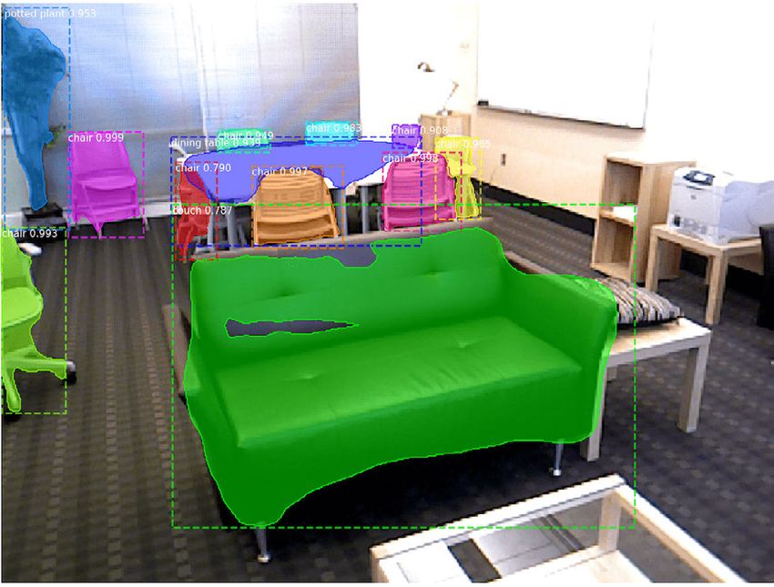
M. A. Reza et al.: Automatic Dense Annotation for Monocular 3D Scene Understanding

ing problems with perspective distortion and lens artifacts.          with just a small amount of human labor. We assume that
On the other hand, reconstruction of indoor scenes can benefit        we have RGBD data (from a depth camera) to assist this
from strong prior information about the world: rooms usually          annotation.
consist of prominent planar surfaces (walls, ceiling, floor)             This work builds on previous approaches that have asked
that intersect at 90 degree angles, and rooms of specific             humans to label a few keyframes, and then automatically
types usually contain common objects in certain canonical             propagate these annotations across the entire video [10]–[12].
configurations (e.g., living room with couches, kitchen with          We first consider how to annotate semantic segmentation
table and chairs, etc.).                                              maps. Instead of requiring human annotation, we rely on
   Recently, progress on problems related to scene under-             signals from an object detector [13] applied to various object
standing, including object recognition and 3d scene layout            categories (e.g., bed, tv, etc.). To account for the remain-
estimation, has accelerated because of the dramatic suc-              ing regions that are not explained by the object detectors,
cess of deep learning on many computer vision problems.               we automatically estimate the 3D layout of the scene, which
Although the exact mechanism for this success is not fully            helps to identify background regions. We then introduce a
understood, one common hypothesis is that modern deep                 novel energy minimization-based formulation for solving for
learning models – especially convolutional neural networks –          dense pixel-level annotations over an entire video. This work
are particularly adept at capturing regularities of the visual        is based on preliminary results that were presented at IROS
structure of the world. In the context of monocular 3d scene          2019 [14].
reconstruction, for example, this means that deep neural                 We then turn to annotate training data for 3d room layout.
networks trained on large-scale scene datasets can provide            Unfortunately, this is not just a simple matter of scanning
powerful models of the ‘‘prior distribution’’ of the real visual      scenes in 3d: there is a fundamental problem with collecting
world, allowing the networks to produce a plausible 3d model          data from range scanners and fitting 3d models to those
despite the inherent ambiguity of the 2d-to-3d problem.               point clouds, because the data is sparse and errors are sim-
   However, the major disadvantage of these techniques is             ply unavoidable. We propose a semi-automatic method of
that they require large-scale training data, typically on the         estimating the 3d wire-frame or skeleton of an indoor scene.
order of tens of thousands to millions of images. Worse               The skeletal structure can be represented as a collection of 3d
than the quantity of imagery, though, is the density of labels        lines that intersect with each other at junctions such as floor-
needed for many tasks. For example, two critical tasks for            wall and ceiling-wall intersections. From these structures,
understanding scenes are semantic segmentation [2]–[4] —              high-quality training data for our monocular depth estimation
identifying meaningful pixel regions in an image and assign-          model can be produced.
ing object or material labels to each of them — and estimating           To summarize, we make the following contributions:
the 3d structure of the scene [5]–[9]. Unfortunately, train-             • First, we propose a novel method to densely annotate
ing modern machine learning-based algorithms for either of                 pixels of an indoor scene for semantic segmentation. Our
these problems requires the extremely labor-intensive process              method combines masks from pre-trained object detec-
of densely annotating an image pixel-by-pixel, typically by                tors with the estimated indoor scene layout to explain
hand. This severely restricts the amount of training data                  all the pixels in an image including the background
that can be collected for these methods, which means that                  (Figure 1). We formulate the pixel-level annotation in a
researchers tend to use training datasets that are convenient              Conditional Random Field (CRF) energy minimization
instead of the ones that are best suited for a particular prob-            framework, to use the regularities between successive
lem. This, in turn, limits the performance of these algorithms             video frames to produce a consistent annotation over the
in real-world applications.                                                entire video.
   In this paper, we explore how to collect large-scale training         • Second, we propose a novel method that allows human
data with minimal human interaction for these two tasks:                   annotators to quickly draw the rough 3d structure of an
semantic segmentation and 3d room layout from single                       indoor scene in a few keyframes, and then propagates
images. Our approach is to develop a novel algorithm and tool              those layouts automatically across video frames. The
that allows people to provide quick, high-level annotations                annotations required in each keyframe are very sparse
about the content and geometry of an image. We increase                    and easy to provide (e.g., 2d annotations of line segment
annotation speed by several orders of magnitude by doing                   endpoints).
this annotation on video clips instead of single images. Video           • Finally, we show that our automatic annotations can be
is an attractive source of data because a single video may                 used to train data-hungry Deep Neural Networks.
have thousands of frames, showing an environment from
many different perspectives as the camera moves around                II. RELATED WORK
the environment. Moreover, because the frames of a video              Our semi-automatic annotation tools are tested on two crucial
are correlated, hand-labeled ground truth is less onerous to          tasks for 3d scene understanding: semantic segmentation, and
collect, since annotations can be semi-automatically propa-           3d scene layout estimation. We briefly review work on these
gated from one frame to the next. The end result is thou-             two applications, as well as general work related to semi-
sands of individual images with high-quality annotations, but         automatic video annotation.

2                                                                                                                                 VOLUME 8, 2020
M. A. Reza et al.: Automatic Dense Annotation for Monocular 3D Scene Understanding

                                                                               frames: in fact, deep learning has arguably breathed new life
                                                                               into a problem that was too difficult for the traditional tech-
                                                                               niques that had been deployed before. Wang et al. [7] propose
                                                                               an end-to-end deep learning architecture that estimates a 3D
                                                                               shape in the form of a triangular mesh from a single color
                                                                               image. Lee et al. [22] combine deep learning with inspira-
                                                                               tion from traditional techniques based on Fourier analysis
                                                                               for single-image depth estimation. Zhao et al. [23] propose
FIGURE 1. We automatically annotate indoor scenes for training semantic        a simple feed-forward deep neural network that yields low
segmentation models. Images (left) are automatically annotated (right)         reconstruction errors when reconstructing 3d from a single
based on off-the-shelf object detectors and a 3D room layout estimator.
                                                                               image of a 2D object. Laina et al. [24] introduces another end-
                                                                               to-end trainable deeper neural network with a reverse Huber
A. SEMANTIC SEGMENTATION                                                       loss function for depth estimation from a single RGB image.
Before the advent of Deep Convolutional Neural Networks                           While those techniques focus on reconstructing single
(DCNNs), semantic segmentation was usually performed                           objects, other work has applied deep learning to reconstruct
bottom-up using hand-engineered features [15]. Deep neural                     the layout of an entire indoor scene. Mallya et al. [8] pro-
networks have since surpassed these earlier approaches with                    pose a box-shaped room layout prediction method by using
high accuracy. One successful application of an end-to-end                     informative edge maps from an RGB image. Im2CAD [9]
trainable convolutional network for semantic segmentation                      was inspired by Roberts’ classic Block World [25] paper,
is the Fully Convolution Network (FCN) of Long et al. [2].                     and attempts to infer a complete 3D interpretation of a
This idea was further refined by SegNet [3]. To mitigate                       scene photo including the layout of the room by exploiting
the cost of pixel-level annotation, Dong et al. [16] recently                  deep neural network features and leveraging a rich database
proposed a few-shot semantic segmentation approach that                        of 3D CAD models to replicate various indoor objects
learns a DCNN model from very few annotated images.                            such as table, chair, bed, etc. LayoutNet [26] proposes a
   Semantic segmentation is closely related to object detec-                   generic framework for room layout estimation from a single
tion, which identifies objects in an image along with their                    RGB image. The proposed architecture follows an encoder-
locations (typically in the form of bounding boxes). SSD [17],                 decoder architecture that receives 6-channel input (3-channel
YOLO [18], and Mask R-CNN [13] are popular choices.                            RGB and 3-channel Manhattan constraint line-segments).
For example, Mask R-CNN [13] detects objects by first cre-                     Lee et al. [27] propose RoomNet, an end-to-end network that
ating regions of interest, performing classification on each                   maps monocular RGB room images to keypoint-based room
region and then using per-class non-maximal suppression                        structure images. Their model jointly predicts both scene type
to avoid duplicate bounding boxes. For our work, we use                        and room layout in the form of keypoint (i.e., corners of a
Mask R-CNN, since it also provides segmentation masks for                      room) positions.
detected objects.                                                                 Huang et al. [28] propose FrameNet, a model to learn
   Of course, a key challenge with these models is how to col-                 a canonical frame from a RGB image, where a canonical
lect the densely-annotated training data to permit supervised                  frame is represented by three orthogonal directions, one
training. Castrejon et al. [19] learned a Recurrent Neural                     along the normal direction and two in the tangent plane.
Network (RNN) model that could predict the polygonal ver-                      Dasgupta et al. [29] propose a novel method called DeLay for
tices encompassing an object inside a cropped RGB image.                       room layout estimation from a single monocular RGB image
This method includes an interactive tool to correct predic-                    that uses a CNN model to generate an initial belief map,
tion errors. EasyLabel [20] is a semi-automatic method for                     which is then used by an optimization algorithm to predict
annotating objects on the RGB-D table-top setting. Label-                      the final room layout. This model makes a strong Manhattan
Fusion [21] is another semi-automatic method for generating                    World assumption — i.e., that the room is cuboid in shape.
large quantities of semantic labels from RGB-D videos. This                    Liu et al. [30] introduce PlaneNet, a Dilated Residual Net-
method receives user annotations on the 3D reconstruction                      work (DRN) to predict plane parameters and corresponding
of the environment, which are then used to propagate the                       segmentation masks. They are able to produce piece-wise
labels across the frames in the RGB-D video. Unlike these                      planar and semantically meaningful structures from a single
methods, we propose a fully automatic method for labeling                      RGB image. A major caveat of this work is the assumption
all pixels — covering a range of categories from small objects                 that the number of planes in a room is fixed. This hard
to large furniture and background — for all the images in an                   constraint has been eliminated in the follow-up work called
RGB-D video, as well as annotating the 3d scene structure of                   PlaneRCNN [5], where the detection module can detect any
the indoor scenes.                                                             arbitrary number of planes present in a scene.
                                                                                  Of course, deep learning is notoriously data-hungry, and so
B. MONOCULAR DEPTH ESTIMATION                                                  progress in deep learning for 3d reconstruction has required
As with semantic segmentation, deep learning has revolu-                       collecting large labeled datasets for training and testing.
tionized the study of reconstructing 3d from single RGB                        Yi et al. [31] introduce a large-scale 3D shape understanding

VOLUME 8, 2020                                                                                                                              3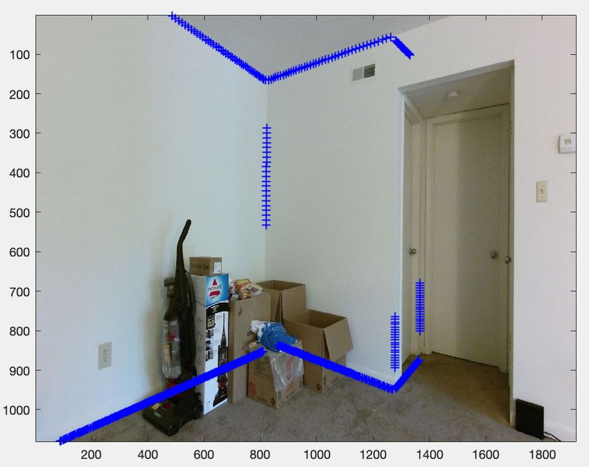
M. A. Reza et al.: Automatic Dense Annotation for Monocular 3D Scene Understanding

benchmark using data and annotations from the ShapeNet 3D             for these two different categories. Object detectors allow us
object database [32]. Sun et al. [6] introduced a large-scale         to incorporate annotation information for the various specific
benchmark (Pix3D) of diverse image-shape pairs with pixel-            object categories, such as ‘‘bed,’’ ‘‘chair,’’ ‘‘tv,’’ etc. But a
level 2D-3D alignment. Prior datasets typically contained             large fraction of the pixels in an indoor scene consist of
only synthetic data or lacked precise alignment between 2D            background categories such as ‘‘wall,’’ ‘‘ceiling,’’ ‘‘floor,’’
images and 3D shapes, but Pix3D has better dataset statis-            ‘‘window,’’ etc. In order to annotate the pixels for these
tics and better performance in quantitative evaluations. Raw          background categories not explained by an object detector,
images were collected from web search engines and shapes              we resort to 3D layout estimation of the scene. Information
were collected from 3D repositories, and then the labeled             from these two complementary sources is fused together by
keypoints on the 2D images and 3D shapes were used for the            solving an energy minimization problem in a Conditional
alignment.                                                            Random Field (CRF) framework. Figure 2 shows the pipeline
   Other datasets have been collected for whole scenes instead        of our methodology. We now describe these components in
of just objects, but these datasets typically have many images        detail.
but lower-quality annotations. For example, the Active Vision
Dataset (AVD) [33] contains diverse indoor environment                A. OBJECT DETECTION
types across multiple geographic locations in the United              Object detection [17], [18] identifies the objects present in an
States. Each video was captured by a camera mounted on a              image along with their locations in the form of rectangular
robot which was directed to roam through the rooms inside             bounding boxes. To find a coarse segmentation mask of each
various apartments. SUN3D [34] consists of thousands of               detected object, we use the object segmentation method of
RGBD frames captured across various indoor locations in               Mask-RCNN [13]. Figure 3 (top row) shows detection results
university campuses and dormitories. Only a fraction of these         on images from two different scenes in our experiments.
frames have been manually annotated. Our approach can be              Notice that while the object identifications and boundaries
applied to any of these RGBD video datasets, allowing us to           are generally accurate, a large fraction of pixels that are in the
quickly annotate existing video data with rich annotations on         background are not labeled. We find the annotation informa-
scene structure.                                                      tion for these image pixels by estimating the structural layout
                                                                      of the scene.
C. OTHER RELATED WORK
Our techniques are related to general work on semi-automatic          B. 3D SCENE LAYOUT ESTIMATION
video labeling. Most of these techniques start with man-              The approximate structure of a typical indoor scene consists
ual annotations of a few keyframes, and then propagate                of a set of 3D planes intersecting with each other. Individual
those annotations across the remaining frames using cues              components of these planar structures can typically be labeled
such as spatial proximity, optical flow, or 3D reconstruction         as ‘‘wall,’’ ‘‘floor,’’ ‘‘ceiling,’’ etc. Finding and identifying
[10]–[12], [34], [35]. Many of these techniques are similar in        these planes is an open research question, of course — it
nature to those used in object tracking.                              is part of the motivation behind this paper, since we need
   Another strategy for dealing with limited training data is         to collect more high-quality training data to produce bet-
to generate synthetic data [36], [37], but a caveat is that deep      ter scene layout estimators. To break this chicken-and-egg
neural networks trained with synthetic data may not perform           problem, we used a traditional technique not based on deep
well when applied on real-world images. Tsutsui et al. [38]           learning, and thus less sensitive to shifts in application or
found that synthetic training images actually hurt the perfor-        context. After experimenting with various of these, we settled
mance of fine-grained object recognition, but creating learned        on the approach of Taylor et al. [39], which estimates the
mixtures of synthetic and real images was effective. How-             structure of the scene by first finding 3D planes utilizing
ever, the improvement was quite small and it still requires           the depth channel from an RGB-D image, and then assigns
large-scale labeled training data. While these techniques will        labels to each plane based on its estimated normal. The
continue to improve, a more effective approach in the mean-           plane aligned to the gravity direction is labeled as ‘‘floor,’’
time may be to generate annotated data directly from natural          the plane orthogonal to the ‘‘floor’’ is labeled ‘‘wall,’’ and
images. In this paper, we address this problem and propose            the remaining portion of the layout is labeled as ‘‘ceiling.’’
an automatic method for generating annotations from frames            Figure 3 shows the estimated scene layout components for
of video sequences.                                                   two sample images.

III. AUTOMATIC TRAINING DATA ANNOTATION FOR                           C. SUPERPIXELS
SEMANTIC SEGMENTATION                                                 An image superpixel is a set of contiguous pixels that share
We address the problem of automatically annotating all the            homogeneity in appearance, texture, etc. [40]–[42]. A super-
pixels in a frame from an indoor video without any human              pixel generation algorithm partitions the image into a reduced
annotation. Most pixels in an indoor scene belong to one of           number of segments, thereby speeding up the work of sub-
two broad categories: object or background. To automatically          sequent processing which can process partitions instead of
annotate all the pixels in an image, we need to find labels           individual pixels. Reza et al. [10] generated high-quality

4                                                                                                                                 VOLUME 8, 2020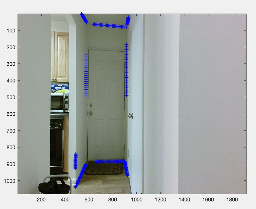
M. A. Reza et al.: Automatic Dense Annotation for Monocular 3D Scene Understanding

     FIGURE 2. For each video frame, we identify candidate object masks using pre-trained object detectors (top branch). The pixels not explained
     by the detector are estimated from 3d scene layout (bottom branch). This evidence is combined in an energy minimization framework to
     estimate our final annotation.

                                                                               we would like to minimize,
                                                                                                                     X
                                                                                 E(Xk |Ik , Ik−1 , Ik−2 , Ik−3 ) =         θi (xi ; Ik )
                                                                                                                     i∈V
                                                                                                                         X
                                                                                                                     +         φi (xi ; Ik−1 , Ik−2 , Ik−3 )
                                                                                                                         i∈V
                                                                                                                           X
                                                                                                                     +             ψij (xi , xj ; Ik ),   (1)
                                                                                                                         (i,j)∈ζ

                                                                               where θi (.) and φi (.) are the unary energy functions and
                                                                               ψij (.) is the pairwise function. The CRF graph G = (V , ζ )
                                                                               is defined over the pixels in the image Ik and 4-connected
                                                                               neighbors. We use the 3 frames immediately preceding Ik ,
                                                                               namely Ik−1 , Ik−2 , and Ik−3 , and exploit their unaries com-
                                                                               puted earlier by transferring them into the current frame using
                                                                               optical flow. This ensures temporal smoothness in finding the
FIGURE 3. Sample detection and 3D room layout results from two
different scenes: Studyroom (Left) and MIT-32 (Right) from SUN3D [34].
                                                                               annotation for the current frame.
Detector outputs (top) from Mask RCNN [13] provide an initial coarse
segmentation around detected objects, while 3D layout estimation
                                                                               UNARY TERMS
(below) explains background categories including ‘‘wall,’’ ‘‘floor,’’
and ‘‘ceiling.’’                                                               From the detector output, we obtain a set of detected object
                                                                               masks along with their labels. For the background category,
                                                                               the predicted layout mask intersects with almost the entire
superpixels, but relied on an expensive image-contour gen-                     image. We assign a fixed score to all the pixels that overlap
eration process that can take several minutes per image.                       with our various background categories (such as ‘‘wall,’’
In contrast, we follow a simpler and more efficient alternative,               ‘‘floor,’’ ‘‘ceiling,’’ etc.). Figure 3 shows detection masks in
SLIC (Simple Linear Iterative Clustering) [41], which can                      different colors along with their label on the top-left corner of
generate superpixels in less than a second. Figure 4(b) shows                  each bounding box. We find the intersection of a mask with
superpixel boundaries overlaid on an image from our experi-                    a superpixel, and within each superpixel distribute the same
ments. We use our superpixels as atomic units to incorporate                   score to all the pixels.
annotation information from our two complementary sources                         More specifically, we compute our first unary term,
of evidence, object detection and 3d scene layout estimation.
                                                                                                    θi (xi ; Ik ) = −f (xi ; Ik ),                        (2)
D. PIXELWISE ANNOTATION                                                        where f (.) is a score for the pixel i computed by the superpixel
We assume that we are given a video sequence consisting                        that engulfs it. For each superpixel, we count the fraction of
of frames {I1 , I2 , . . . , IN }. For a given unannotated frame Ik ,          pixels that overlap with the detection mask of object aj . As an

VOLUME 8, 2020                                                                                                                                                 5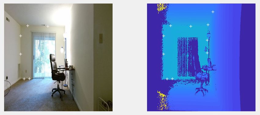
M. A. Reza et al.: Automatic Dense Annotation for Monocular 3D Scene Understanding

      FIGURE 4. Visualization of our energy minimization formulation. (a) For each frame, we (b) identify candidate object segmentation masks
      from pre-trained object detectors [13]. (d) The remaining pixels are estimated from the layout of the scene [39]. These are combined via
      energy minimization to estimate our final annotation (h). In addition to a unary term (e) from the current frame, we incorporate a second
      unary (g) that encodes evidence from previous frames, using optical flow as shown in (f).

                                                                                    Equation (1) is minimized using Graph Cuts [43] inference.
                                                                                 A summary of the steps for finding the automatic annotation
                                                                                 for an image is shown in Figure 4.

                                                                                 IV. VIDEO GEOMETRIC LABEL GENERATION
FIGURE 5. Detection masks on three successive frames in a video
sequence. Notice that the detector fires inconsistently on the same              We now turn to generate data for our second problem of
instance of ‘‘chair’’ object category. Our formulation can handle this noise     key importance in scene understanding: automatic 3d lay-
with a unary term φ(.) that encourages temporal consistency across
frames.
                                                                                 out estimation from single 2d images. Our approach is to
                                                                                 develop a novel algorithm and tool that allows humans to
example, if a detection mask from the ‘‘chair’’ category com-                    provide quick, high-level annotations about the geometry
pletely overlaps with a superpixel, then f (.) assigns a score                   of an image, and then use those annotations to fit a planar
of 1.0 for ‘‘chair’’ category. Figure 4(b) shows an example of                   room layout structure to noisy, 3d depth maps. When the
our unary energy term for different annotation categories.                       RGBD data is a video from a moving camera of a sta-
   Our second unary term is,                                                     tionary scene, our approach is able to propagate the anno-
                                                                                 tations across time to unlabeled frames, thus reducing the
     φi (xi ; Ik−1 , Ik−2 , Ik−3 ) = −g(xi ; Ik−1 , Ik−2 , Ik−3 ),      (3)      amount of human labor involved by several orders of mag-
where g(.) is another scoring function based on the unary                        nitude. We also assume that the camera poses of the indi-
energy terms for the three frames immediately preceding                          vidual video frames are available as a prior, which could be
frame Ik , in particular taking the average of the unary energy                  estimated from the standard Structure from Motion (SfM)
terms from the frames Ik−1 , Ik−2 , and Ik−3 by transferring                     pipeline [44].
them into frame Ik using optical flow. Figure 5 shows a                             In particular, we propose a semi-automatic method of esti-
situation that demands this temporal consistency for finding                     mating the 3D layout of indoor scenes, in the form of a
the correct annotation.                                                          wire-frame or skeleton. The skeletal structure can be rep-
                                                                                 resented as a collection of 3d lines that intersect with each
PAIRWISE TERM
                                                                                 other at junctions such as floor-wall and ceiling-wall intersec-
                                                                                 tions. Our goal is to semi-automatically estimate this wire-
To encourage smoothness, we adopt a simple Potts model for
                                                                                 frame structure of the indoor scene for all the frames in
our pairwise energy function, which penalizes adjacent pixels
                                                                                 an RGB-D video, in order to produce high-quality training
having different annotations,
                                    (                                            data for our monocular depth estimation model. We esti-
                                     0, xi = xj                                  mate the 3D wire-frame structure of a scene in two stages:
              ψij (xi , xj ; Ik ) =                       (4)                    (i) Corner point annotation in a few keyframes and ii) Lay-
                                     b, xi 6 = xj ,
                                                                                 out estimation for the entire video utilizing the annotated
where b was empirically set to 0.5 for all our experiments.                      keyframes.

6                                                                                                                                            VOLUME 8, 2020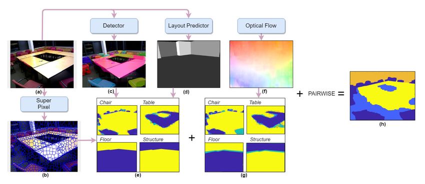
M. A. Reza et al.: Automatic Dense Annotation for Monocular 3D Scene Understanding
TABLE 1. Quantitative evaluation of our proposed automatic annotation method. First and second items in each entry denote evaluation metrics average
per-class and average IoU respectively. The last column reports mean across the categories in each video (row wise). The bottom row shows the mean
across video sequences for each category (column wise)
A. CORNER POINT ANNOTATION IN KEYFRAMES
We need hand-labeled annotations for just a fraction of frames
(less than 5 out of a thousand) for an RGB-D video, and
we design this annotation process in a way such that they
can be collected quickly and easily. We first ask the user to
watch a video clip of video collected from a moving camera
of an indoor scene, and to identify around 10-12 frames that
collectively (roughly) cover all parts of the scene. We then
ask the user to annotate each of these frames by clicking on
the two endpoints of all visible 2D lines. In particular, we ask
the user to (1) annotate horizontal and vertical line segments
in 2D image space that are part of the wire-frame skeleton
of the scene, and (2) verify that each line, when extended,
intersects with another line (vertically or horizontal) that is
part of the wire-frame skeleton.
Figure 6 shows a sample annotation of a scene from our
experiments. We utilize these partially-annotated keyframes
in the subsequent stage to estimate the layout of the
entire RGB-D video. Some scenes are heavily cluttered and
occluded, hence only a small 2D line segment might be
visible in the scene. We address these limitations by inferring
the extent of the entire line in the next stage of our layout
estimation algorithm.
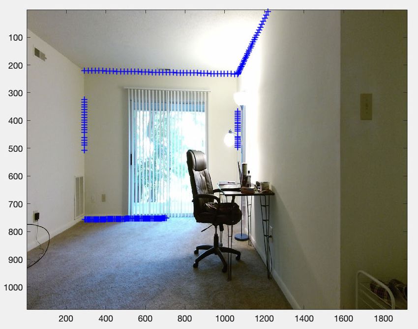
FIGURE 6. Annotated endpoints of small 2D line segments are visualized
B. CANDIDATE LAYOUT ESTIMATION IN THE KEYFRAMES as white ‘+’ signs in three manually-selected keyframes (best viewed in
color). These endpoints are annotated in pairs. Notice these annotations
We estimate the initial layout on these partially-annotated are unlabeled, i.e., it is not known whether a line associated with a pair is
keyframes by extending the 2D line segments until they reach vertical or horizontal. RGB (left) and depth (right) images are shown for
either the boundary of the image or a visible intersection (e.g., each keyframe in each row.
corner point in the room). We then find the 2D line equations
associated with each 2D line-segment in image space and then
find all pairs of intersections between these 2D lines as our C. LAYOUT PROPAGATION FROM THE
initial hypothesis of the layout. Then for each line segment, CANDIDATE LAYOUTS
we extend it both directions to find the intersection that is The scene layout for each of these keyframes, represented as
closest to the line. Since the depth channel is very noisy 3D lines, are projected into unlabeled contiguous frames in an
and a portion of the space has missing depth information, interactive process. The projections of these multiple layouts
we need to infer missing 3D points and, as a consequence, are typically not aligned due to camera pose estimation errors
our algorithm needs to move back and forth from the 2D in the new frame. To address this problem, we first perform
line equation to the 3D line equation. Once the layouts are some data association steps on individual 3D lines. Then,
estimated in the keyframes, we transfer these layouts to the the final layout is estimated by reasoning on 3D line to line
rest of the frames using the camera poses and 3D point clouds. intersections on these resulting data associations.
VOLUME 8, 2020 7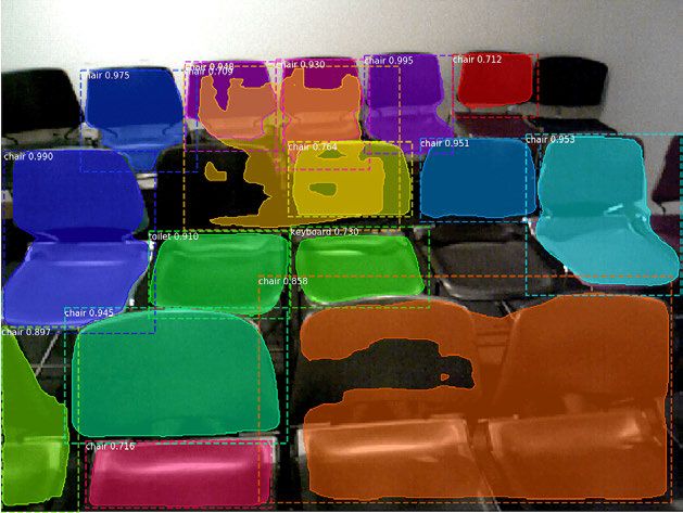
M. A. Reza et al.: Automatic Dense Annotation for Monocular 3D Scene Understanding

    FIGURE 7. Initial layout in three keyframes from the 2D point manual annotations. The points corresponds to vertical 3D lines projected in 2D
    image space.

   In more detail, the process for generating the final layout                    We then adopted a similar data association approach in
is described in the following several steps.                                   finding the final set of horizontal 3D lines. Vertical lines,
                                                                               in general, follow an orientation that is towards the gravity
1) VERTICAL 3D LINE ASSOCIATION                                                direction in an indoor scene, e.g., vertical edges of a door,
The vertical 3D lines that form the initial layout in all the                  vertical edges of a window, edges in between two wall inter-
annotated keyframes are transferred to the target frame for                    sections, etc. Unlike the vertical 3D lines, the horizontal 3D
which we need to estimate the scene layout. The 3D points                      lines are oriented in several directions. We split the horizontal
associated with these vertical 3D lines are projected into the                 3D lines data association in two steps instead of directly asso-
current frame’s camera coordinate space using the world-to-                    ciating them. First, we separate the horizontal 3D lines based
camera transformation matrix.                                                  on their orientation so that those 3D lines that are oriented
   To do this, we first find the groups of vertical 3D lines that              towards the same direction are grouped together. Second,
are close to each other. We construct a graph G = (V , E), with                we take all the horizontal 3D lines in each orientation-group
a vertex associated with each 3D line. We add an edge in this                  in turn, and then follow a 3D distance (from one line to
graph if one 3D line is reachable from another. More pre-                      another) based association as used in the vertical 3D line data
cisely, we compute a form of adjacency matrix in this graph                    association.
which we refer to as the reachable matrix, R3d . Whether a                        To illustrate the process, assume that the horizontal 3D
line is reachable from another is decided based on the average                 lines are oriented towards either the Z-axis or the X-axis in the
distance between the two lines. For example, we compute the                    current frame’s camera coordinate space. Our algorithm sep-
distance (in 3D) from 3D line li to 3D line lj and vice versa.                 arates the horizontal 3D lines in two different groups based
If these two distances are within a threshold, we set R3d ij to 1,
                                                                               on their orientations in the scene. To separate the horizontal
and otherwise set it to 0.                                                     3D lines based on their orientations, we adopt a similar graph
   Once the reachable matrix R3d is computed, we find the                      construction procedure as is used in the vertical 3D line asso-
connected components on the graph G. Each component                            ciation. For computing the edges in the graph G = (V , E) that
represents the set of 3D lines that corresponds to the same 3D                 encode adjacency information between the lines, we compute
line coming from the annotated keyframes. We accumulate                        the angular similarity instead of 3D distance between the
all the 3D points associated with each 3D line in a group,                     lines. We compute a form of adjacency matrix in this graph
and then estimate a single 3D line from these accumulated                      which we refer to as H angular . Once H angular is computed,
3D points using a RANSAC-based line fitting algorithm. The                     we find the connected components from this matrix using
same process is repeated for all the components in the graph                   a Depth First Search (DFS). Each component identifies the
G. This data association step allows us to find a final set of 3D              set of horizontal 3D lines that are oriented towards the same
vertical lines, which is subsequently used to form the final                   direction.
layout.                                                                           For all the horizontal 3D lines in a single connected compo-
                                                                               nent, we associate them using a 3D distance-based data asso-
2) HORIZONTAL 3D LINE ASSOCIATION                                              ciation as used in our vertical data association. Assume there
Similar to the vertical case, the horizontal 3D lines that form                are M connected components. We construct a set of adjacency
the initial layout in all the annotated keyframes are also                     matrices {H13d , H23d , . . . , HM
                                                                                                                3d }, where each H 3d represents
                                                                                                                                  k
transferred to the current frame. The 3D points associated                     the adjacency matrix for the 3D distance-based horizontal
with these horizontal 3D lines are projected into the current                  3D line association. For each Hk3d , we again compute the
frame’s camera coordinate space using the world-to-camera                      connected component, where each component represents all
transformation matrix.                                                         the annotated horizontal 3D lines that come from different

8                                                                                                                                          VOLUME 8, 2020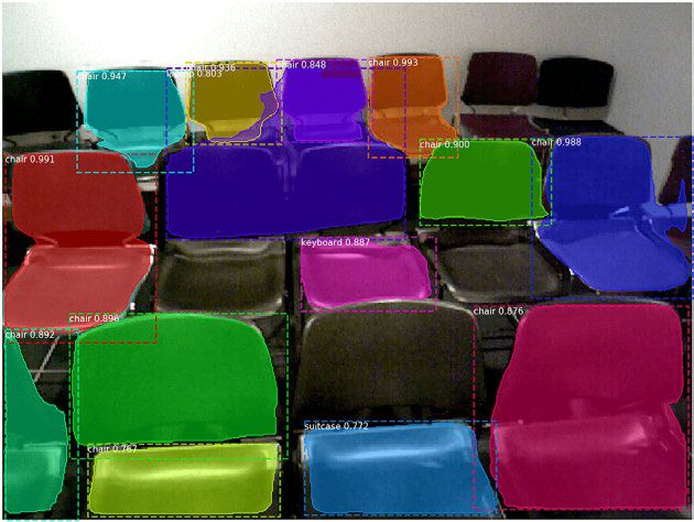
M. A. Reza et al.: Automatic Dense Annotation for Monocular 3D Scene Understanding

          FIGURE 8. The process of the horizontal 3D lines association in a given frame (best viewed in color). The horizontal lines are shown
          in a bird-eye view in two different XZ planes: i) ceiling XZ plane (in blue color) and ii) floor XZ plane (in green color). (a) shows the
          original RGB image of a frame, (b) shows all the horizontal lines before they are associated together. In the left panel, blue represents
          the horizontal lines on the ceiling XZ plane, and in the right panel, green denotes the horizontal line on the floor XZ plane, and (c) a
          set of lines each fitted with RANSAC.

keyframes. Like the vertical 3D line data association method,                    Figure 9(a)). For each intersection of a pair of horizontal lines,
we accumulate all the 3D points associated with each hori-                       we find the closest vertical junctures. These vertical junctures
zontal 3D line in a component computed from Hk3d . We esti-                      act as boundaries for horizontal lines to limit their extensions.
mate a single 3D line from these accumulated 3D points using                     We extend each horizontal line until its boundary limits if
a RANSAC-based line fitting algorithm. We execute our                            both ends of the line have associated vertical junctures. If any
horizontal 3D line association in the two XZ planes: a) ceiling                  side of a horizontal line is not limited by a vertical juncture,
XZ plane and b) floor XZ plane separately. We determine this                     then we extend that horizontal line until it reaches the image
partitioning of horizontal 3D lines based on distance offset.                    boundary.
Figure 8(a) shows a sample frame in question in which we                            Similarly, we project the 3D horizontal lines pertaining
want to propagate the layout. Figure 8(b) shows the horizontal                   to the floor on the XZ plane as shown in Figure 9(c), and
3D lines projected on the ceiling XZ plane (left) and on the                     then trace their boundaries as shown in Figure 9(d). Once
floor XZ plane (right). Finally, Figure 8(c) shows the set of                    we have the extensions of the horizontal lines in both floor
RANSAC-fitted lines after the data association.                                  and ceiling XZ planes, we render their projections in the 2D
   These fitted horizontal lines – in conjunction with the                       image space to define the final layout. The vertical lines are
fitted vertical lines – are used to estimate the final scene                     extended in both directions until they reach the ceiling and
layout for the current frame. One advantage of partitioning                      the floor. Figure 9 illustrates these steps of the final layout
the horizontal lines using orientation first is that it permits                  estimation.
our algorithm to estimate the layout for a scene with arbitrary
shapes. In other words, our algorithm is not restricted to
environments that follow the ‘‘Manhattan-World’’ assump-                         V. EXPERIMENTS
tion that the planes in a scene are oriented towards one of                      A. SEMANTIC LABEL GENERATION
the three orthogonal vanishing directions: our algorithm can                     We experimented on the eight RGB-D video sequences
find the layout for a more general rooms layouts including                       from SUN3D [34] to validate our automatic annotation
pentagonal, hexagonal, etc.                                                      approach. Table 2 shows statistics for the eight video
                                                                                 sequences. Each video consists of thousands of frames cap-
3) COMBINE THE 3D LINES FOR FINAL                                                tured across various indoor locations in university campuses
LAYOUT ESTIMATION                                                                and dormitories. Only a fraction of these frames have been
Once we find the set of RANSAC-fitted horizontal and verti-                      manually annotated. We validate the automatically generated
cal 3D lines in the current frame’s camera coordinate space,                     annotations from our approach on these frames.
we combine them to estimate our final scene layout for the                          We used 10 categories, including both fine-grained (Bed,
frame. We trace extensions of the layout in the ceiling XZ                       Chair, Table, TV, Floor, Ceiling) and generic categories
plane and the floor XZ plane separately. The steps of find-                      (Props, Furniture, Structure). We conform to this selection
ing boundaries of the layout in the ceiling XZ plane are as                      based on the labeling criteria laid out by the popular indoor
follows. First, we project the 3D horizontal lines pertaining                    scene understanding dataset NYUD-V2 [45].
to the ceiling on the XZ plane as shown in Figure 9(a).                             We used an open-source implementation of Mask-
Then, we project all the vertical 3D lines in the XZ plane.                      RCNN [46] pretrained on MS COCO [47] as our object
We find the mean of these projected vertical lines (shown by                     detector. MS COCO consists of 80 categories commonly
the red dots in Figure 9(a)). We refer to these points as vertical               found in both indoor and outdoor scenes; we selected only
junctures.                                                                       the indoor object categories. We mapped categories of MS
   We also compute all pairs of intersections among the                          COCO to categories used in our experiments, as shown in
projected lines in the XZ plane (shown by the blue dots in                       Table 5.

VOLUME 8, 2020                                                                                                                                        9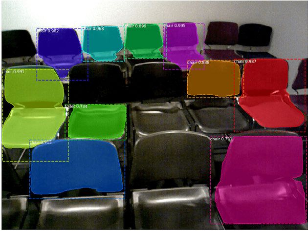
M. A. Reza et al.: Automatic Dense Annotation for Monocular 3D Scene Understanding

           FIGURE 9. An illustrative example of the final layout estimation (best viewed in color). (a) Projection of the horizontal lines in the
           ceiling XZ plane. (b) Projected 2D points of the estimated ceiling boundaries of the layout. (c) Projection of the horizontal lines in
           the floor XZ plane. (d) Projected 2D points of the estimated layout floor boundaries also augmented in the image space. (e) Final
           layout including the vertical lines that are extended until they reach both XZ planes (ceiling and floor).

TABLE 2. Statistics of 8 video sequences in SUN3D [34]

   For 3D scene layout estimation, we used the implementa-
tion by the author of [39]. The estimated layout provides a
single mask for floor and ceiling categories, and the remain-
ing layout is represented as series of other masks such as
Wall, Office-partition, Door, etc. We map these categories to
a generic Structure category as in NYUD-V2 [45].
   To measure the performance of our automatic annotation,
we used two metrics: per-class accuracy: for each class, find
the proportion of correctly-labeled pixels, and per-class IoU:
for each class, compute the ratio of the size of the intersection
of ground truth label and estimated label regions, and the size
of the union between the ground truth and estimated label.

1) AUTOMATIC ANNOTATION RESULTS
We validated the annotations generated automatically by our
method against the ground truth labels manually prepared by
a human in each video sequence. As the manual annotation
is laborious and expensive, each video sequence has only
a small fraction of the frames manually labeled (as shown
in Table 2). This is exactly the motivation for our work: we                     FIGURE 10. Qualitative results for automatic annotation experiment on
can generate automatic annotations for all the frames in a                       different video sequences from SUN3D [34]. From left to right we show
                                                                                 the RGB image, the ground truth, and the automatic annotations from our
video sequence, allowing a larger quantity of annotations with                   method.
minimal human effort.
   The results of our evaluation using the two metrics defined
above are shown in Table 1. The table evaluates for each                            Our automatic annotation method performs well on object
individual category as well as the average across categories                     categories such as Chair, Table, and Bed, presumably because
(last column). To evaluate the category specific performance                     Mask-RCNN trained on MS COCO [47] has modeled these
across all the videos, we also report an aggregated mean in                      categories well. Some qualitative visualizations are shown
the last row. Each entry in the table lists two numbers: per-                    in Figure 10. As we notice, our method can reliably annotate
class accuracy and per-class IoU. A missing entry signifies                      chair, table, bed categories in most cases. Our method had
that the object is not present in that video (e.g., TV is present                weaker performance on the generic object categories such
only in hotel-umd).                                                              as Props and Furniture. Our method solely relies on the

10                                                                                                                                            VOLUME 8, 2020
M. A. Reza et al.: Automatic Dense Annotation for Monocular 3D Scene Understanding
TABLE 3. Semantic segmentation performance comparison. First and second items in each table entry denote metrics average per-class and average IoU
respectively. Last column shows the aggregated performance across all 8 classes
TABLE 4. Videos used in our experiments from Active Vision Dataset [33]
FIGURE 11. Qualitative comparison for semantic segmentation on the
images on test set (left) when trained on human annotated (middle) vs
automatic annotated (right).
Figure 11. The average per-class accuracy for GT is 56.4%
and average IoU accuracy is 42.0%. The average per-class
accuracy of the model Auto is 35.1% and average IoU accu-
signals from our object detectors to capture the annotation racy is 20.1%. Of course, this is to be expected: GT was
information; when a detector consistently fails to detect an trained on laboriously hand-labeled training data, whereas
object across a video sequence, our method fails to annotate Auto required no human annotation whatsoever. Auto per-
that object. Our method also captures the annotations for forms well on categories such as chair, floor, structure and
Floor and Structure categories since our layout estimation table, although not as well as the GT model. Additionally,
can retrieve the structure of almost all of the scenes from the we observe that both models do not perform well on cat-
RGB-D images. egories such as furniture and props, as SUN3D has very
few instances of these categories, making it difficult for the
2) SEMANTIC SEGMENTATION WITH AUTOMATIC segmentation network to learn a reasonable model even with
ANNOTATIONS perfect ground truth annotations.
Since our goal is to generate automatic annotations that would To further understand the effectiveness of our
be useful for training deep semantic segmentation models, automatically-generated annotation, we trained another
we evaluated our technique as a means of generating ground model, GT + Auto-sample (last row in Table 3), by adding
truth labels for FCN [2] for the 10 object categories men- more samples of automatically-annotated frames to the exist-
tioned above. We partitioned the 8 videos of SUN3D into ing 264 human-annotated training frames. More specifically,
4 for training and 4 for testing. The training video sequences Auto-sample was prepared by sampling the automatic anno-
include hotel-umd, hv-c5, studyroom, mit-32 which have a tation of every 15-th image in each training video, resulting
total of 264 human-annotated keyframes. Our test partition, in a total of 838 automatic annotated frames. Although
hv-c6, hv-c8, dorm, mit-lab, has 131 human-annotated frames the overall performance of GT + Auto-sample is inferior
in total. We use all the 264 training frames along with their compared to GT (average per-class and IoU are 48.5% and
ground truth labels to train a FCN model, which we refer to 30.0% respectively), we observe performance improvements
as GT. We then automatically generated annotations for these for some categories such as Chair, Table, and Floor. These
frames using our method, and used them to train another FCN three belong to the classes for which our automatic annotation
model, which we call Auto. Both models were trained for method performed well (as reported in Table 2 and also
60,000 iterations with learning rate 1e− 5 and cross-entropy discussed in Section V-A.1).
loss.
Quantitative results are shown in Table 3 (excluding TV B. VIDEO GEOMETRIC LABEL GENERATION RESULTS
which is absent in the test partition), with the first value We evaluated our semi-automatic geometric annotation algo-
in each entry indicating per-class accuracy and the second rithm primarily on the Active Vision Dataset (AVD) [33],
indicating IoU accuracy. Qualitative results are shown in which contains diverse indoor environment types across
VOLUME 8, 2020 11M. A. Reza et al.: Automatic Dense Annotation for Monocular 3D Scene Understanding
TABLE 5. Mapping of MS COCO [47] categories to indoor scene categories for our automatic annotation approach
FIGURE 12. Final estimated layout in three unannotated frames. The blue lines are vertical 3D lines projected in 2D image space, while the red
lines are similarly found vertical lines.
multiple geographic locations in the United States. Each room layout estimation, using minimal human interven-
video was captured by a camera mounted on a robot that tion. For semantic object segmentation, our method is fully-
was directed to roam through the rooms inside the apartment. automatic and relies on two complementary sources of
We experimented with 14 videos from AVD where each video evidence: pre-trained object detectors and rough scene
contains between approximately 700 and 2500 frames, for a layout estimators. For 3d room layout, we proposed a semi-
total of 18780 frames. Table 4 reports the detailed statistics automated technique that requires a human operator to pro-
of the videos that are used in our experiments. We per- vide just a few key annotations for a handful of keyframes
formed the manual point-level annotation for all 14 videos, of an RGBD video, and then the dense room layout is auto-
and so far have applied the annotation algorithm on ‘‘Home matically estimated and propagated across time to the unla-
001’’,‘‘Home 003’’, and ‘‘Home 011’’. We show sample final beled frames. These methods offer an alternative technique
layouts in some frames in Figure 12. for generating a large quantity of dense pixel-level annota-
Our algorithm is flexible and applicable to generate anno- tions for training data-hungry deep neural network models.
tations from other indoor data sources such as the SUN3D In the future, we plan to augment the method to generate
dataset [34] and the GMU Kitchen dataset [48]. There are annotations for a large number of fine-grained indoor object
8 videos in SUN3D dataset containing 19243 frames in categories. We also plan to explore the feasibility of our
total, and it is a suitable a dataset for our semi-automatic approach in the outdoor setting.
annotation algorithm. GMU Kitchen contains 6735 frames
from 9 videos. These videos from SUN3D and GMU kitchen ACKNOWLEDGMENT
datasets were captured in different types of indoor environ- Kai Chen participated in this project while visiting Indi-
ments ranging from apartment, classroom, and office, and ana University through the IU Global Talent Attraction Pro-
thus could be additional sources of training data generation gram (GTAP) program. All work was conducted while the
using our algorithm. authors were at Indiana University.
VI. CONCLUSION
REFERENCES
In this work, we presented a method for generating anno-
[1] A. Anzai and G. C. DeAngelis, ‘‘Neural computations underlying depth
tations for creating training data for two indoor scene perception,’’ Current Opinion Neurobiol., vol. 20, no. 3, pp. 367–375,
understanding tasks, semantic object segmentation and 3d Jun. 2010.
12 VOLUME 8, 2020M. A. Reza et al.: Automatic Dense Annotation for Monocular 3D Scene Understanding
[2] J. Long, E. Shelhamer, and T. Darrell, ‘‘Fully convolutional networks [26] C. Zou, A. Colburn, Q. Shan, and D. Hoiem, ‘‘LayoutNet:
for semantic segmentation,’’ in Proc. IEEE Conf. Comput. Vis. Pattern Reconstructing the 3D room layout from a single RGB image,’’ in
Recognit. (CVPR), Jun. 2015, pp. 3431–3440. Proc. IEEE/CVF Conf. Comput. Vis. Pattern Recognit., Jun. 2018,
[3] V. Badrinarayanan, A. Kendall, and R. Cipolla, ‘‘SegNet: A deep convolu- pp. 2051–2059.
tional encoder-decoder architecture for image segmentation,’’ IEEE Trans. [27] C.-Y. Lee, V. Badrinarayanan, T. Malisiewicz, and A. Rabinovich, ‘‘Room-
Pattern Anal. Mach. Intell., vol. 39, no. 12, pp. 2481–2495, Dec. 2017. Net: End-to-End room layout estimation,’’ in Proc. IEEE Int. Conf. Com-
[4] L.-C. Chen, G. Papandreou, I. Kokkinos, K. Murphy, and A. L. Yuille, put. Vis. (ICCV), Oct. 2017, pp. 4875–4884.
‘‘DeepLab: Semantic image segmentation with deep convolutional nets, [28] J. Huang, Y. Zhou, T. Funkhouser, and L. Guibas, ‘‘FrameNet: Learning
atrous convolution, and fully connected CRFs,’’ IEEE Trans. Pattern Anal. local canonical frames of 3D surfaces from a single RGB image,’’ 2019,
Mach. Intell., vol. 40, no. 4, pp. 834–848, Apr. 2018. arXiv:1903.12305. [Online]. Available: http://arxiv.org/abs/1903.12305
[5] C. Liu, K. Kim, J. Gu, Y. Furukawa, and J. Kautz, ‘‘PlaneRCNN: 3D plane [29] S. Dasgupta, K. Fang, K. Chen, and S. Savarese, ‘‘DeLay: Robust spa-
detection and reconstruction from a single image,’’ in Proc. IEEE/CVF tial layout estimation for cluttered indoor scenes,’’ in Proc. IEEE Conf.
Conf. Comput. Vis. Pattern Recognit. (CVPR), Jun. 2019, pp. 4450–4459. Comput. Vis. Pattern Recognit. (CVPR), Jun. 2016, pp. 616–624.
[6] X. Sun, J. Wu, X. Zhang, Z. Zhang, C. Zhang, T. Xue, J. B. Tenenbaum, and [30] C. Liu, J. Yang, D. Ceylan, E. Yumer, and Y. Furukawa, ‘‘PlaneNet: Piece-
W. T. Freeman, ‘‘Pix3D: Dataset and methods for single-image 3D shape wise planar reconstruction from a single RGB image,’’ in Proc. IEEE/CVF
modeling,’’ in Proc. IEEE/CVF Conf. Comput. Vis. Pattern Recognit., Conf. Comput. Vis. Pattern Recognit., Jun. 2018, pp. 2579–2588.
Jun. 2018, pp. 2974–2983. [31] L. Yi et al., ‘‘Large-scale 3D shape reconstruction and segmentation
[7] N. Wang, Y. Zhang, Z. Li, Y. Fu, W. Liu, and Y.-G. Jiang, ‘‘Pixel2mesh: from ShapeNet Core55,’’ 2017, arXiv:1710.06104. [Online]. Available:
Generating 3d mesh models from single rgb images,’’ in Proc. Eur. Conf. http://arxiv.org/abs/1710.06104
Comput. Vis. (ECCV), 2018, pp. 52–67. [32] A. X. Chang, T. Funkhouser, L. Guibas, P. Hanrahan, Q. Huang, Z. Li,
[8] A. Mallya and S. Lazebnik, ‘‘Learning informative edge maps for indoor S. Savarese, M. Savva, S. Song, H. Su, J. Xiao, L. Yi, and F. Yu, ‘‘ShapeNet:
scene layout prediction,’’ in Proc. IEEE Int. Conf. Comput. Vis. (ICCV), An information-rich 3D model repository,’’ 2015, arXiv:1512.03012.
Dec. 2015, pp. 936–944. [Online]. Available: http://arxiv.org/abs/1512.03012
[9] H. Izadinia, Q. Shan, and S. M. Seitz, ‘‘IM2CAD,’’ in Proc. IEEE Conf. [33] P. Ammirato, P. Poirson, E. Park, J. Kosecka, and A. C. Berg,
Comput. Vis. Pattern Recognit. (CVPR), Jul. 2017, pp. 5134–5143. ‘‘A dataset for developing and benchmarking active vision,’’
[10] M. A. Reza, H. Zheng, G. Georgakis, and J. Kosecka, ‘‘Label propagation in Proc. IEEE Int. Conf. Robot. Autom. (ICRA), May 2017,
in RGB-D video,’’ in Proc. IEEE/RSJ Int. Conf. Intell. Robots Syst. (IROS), pp. 1378–1385.
Sep. 2017, pp. 4917–4922. [34] J. Xiao, A. Owens, and A. Torralba, ‘‘SUN3D: A database of big spaces
[11] V. Badrinarayanan, F. Galasso, and R. Cipolla, ‘‘Label propagation in reconstructed using SfM and object labels,’’ in Proc. IEEE Int. Conf.
video sequences,’’ in Proc. IEEE Comput. Soc. Conf. Comput. Vis. Pattern Comput. Vis., Dec. 2013, pp. 1625–1632.
Recognit., Jun. 2010, pp. 3265–3272. [35] O. Miksik, D. Munoz, J. A. Bagnell, and M. Hebert, ‘‘Efficient temporal
[12] S. Mustikovela, M. Yang, and C. Rother, ‘‘Can ground truth label propaga- consistency for streaming video scene analysis,’’ in Proc. IEEE Int. Conf.
tion from video help semantic segmentation?’’ in Proc. ECCV Workshop Robot. Autom., May 2013, pp. 133–139.
Video Segmentation, 2016, pp. 804–820. [36] A. Handa, V. Patraucean, V. Badrinarayanan, S. Stent, and R. Cipolla,
[13] K. He, G. Gkioxari, P. Dollar, and R. Girshick, ‘‘Mask R-CNN,’’ in Proc. ‘‘Understanding RealWorld indoor scenes with synthetic data,’’ in
IEEE Int. Conf. Comput. Vis. (ICCV), Oct. 2017, pp. 2961–2969. Proc. IEEE Conf. Comput. Vis. Pattern Recognit. (CVPR), Jun. 2016,
[14] M. A. Reza, A. U. Naik, K. Chen, and D. J. Crandall, ‘‘Automatic annota- pp. 4077–4085.
tion for semantic segmentation in indoor scenes,’’ in Proc. IEEE/RSJ Int. [37] S. Richter, V. Vineet, S. Roth, and V. Koltun, ‘‘Playing for data: Ground
Conf. Intell. Robots Syst. (IROS), Nov. 2019, pp. 4970–4976. truth from computer games,’’ in Proc. Eur. Conf. Comput. Vis., 2016,
[15] S. Gupta, P. Arbelaez, and J. Malik, ‘‘Perceptual organization and recogni- pp. 108–112.
tion of indoor scenes from RGB-D images,’’ in Proc. IEEE Conf. Comput. [38] S. Tsutsui, Y. Fu, and D. Crandall, ‘‘Meta-reinforced synthetic data for one-
Vis. Pattern Recognit., Jun. 2013, pp. 564–574. shot fine-grained visual recognition,’’ in Proc. Adv. Neural Inf. Process.
[16] N. Dong and E. Xing, ‘‘Few-shot semantic segmentation with prototype Syst. (NIPS), 2019, pp. 3057–3066.
learning,’’ in Proc. Brit. Mach. Vis. Conf., 2018, pp. 1–5. [39] C. Taylor and A. Cowley, ‘‘Parsing indoor scenes using RGB-D imagery,’’
[17] W. Liu, D. Anguelov, D. Erhan, C. Szegedy, S. Reed, C. Fu, and A. Berg, in Proc. Robot. Sci. Syst. (RSS), 2012, pp. 401–408.
‘‘SSD: Single shot multibox detector,’’ in Proc. Eur. Conf. Comput. Vis., [40] P. F. Felzenszwalb and D. P. Huttenlocher, ‘‘Efficient graph-based
2016, pp. 21–37. image segmentation,’’ Int. J. Comput. Vis., vol. 59, no. 2, pp. 167–181,
[18] J. Redmon and A. Farhadi, ‘‘YOLOv3: An incremental improve- Sep. 2004.
ment,’’ 2018, arXiv:1804.02767. [Online]. Available: http://arxiv.org/ [41] R. Achanta, A. Shaji, K. Smith, A. Lucchi, P. Fua, and S. Sässtrunk,
abs/1804.02767 ‘‘SLIC superpixels compared to state-of-the-art superpixel methods,’’
[19] L. Castrejon, K. Kundu, R. Urtasun, and S. Fidler, ‘‘Annotating object IEEE Trans. Pattern Anal. Mach. Intell., vol. 34, no. 11, pp. 2274–2282,
instances with a polygon-RNN,’’ in Proc. IEEE Conf. Comput. Vis. Pattern Nov. 2012.
Recognit. (CVPR), Jul. 2017, pp. 5230–5238. [42] P. Arbelaez, J. Pont-Tuset, J. Barron, F. Marques, and J. Malik, ‘‘Multi-
[20] M. Suchi, T. Patten, D. Fischinger, and M. Vincze, ‘‘EasyLabel: A semi- scale combinatorial grouping,’’ in Proc. IEEE Conf. Comput. Vis. Pattern
automatic pixel-wise object annotation tool for creating robotic RGB- Recognit., 2014, pp. 328–335.
D datasets,’’ in Proc. Int. Conf. Robot. Autom. (ICRA), May 2019, [43] Y. Boykov, O. Veksler, and R. Zabih, ‘‘Fast approximate energy minimiza-
pp. 6678–6684. tion via graph cuts,’’ IEEE Trans. Pattern Anal. Mach. Intell., vol. 23,
[21] P. Marion, P. R. Florence, L. Manuelli, and R. Tedrake, ‘‘Label fusion: no. 11, pp. 1222–1239, Sep. 2001.
A pipeline for generating ground truth labels for real RGBD data of clut- [44] J. L. Schonberger and J.-M. Frahm, ‘‘Structure-from-motion revisited,’’
tered scenes,’’ in Proc. IEEE Int. Conf. Robot. Autom. (ICRA), May 2018, in Proc. IEEE Conf. Comput. Vis. Pattern Recognit. (CVPR), Jun. 2016,
pp. 1–8. pp. 4104–4113.
[22] J.-H. Lee, M. Heo, K.-R. Kim, and C.-S. Kim, ‘‘Single-image depth [45] N. Silberman, D. Hoiem, P. Kohli, and R. Fergus, ‘‘Indoor segmentation
estimation based on Fourier domain analysis,’’ in Proc. IEEE/CVF Conf. and support inference from RGBD images,’’ in Proc. Eur. Conf. Comput.
Comput. Vis. Pattern Recognit., Jun. 2018, pp. 330–339. Vis., 2012, pp. 746–760.
[23] R. Zhao, Y. Wang, and A. M. Martinez, ‘‘A simple, fast and highly-accurate [46] W. Abdulla, ‘‘Mask R-CNN for object detection and instance segmentation
algorithm to recover 3D shape from 2D landmarks on a single image,’’ on Keras and TensorFlow,’’ GitHub Repository, 2017. [Online]. Available:
IEEE Trans. Pattern Anal. Mach. Intell., vol. 40, no. 12, pp. 3059–3066, https://github.com/matterport/Mask_RCNN
Dec. 2018. [47] T.-Y. Lin, M. Maire, S. Belongie, L. Bourdev, R. Girshick, J. Hays,
[24] I. Laina, C. Rupprecht, V. Belagiannis, F. Tombari, and N. Navab, ‘‘Deeper P. Perona, D. Ramanan, C. Lawrence Zitnick, and P. Dollár, ‘‘Microsoft
depth prediction with fully convolutional residual networks,’’ in Proc. 4th COCO: Common objects in context,’’ 2014, arXiv:1405.0312. [Online].
Int. Conf. 3D Vis. (3DV), Oct. 2016, pp. 239–248. Available: http://arxiv.org/abs/1405.0312
[25] L. Roberts, ‘‘Machine perception of three-dimensional solids,’’ Ph.D. dis- [48] G. Georgakis, M. A. Reza, A. Mousavian, P.-H. Le, and J. Kosecka,
sertation, Dept. Elect. Eng., Massachusetts Inst. Technol., Cambridge, MA, ‘‘Multiview RGB-D dataset for object instance detection,’’ in Proc. 4th Int.
USA, 1961. Conf. 3D Vis. (3DV), Oct. 2016, pp. 426–434.
VOLUME 8, 2020 13You can also read