Best Practice Guidance - Type C Waterproofing Systems First Issued March 2015
←
→
Page content transcription
If your browser does not render page correctly, please read the page content below
Best
     Practice
     Guidance

        Type C
     Waterproofing
       Systems

         A SS O CI AT I O N

        First Issued March 2015

            Supported by

Visit www.property-care.org for more documents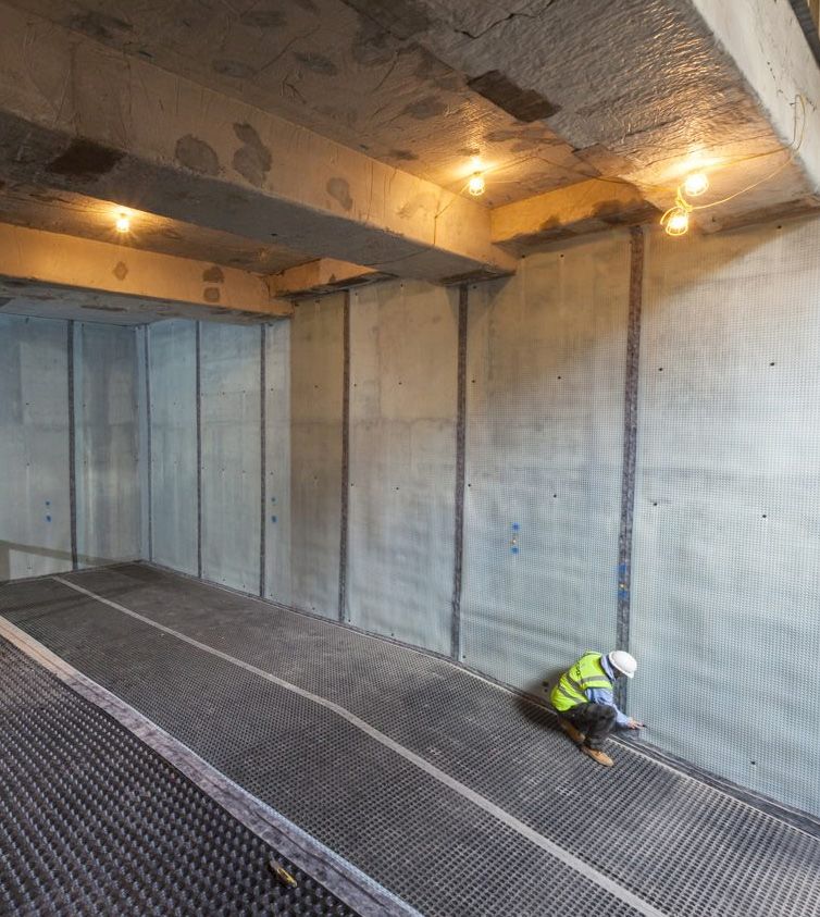
Best Practice Guidance - Type C Waterproofing Systems
    (BS8102: 2009)
    1. Introduction                                9. Service and maintenance of cavity
    		 1.1. Appropriate Areas of Use               drainage waterproofing systems
    		 1.2. Basement site locations and forms
    		 1.3. Combination Systems                    10. Standards and codes
    2. Definitions
                                                   11.	Warranties, guarantees and
    3. Principles of Design                             insurance
    		 3.1. BS8102: 2009
    		 3.2. Design and Build Philosophy            12. Training / supervision
    		 3.3. Designer
    		 3.4. Installer                              13. Bibliography
    		 3.5. Site Investigation
    			       3.5.1. Risk Assessment               14. Acknowledgements
    			       3.5.2. Water table
    			       3.5.3. Ground conditions
    			       3.5.4. Ground drainage
    			       3.5.5. Soil type and conditions
    		 3.6. Sequence and timing of work
    		 3.7. Considerations
    			       3.7.1. Site de-watering
    			       3.7.2. Ground gases
    			       3.7.3. Existing Structures
    		 3.8. Structural stability

    4. Products
    		 4.1. Cavity Drainage membranes
    		 4.2. Floor Drainage Channels
    		 4.3. Ancillary products
    			       4.3.1. Pump Systems
    			       4.3.2. Battery Back-up systems
    		 4.4. Product Selection

    5. 	Cavity drainage membrane
         application, fitting and detailing etc.
    		 5.1. Applications on Floors
    		 5.2. Accommodating Services
    		 5.3. C
             ontinuity with other systems
            and trades

    6. Insulation in basements

    7.	Issues of ‘free lime’ in cavity
        drainage systems

    8. Defects, repairs and maintenance

2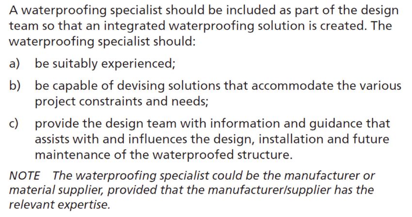
1. INTRODUCTION
This document has been produced to provide guidance on the design, adoption and use of Type C
waterproofing in below ground structures.

Type C (drained) protection is defined by BS8102: 2009 (Code of practice for protection of below ground
structures against water from the ground) as where the structure itself provides primary resistance against
WATER penetration and incorporates a drained cavity within the basement structure. There is permanent
reliance on this cavity to collect groundwater seepage through the structure and direct it to drains or a sump
for removal by drainage or pumping.

The external basement wall must provide enough PRIMARY resistance to water ingress to ensure the cavity
accepts only a controlled amount of water or dampness.

Type C systems do not provide a hydrostatic barrier but provide protection by means of water management.

Characteristics of the types of waterproofing protection.

Theoretically any structural waterproofing membrane designed to resist a hydrostatic head should not let any
free water pass through it. However, in practice, consideration must always be given to what would happen
as a result of any defect. The effects of water table conditions on the three basement types are discussed
below. Where the site drains well enough to prevent the build-up of hydrostatic water pressure, all three forms
of construction carry little risk of water penetration. The designer will need to be very sure that no risk of rising
water is possible and it is much safer to always assume a full head of water pressure.

Type C construction relies on water being resisted by the structural elements and any water that penetrates
the external shell of the structure being collected in a cavity formed between the external wall and an internal
lining/wall. There is permanent reliance on this cavity to collect groundwater seepage and direct it to a suitable
discharge point, e.g. drains or a sump for removal by gravity drainage or mechanical pumping. The amount of
free water entering the cavity will depend on the size of the structure, on the volume of external water and its
hydrostatic pressure, and on the resistance of the structure itself to water ingress.

Designers need to consider any risk associated with a constant supply of possibly contaminated water to the
structure.

Such systems typically remove water via a mechanical sump pump system, or occasionally by gravity to low
ground or drains externally where properties are formed into sloping sites. A third option is to use pumped back-
flow protection devices where connection to drains is not safe. However, the need to control ground gases,
e.g. radon, may not allow the use of gravity drainage. In all cases, consideration should be given to the point at
which water discharges, understanding that the effectiveness of the system is reliant on removal of water, so
an appraisal of this factor is required. Type C pumped systems should be engineered to cope with worst-case
water ingress. If drainage capacity is exceeded, this may result in dampness or flooding. Type C systems are
only designed to control and manage MINOR leakage and seepage into a structure.

Type C is not typically designed in new structures to be the primary form of waterproofing. The structure is built
to be water resistant Type B, or is made to be water resistant by the application of Type A waterproofing. Type C
is installed as the maintainable serviceable water management element to deal with water ingress in the event
of a leak. If the new structure is leaking then defects should be rectified prior to the installation of the Type C
system.

Where Type C is used in a remedial or flooding situation and where water ingress cannot be stopped the
designer MUST provide a design to reduce the ingress as much as possible and calculate the maximum
potential flow rate of water given all of the known factors. (Structure, hydrology, historic ingress) and design the
drainage so the duty pumps and channel can manage the known volume of water. Back-up systems should
have the same capacity as the duty pumps and both should have suitable battery or generator back-ups.
Blockage of the cavity by silt or lime or other contaminants could result in flooding. The design of the system

                                                                                                                        3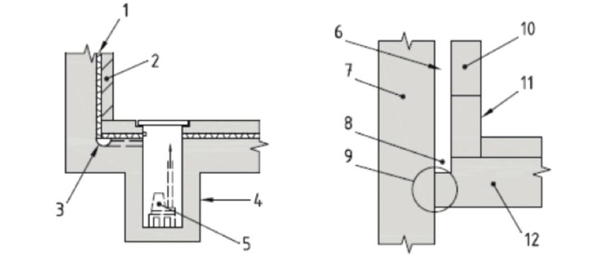
should allow for clearing of silt should blockages occur in the system including discharging drains. This will
    require accessible drainage that includes access/inspection ports (see chapter on drainage below.

    Where after careful consideration the preferred method is to discharge directly from a cavity drainage
    membrane to a discharge point, via perimeter channel, a risk assessment should be carried out. Collected
    water from cavity drainage membranes and channels should NEVER discharge directly into a combined
    sewer without correct approval and using appropriate non-return valves. Maintenance should be undertaken
    by a specialist, making assessment of the requirement to upgrade and replace pumps as necessary.

    When combining systems in order to minimise the risks or negate the need for remedial measures,
    consideration should be given to the compatibility of the combined systems.

    Type C = Drained protection - non-pressurised managed system using cavity drained membrane (CDM)
    directing water to drainage sump or gravity.

    KEY
    1 Cavity drain membrane                           7 Reinforced concrete/steel pile or
    2 Inner skin (render, dry lining or brick or        diaphragm wall
        masonry walling, depending on system)         8 Drainage channel
    3 Maintainable drainage channel with pipe       9 W aterstop at junction to follow wall profile
        connection to suitable drainage point         10 Internal block wall
    4 S  ump formed in situ or pre-formed            11 Access point(s) to drainage
    5 Pump                                            12 Floor slab with integral protection and/or
    6 Cavity wall                                          added membrane (internal or external)

    1.1. Appropriate areas of use.
    Although generally referred to when looking at designing basement waterproofing, Type C systems can be
    utilised for a number of earth-retained structures including:
       •    New build basements
       •    Basement refurbishment
       •    Semi basements and LGF areas
       •    Storage or plant rooms
       •    Any new Underground Structures
       •    Car parks
       •    Retaining walls
       •    Tunnels

    1.2. Basement site locations and forms
    There are many potential basement locations. Design forms and waterproofing methods will therefore depend
    on, for example, the prevailing terrain, soil conditions, water tables, proximity of adjacent buildings and
    the requirement of the end user. Typical locations and forms of basement construction are illustrated and
    summarised for three types of site: sloping, flat and infill.

4
Sloping sites
Sloping or elevated sites allow both full and semi-basements or split-level dwellings to be built, with cut-
and-fill options. Since these sites can normally be effectively drained, properties would be at less risk from
percolating groundwater and Type C systems may be used. However, the structure can pose a risk of
‘damming’ of water courses as the structure may also block the route of percolating water.
Flat sites
Flat sites provide the opportunity for basements wholly or partially below ground. Excavated material may be
reused to landscape around basements partially below ground, giving the dwelling an elevated aspect.
Basements constructed on a flat site in low-lying areas with impermeable soils can be difficult to drain. Where
there are problems with perched, fluctuating or permanently high water tables, substructures designed in
water-resistant Type B and Type C combination systems would therefore be advisable. Any window fire exit
must be above the highest anticipated water level. There is a greater risk of rising water to flat sites, and that
water, as it rises, develops water pressure. The risk of water ingress to flat sites is much greater due to rising
beds of water.
Additionally, while in the case of new construction waterproofing, the designer is providing the initial or first-
stage measures of protection against groundwater, in existing structures it is often the case that designs are
provided for the purpose of remedying failures in those initial measures, to address problems with systems of
considerable age in older or historic property, or to facilitate change of use.
If options are limited by the confines of the structure, it is important to understand what that structure is, and
equally, the nature of any installed waterproofing measures within it, which may further influence design.
Therefore, an analysis, through visual inspection, inspection of drawings (where available), and potentially
intrusive investigation, i.e. trial hole formation, should be undertaken so that a thorough understanding of the
structure and how it is constructed, is developed. The effects of any structural discontinuity as may typically
occur in an existing structure must also be assessed.
Once the structure is understood, and objectives and instructions are defined, it is the role of the
waterproofing designer to configure products and systems within that structure, all while considering the
appropriate factors detailed within this guide, so that the objectives are successfully met and structures are
protected in the long term.
1.3. Combination systems
Consideration should be given to the use of combined protection (i.e. Type A and Type B, Type A and Type C
or Type B and Type C) where in a single system:
• the assessed risks are deemed to be high;
• the consequences of failure to achieve the required internal environment are too high; or
• additional vapour checks are necessary for a system where unacceptable water vapour transmission
can occur. Although structures with Type B protection are designed to be water resistant, additional
waterproofing systems may be applied internally or externally to control water vapour movement,
where appropriate.
An in-situ “liner” wall designed to provide Type B protection can be cast inside an embedded retaining wall to
provide combined protection. In some cases, a fully bonded barrier might also be provided between the two
elements.
Although structures with Type C protection are designed to control and manage seepage into a structure,
where this is unacceptably high the water resistance of the structure should be improved prior to the
installation of the Type C protection, by the application of either Type A or Type B protection.
5When combining types of protection, the compatibility of the different protection types should be assessed in
order to minimize the risks and negate the need for remedial measures.
It is also important that any waterproofing works are correctly detailed to maintain continuity with above
ground works such as damp proof courses, damp proof membranes and cavity trays.
The design should ensure that waterproofing systems, materials and components are designed in
accordance with the manufacturer’s recommendations. Products used to create continuity are often loaded
by the upper outer structure and should be tested to ensure they are capable of resisting imposed load.
2. DEFINITIONS
For the purpose of this document, the following definitions refer:
TYPE A (BARRIER PROTECTION)
Protection against water ingress which is dependent on a separate barrier system applied to the structure.
TYPE B (STRUCTURALLY INTEGRAL PROTECTION)
Protection against water ingress `which is provided by the structure.
TYPE C (DRAINED PROTECTION)
Protection against water ingress into usable spaces which is provided by the incorporation of an appropriate
internal water management system.
CAPILLARY MOISTURE
Capillary moisture means moisture held in the capillaries of a material, and which exerts no hydrostatic
pressure on the structure.
CAVITY DRAINAGE MEMBRANE
Dimpled, flexible, high-density polymer sheet, which can be placed against the internal face of a structure
after construction and is designed to intercept water penetrating the structure and direct it to a drainage
system. CDM may need to be installed during construction where an internal wall is built - for example.
CE MARK
The CE mark, or formerly EC mark, is a mandatory conformity marking for certain products sold within the
European Economic Area (EEA) since 1985. The CE marking is also found on products sold outside the
EEA that are manufactured in, or designed to be sold in, the EEA.
GEOCOMPOSITE DRAINAGE MEMBRANE
Geocomposite membrane materials consisting of a high flow rate drainage core coupled on one or both
sides with filtering and/or impermeable elements to the other side.
HYDROSTATIC HEAD
Water pressure, expressed as an equivalent depth of water.
HYDROSTATIC PRESSURE
Water pressure exerted as a result of hydrostatic head. Pressure created by the volume of water.
INTERSTITIAL CONDENSATION
Interstitial condensation is condensation occurring to dewpoint surfaces that are WITHIN or between
building elements, as opposed to the more common surface condensation.
MEMBRANE
A barrier that is impervious to water.
6PLASTER
The term ‘plaster’ refers to any applied coat whose cementing action comes from either gypsum or cement/
lime.
PRESSURE
Pressure is a force per unit area applied in a direction perpendicular to the surface of an object e.g. water
pressure.
RENDER
The term ’render’ refers to any applied coating commonly made up of a sand and cement mix only which
can be used for coatings applied internally or externally. It may incorporate water-resisting admixtures,
accelerators, plasticisers, or other approved additives.
SEEPAGE
Slow transmission of water through discrete pathways of a structure.
STRESS
Stress is the reaction within the elements of a structure subjected to and resisting applied loads and/or
pressures.
TANKING
Application of an appropriate waterproofing barrier to the walls, the base slab and, where relevant, the roof
of a below ground structure, such that the entire envelope of the structure below ground is protected against
water ingress.
NOTE A cavity drain membrane is not considered to constitute tanking.
VAPOUR CHECK
Any layer that is very vapour impermeable and so significantly reduces the passage of water vapour.
VAPOUR CONTROL LAYER
A vapour control layer is a strategically placed vapour check, used where control of water vapour is needed.
VAPOUR RESISTANCE
The ability to resist water vapour.
WATER
Water is H2O in its liquid state.
WATERPROOF
A material or layer that is impervious to the passage of water.
WATERPROOFING
The application of a material that is impervious to water.
WATER RESISTANT
A material or layer with a high resistance to the passage of water.
WATER VAPOUR
Water in its gaseous phase.
73. PRINCIPLES OF DESIGN
3.1. BS8102: 2009
Code of Practice for the protection of below ground structures against water from the ground provides
provides guidance on the methods which can be adopted to deal with and prevent the entry of water
from the ground into a structure that is below ground level. It is widely referred to and used in basement
waterproofing, making particular reference to:
• Adoption of a design team
• Water table classification
• Defects and remedial measures
Design should be in accordance with relevant building regulations and applicable statutory requirements.
All elements (including foundations, walls and floors) forming a below ground structure requiring
waterproofing should be suitable for their intended purpose.
3.2. Design and Build Philosophy
As a general rule, design and construction should be kept as simple as possible. Consulting relevant
waterproofing design specialists as early as possible and working through details sequentially will help to
avoid unbuildable details on site.
All floors, ceilings and walls below external ground level including the junctions between them, should
be designed to resist the passage of water and depending on habitable grade, moisture to the internal
surface. The level of protection against water and moisture reaching the internal surfaces should be
appropriate for the proposed use.
Habitable accommodation should be designed to “Grade 3” as described in BS8102: 2009 – that ‘no water
penetration is acceptable and a dry environment will be provided if maintained by adequate ventilation’.
Plant rooms and storage should achieve Grade 2 as described in BS8102: 2009 as no water penetration
is acceptable although damp is tolerated. However consideration should be given to the type of plant and
stored items and their sensitivity to damp and any particular environmental controls required.
Car Parks can be grade 1 as described in BS8102: 2009 but consideration should be given to the present,
intended and possible future use of the car park area. The finishes required and the expectations of the
end user. Non-habitable areas such as parking areas can be designed to Grade 1 and are not normally
required to achieve Grade 2 level. Storage or plant rooms where the internal finishes are not readily
damaged by moisture should be designed to a minimum “Grade 2” as described in BS8102: 2009, as no
water penetration is acceptable, although damp is tolerated.
Retaining walls used to form elements such as light wells ideally could be designed to provide “Grade
1” protection”, however the client should be made fully aware of the limit to this level and whether this is
acceptable to the scheme.
3.3. Designer
Much of the failure associated with structural waterproofing is attributable to insufficient consideration of
the relevant factors, leading to poor design. It is therefore advisable that where specifying waterproofing,
these factors are examined rigorously, and that waterproofing specialists are consulted about a design at
the earliest stage.
8BS8102: 2009 defines:
Waterproofing systems should be designed by a Waterproofing Design Specialist who can demonstrate
that they have a suitable level of knowledge for designing waterproofing systems. Schemes offered by
bodies such as the NHBC and LABC have requirements for suitably qualified persons to be involved in the
design and installation of structural waterproofing systems. If a project is involves such a scheme it should be
determined if ANY qualifications are a requirement of any warranty application. In any case manufacturer’s
guidance and recommendations should be followed, unless any bespoke details have been confirmed with
them and other relevant parties.
The Property Care Association (PCA) provides training for surveyors and designers of underground
waterproofing systems. The Certificated Surveyor in Structural Waterproofing (CSSW) is a recognized
industry qualification which requires an understanding of waterproof systems and the ability to comment on
them. PCA has created a register of Waterproofing Design Specialists (WDS) who have shown further ability
to provide design advice for structural waterproofing. The list of Waterproofing Design Specialists can be
accessed – www.property-care.org/ProGuidance.RWDS.asp
3.4. Installer
Conditions of certification for waterproofing systems will usually require that they are installed ‘under license’
or by those trained by the supplier/manufacturer. ALL installations SHOULD be undertaken by suitably
trained operatives. This could be by operatives holding a relevant qualification in the application of structural
waterproofing, such as a relevant vocational qualification. Alternatively operatives trained and licensed by the
supplier/manufacturer or PCA training could also provide a suitable demonstration of skill and knowledge.
The designer and installation company should be able to demonstrate experience in the implementation of
similar waterproofing projects taking into account scale and complexity.
3.5. Site Investigation
An initial site investigation is important as its results will have a bearing not only on the waterproofing options
considered, but also how the structure is designed. Although the findings of a site investigation can be seen
as conclusive, consideration should be given that it is often a ‘snap shot in time’ and conditions on or around
the site may change in the future.
It should be assumed that water will come to bear against the full height of the below ground structure at
some stage in its life. Designing a system to offer full protection to full height, regardless of any water table
classification, should ALWAYS be considered.
3.5.1. Risk Assessment
A risk assessment should be carried out which identifies any possible long-term water pressures, the effects
of surface water percolation, use of external drainage and the effects of party wall impaction on neighbours.
It should take into consideration the possible effects of climate change, defective water goods, nearby
9trees, contaminants; and where external drainage is proposed, the effects dewatering may have on
adjacent structures along with the potential for silting of drainage.
3.5.2. Water Table
High water tables present the greatest risk of failure to the waterproofing of a basement and it is therefore
important to identify. A watercourse or water table that rises and falls and the potential for a perched water
table must also be identified. How often and for how long the water table stays high are also important
factors.
If the water table rises briefly – say, after heavy rain – and then immediately falls again, the risk of water
penetration through external waterproofing and then through the structure is less than if the water table
stays high for a much longer period. Consideration should also be given to the effect of possible planned
developments adjacent or in close proximity to the site either under consideration or potentially possible in the
future. Historic information on past flooding is valuable including any recording of rate of water ingress. Even
if the water table is variable IT IS ADVISABLE TO DESIGN TO THE “HIGHEST LEVEL”.
More information on water tables and ground water can be found in the PCA document ‘What is
groundwater?’
3.5.3. Ground Conditions
The design of the basement should take into account all current and likely future ground conditions.
A summary of common investigations relating to ground conditions along with some useful guidance is
given in the table below:
Investigations Guidance and information
Desk study including reviewing www.environment-agency.gov.uk/homeandleisure/floods
• groundwater and flooding issues www.bgs.ac.uk/research/groundwater/datainfo/levels/
• flood potential of the site home.html
• available groundwater data
www.metoffice.gov.uk/climate/uk/stationdata
• SuD’s impact assessment
• flood risk assessment TBIC - Guidance Documents (various)
• topography of the site PCA - ‘What is Groundwater?’
• effects of adjacent surface finishes
Testing required if there is the potential for chemically
Contaminated and aggressive ground
aggressive ground and/or groundwater
Seasonal water level change including risks of flash The report should consider likely fluctuations and short
flooding and water logging term flooding events that typically occur seasonally
Interpretative report by a qualified engineer or
hydrogeologists to include:
Assessment of impact on the ground water flow where the
• assessment of the direction of groundwater flow,
construction is likely to have a “damming” effect
• “Damming” effects on the groundwater regime,
• “Damming” effect of adjacent structures.
Contaminated Ground
It should be noted that whilst cavity drainage membranes may offer protection against the effects of Ground
Gases, this will depend on the results of soil investigation in conjunction with above and section 3.5.5.
103.5.4. Ground Drainage
The topography of the land and the direction and movement of any groundwater should be determined
as they will have a bearing on any proposals to provide drainage to reduce local groundwater pressures.
If there are any drains or land drains, their positions and performance should be established. Any new
construction proposals should not interrupt drains that still function unless measures are taken to redirect
them or to intercept the water by a new drainage system. Flat ground does not dewater. On sloping ground
the intercepted water courses should ALWAYS be directed around the obstructing structure to continue the
drainage path downhill.
3.5.5. Soil Type and Conditions
The type of soil can greatly influence the volume of water reaching the basement wall. Free-draining soils
not subject to variability in water tables generally present fewer problems than clays, which tend to be
impermeable.
It is important, therefore, to determine the soil type and, in particular, its drainage characteristics. It should
be noted that the soil around a basement may not be uniform and therefore care needs to be taken when
assessing its overall characteristics. Such assessment is best left to specialists.
Some soils contain chemicals that may harm both the structure and the waterproofing system. Check the
ground for materials that are detrimental, such as peat, sulphates, chlorides, VOCs and hydrocarbons and if
needed, implement an external barrier to protect the structure from these potential harmful chemicals.
BS8102: 2009 advises the designer to take account of the presence of, or potential for ground gases when
considering waterproofing. This is mentioned so that designers can take note of the perceived risks from
ground gases and advise their clients accordingly. It should also be noted that high levels of ground gases
can accumulate even where basements are protected by a waterproofing membrane (ground gas resistance),
and this may lead to the installation of a ground gas management system where the risk assessment,
particularly in existing structures, indicates that legislation might otherwise apply. See section 3.7.2 for more
information.
3.6. Sequence and Timing of Work
It is fundamental that the waterproofing elements of a structure are communicated with all relevant parties
throughout the construction process. For this reason the waterproof design should take into consideration
the construction stages and timing between them to ensure the end result and function of any installed
material is as expected. All parties should be aware of the waterproofing materials that are introduced at each
stage to avoid problematic post installations, miss-installations or potentially leaving them out altogether.
All waterproofing elements should be programmed into the construction programme and managed by
the designer or suitably experienced specialist installer. Problems occur on large projects due to a lack
of appreciation of the importance of waterproofing, site staff changes, inappropriate sequencing due to
programme pressures, lack of preparation, piecemeal waterproofing and failure to test and record installed
channels and bunds.
3.7. Considerations
3.7.1. Site De-Watering
If de-watering of a site is deemed necessary it should be done to a degree suitable for the proposed
system with due consideration to existing surrounding structures to ensure any potential movement to the
surrounding land as a result of de-watering does not have a detrimental effect. In any case specialist advice
should be sought. Suggested further points of reading regarding dewatering are:
• CIRIA Document 515. Groundwater control – Design and Practice
• Construction Dewatering and Groundwater Control: New Methods and Applications, 3rd Edition (J.
Patrick Powers, 2007)
• Groundwater Lowering in Construction: A Practical Guide (P.M. Cashman and Martin Preene, Ove
Arup & Partners, UK, 2001)
113.7.2. Ground Gases
The likelihood of gases can be established from the underlying geological structure, and guidance for its
control may be found in a number of documents and via official sources on the internet. BS8102: 2009
makes reference to maps of areas where basic or full protection against radon needs to be provided,
that are contained in the Building Research Establishment (BRE) reports BR211, BR376, BR413 and the
Health Protection Agency (HPA) documents:
• HPA-RPD-033, Indicative Atlas of Radon in England and Wales, 2007.
ISBN 978-0-85951-608-2, available from HPA.
• HPA-RPD-051, Radon in Dwellings in Scotland: 2008 Review and Atlas.
ISBN 978-0-85951-634-1, available from HPA.
• NRPB Documents, Vol 4, No.6, 1993, Radon affected areas: Scotland and Northern Ireland.
ISBN 085951367X, available from HPA.
Attention is also drawn to the Building Regulations, and to further guidance on the characterisation and
remediation of ground gases given in BS8485: 2015. Guidance on measures for large buildings is given
in BRE guidance Radon protection for new large buildings. In view of health issues concerning radon, due
vigilance should be observed regarding any revisions to these documents and other official sources.
Methane and other gases are likely to be linked to infill and made-up ground, particularly where large
amounts of organic matter have been buried. Such sites can also present risks from acid wastes, mineral
oil shales, and other fill materials. Some slags and other residues often contain toxic materials and
some furnace ashes may be reactive. The Building Regulations give information on site preparation and
resistance to moisture, and include guidance on ground contaminants.
PLEASE NOTE THE CONTROL OF GROUND GASES REQUIRES SPECIALIST ADVICE PRIOR TO
SPECIFYING ANY FORM OF BARRIER.
3.7.3. Existing Structures.
Many of the considerations applicable to structural waterproofing design in new construction apply equally
to the design of systems for existing structures, and this document serves equally well as a guide to
review these necessary considerations for this purpose.
However, contrary to new-build scenarios, there are limitations inherent when working within the
confines of an existing structure, in that there is typically a limited opportunity or scope to make structural
alterations for the purpose of installing a given system.
The designer MUST provide initial or first-stage measures of protection against groundwater. It is often the
case that designs are provided for the purpose of remedying failures to address problems with systems of
considerable age in older or historic property, or to facilitate change of use.
Options may be limited by the confines of the structure, for example Tanking should not be applied to
substrates which are not capable of absorbing potential loads applied by Hydrostatic Pressure. It is
important to understand what that structure is, and equally, the nature of any installed waterproofing
measures within it, which may further influence design.
Therefore, an analysis, through visual inspection, inspection of drawings (where available), and potentially
intrusive investigation, i.e. trial hole formation, should be undertaken so that a thorough understanding of
the structure and how it is constructed, is developed. The effects of any structural discontinuity as may
typically occur in an existing structure must also be assessed.
Once the structure is understood, and objectives and instructions are defined, it is the role of the
Waterproofing Design Specialist to configure products and systems within that structure, all while
considering the appropriate factors detailed within this guide, so that the objectives are successfully met
and structures are protected in the long term.
123.8. Structural Stability
Parts of the building constructed below ground level that form usable spaces should be designed by an
Engineer. The existing substrate should be assessed by the Structural Engineer for suitability for the
proposed system.
The design should consider all imposed loads including:
• ground movement
• lateral forces from ground water and retained ground
• buoyancy
• loading from other parts of the building
For further guidance refer to The Basement Information Centre Design guide.
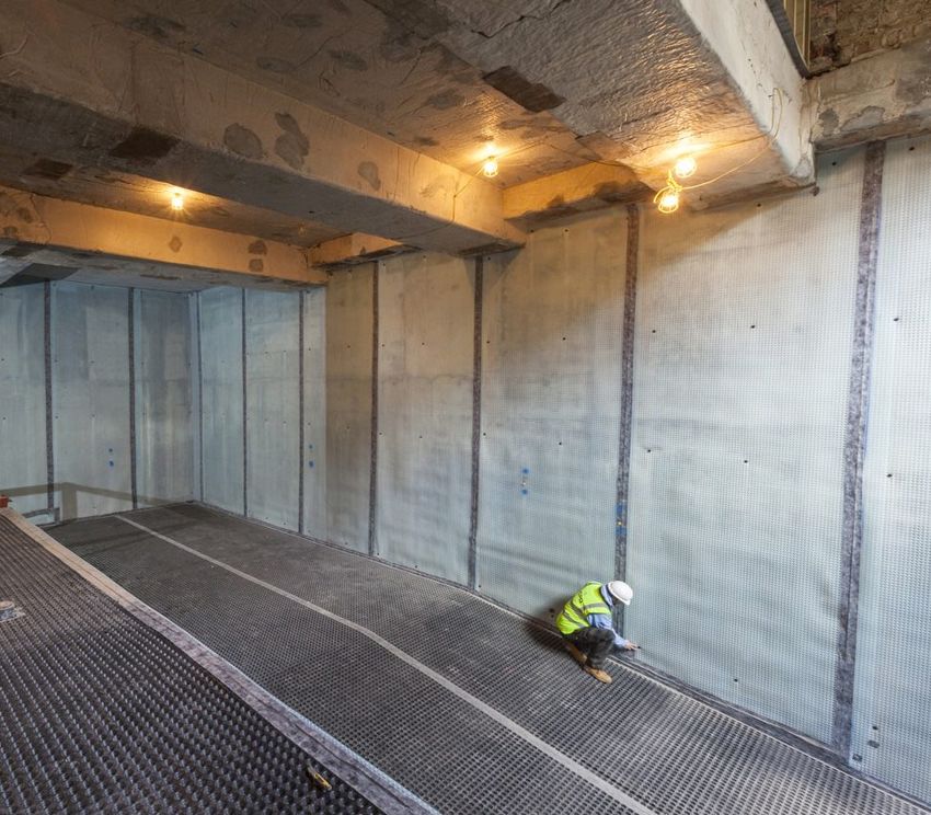
4. SHEET PILED WALL CONSTRUCTION
4.1. Cavity drainage membranes
Cavity drainage membranes are high-density dimpled polymer sheets, placed against the structure. The
dimples form permanent cavities between the structure and the internal shell. They are used internally
to drain and control water ingress, and are not designed to sustain water pressure as specific barrier
membranes.
Design considerations
• Installed following construction of the basement
• Installed during construction where an internal wall is built
• Defects may be rectified before completion
• Minimum preparation of substrate needed
• There is no hydrostatic pressure on the system: water entering the cavity is collected and drained/
pumped away
• They are of consistent thickness and quality
• Flexible and able to adapt to minor settlement and shrinkage within the substrate
• Simple internal applications can overcome complicated designs, e.g. piles and ground beams
• With high or variable water tables, blockages or failure of drains/pumps may lead to flooding
• Where recycled materials are to be used, their durability should be checked with the manufacturer
• Planned maintenance is a requirement
• Assessment of the permeability of the wall is required in order to determine requirements for water
collection and discharge
4.2. Floor Drainage Channels
A Floor Drainage Channel is a PVC drainage conduit (enclosed gutter) generally fitted around the
perimeter of the floor at the vulnerable joints and in conjunction with cavity drainage membranes. Water
entering the building through the walls is controlled behind the membrane and diverted down to the
drainage channel at the base of the wall. The water enters the drainage channel through pre-drilled
drainage holes to the rear of the channel and must then be diverted to a suitable drainage point, either
gravity or a sump and mechanical pump system. Mid-floor flangeless spine channels may be added,
to large or wide floors as additional drainage to link to the perimeter drainage. In a well-designed and
maintainable floor drainage system the means of access to clean out and maintain the channel must be
introduced at design stage. Ideally access points/jetting eyes should be installed at regular intervals to
ensure accessibility to the system.
134.3. Ancillary Products
4.3.1. Pump Systems.
Basement waterproofing sump pump systems are typically provided as a packaged unit comprising a purpose-
designed preformed sump liner or chamber with an integrated access cover over, which houses, as a minimum,
dual (duty standby) automatic float switch operated pumps. The pumps activate and remove water when it
reaches a set height within the liner. Pumps are always included at the lowest point within a structure, allowing
collection of penetrating water by gravity, and then lifting this up to a suitable external discharge point which must
be identified and appraised.
4.3.2. Battery Back-up Protection
Battery back-up pump systems are typically included to protect in the event of a power cut, with additional
mechanical pumps being added to provide further redundancy or additional capacity as necessary. Such
systems should include high level alarms to forewarn in the event of a problem, which may alert via local audible
alarm or, where required, remote telemetric phone call. Backup pumps and alarms should in MOST situations be
included, and always where there are consequences of failure. It should also be noted that:
• Type C systems require a maintenance schedule, as failure of mechanical pumps could result in flooding
• Where back up pumps are omitted the consequence and risk of a pump / power supply failure should be fully
understood and formally agreed by all parties
Refer to PCA Guidance document on Pumps and Drainage
4.4. Product Selection
Given the wide range of waterproofing materials and certifications available it is clear there are many options
when it comes to deciding upon a product or system for a given project. Historically and in most cases holding a
CE approved accreditation through appropriate independent testing bodies has been sufficient. However with the
changing requirements of Government, Europe and countries further afield, an assessment of the product for its
given application should be carried out. Areas which may be important to the application and that need assessing
could be:
• Product durability
• Expected life in service
• Resistance to aggressive environments (UV, contaminants, ground gases etc.)
• Waterproofing Ability
When selecting a product or system, it is also important to look at the supplier and/or manufacturer to confirm
what support they offer. This could include:
• Design advice
• Range and type of products
• Site support
• Post-application support
• Product training (designers and applicators)
Reference MUST always be made to Manufacturers Product Recommendations for the application of these products.
CE marked products
As from 1st July 2013, construction products placed on the market in the UK and covered by a harmonised standard
(hEN) or a European Technical Assessment (ETA) will have to be accompanied by a Declaration of Performance (DoP)
and will need to have the CE marking.
The scope of harmonised standards is likely to increase over time and as such it would not be practical to list them in
this document. It is however important that checks are made to ensure any products being used in works covered by
a hEN include appropriately CE marked products, as failure to do so can lead to financial penalties and further legal
complications further down the line (this applies to manufacturers, distributors, contractors and specifiers.
145. CAVITY DRAINAGE MEMBRANE APPLICATION, FITTING AND DETAILING
Preparation
When used in existing buildings, all plaster and any unsound render or screed is removed to expose
the substrate. Remove any nails or sharp objects and clean with a stiff brush to remove loose material,
laitance, salt residue, mould or adhesive. All timber and organic material MUST be removed. The surfaces
must be sterilised with an appropriate biocide. Uneven substrates should be made good and level with a
suitable repair material. They should be allowed to harden before the membrane is fixed. However the use
of cement based materials CAN introduce lime into the system which will necessitate treatment. Check
and remedy any unacceptable leaks in the concrete or masonry substrate using appropriate methods
before the system is installed. If there are large or structural cracks present, seek the advice of a structural
engineer.
Treatment of Free lime
Prior to installing the cavity drainage membrane on walls constructed of new concrete, the concrete
surface should be treated to reduce the risk of leaching of free-lime or mineral salts, this can be done with
a proprietary silicic acid compound crystallization slurry or epoxy coating.
Installation (General)
If the membrane is installed vertically it should always be used with the flanged edge positioned in front of
and overlapping the previously installed membrane width – studs to the wall. If the membrane is installed
horizontally, the position of the flange should be to the upper edge with the membrane installed to the
higher level first if the wall is greater than the membrane width. Joints must be formed in accordance with
the manufacturer’s instruction.
Fixings are made through the studs into holes drilled through the membrane. Fixing plugs with seals are
inserted into the holes and hammered flush with the membrane. Spacing and sealing of these fixings will
depend on the product being applied, the application, the nature of the substrate and the type of finish to
be achieved.
Soffits (Ceilings)
Cavity Drainage Membrane should not be applied to flat soffits. Soffits, to be covered, should always
have a fall (as for vaulted cellar constructions) so water does not lie against the membrane or a joint.
Refer to manufacturer or specialist waterproofing contractor for detailing. The membrane should be
adequately fixed, to avoid the possibility of water ponding on top of the membrane. The wall membrane
should be cut into the curve of the vault and fixed in accordance with the manufacturers’ instructions.
Walls
Installation of the membrane is commenced at the top of the construction. The membrane may require
initial fixing on the upper edge of a wall. Detailed instructions on the installation and jointing of wall
membranes should be provided by the manufacturer. The membrane is fixed in accordance with the
manufacturers’ instructions, using the appropriate fixing and sealing materials. Power points, cables, light
switches, pipes and any other services must be remounted in front of the membrane.
Dry Lining
Where timber battens are used ensure they are preservative treated, with cut ends adequately treated,
and fixed into the fixing plug’s internal fixing hole using the appropriate size screws.
An independent frame can be constructed in front of the system to accommodate wall finishes. This can
be constructed in timber or a proprietary metal track system can be used. Gypsum plasterboard to BS EN
520: 2004, or similar dry lining boards covered by a current Agrément Certificate, are fixed to the battens
or metal tracking with galvanized screws or nails, positioned a minimum of 12 mm from the edge of the
board. Care should be taken to ensure that penetration of the plasterboard screws or nails is less than
batten or tracking depth to avoid puncturing the membrane.
15When a plaster finish is required, the membrane on walls may be substituted by appropriate plastering/
rendering membrane, approved for use for below ground applications. This will be fixed, sealed, and
finished in accordance with the manufacturers’ instructions.
5.1. Applications on Floors
Preparation
Unsound or loose coatings such as screeds, laitance, salt residue, mould growth or adhesives must be
removed. If mould or fungi is present, the floor and walls should be treated with an appropriate biocide
(care should be taken to avoid contamination of watercourses when using biocides). Uneven substrates
should be dubbed out with a suitable mortar, to achieve a flat finish. This must be allowed to harden
before laying the membrane. Check and remedy, using appropriate methods, any unacceptable leaks in
the concrete or masonry substrate before the system is installed.
New concrete floors should be laid LEVEL.
The surface irregularities should be within tolerances of the drainage method to be used. A general
guidance is +/-5mm over any 10m direction is achievable, with the next 10m measured area being the
same tolerance if the previous 10m had no deviation and up to +10 if the previous measure was -5mm
and -10mm if the previous level was +10mm.
Carry out a flood test to check floor levels and to ensure that the drainage system works effectively.
Prior to installing the cavity drainage membrane on the floor, clean the horizontal substrate and remove
all dust and debris. The surface of new or repaired concrete should be treated to reduce the risk of
leaching of free-lime or mineral salts, e.g. this can be done with a proprietary silicic acid compound, epoxy
coating or crystalline slurry. If a board covering is to be laid directly on the membrane, the concrete base
must have a surface regularity with a maximum permissible departure appropriate to the cavity drainage
membrane that is to be used.
Drainage
Floors should have a drainage outlet point. Perimeter drainage channels used in conjunction with wall and
floor membranes ensure water will flow to the outlet or discharge point.
The outlet point will typically be a collection sump, which will then mechanically evacuate the water.
The need for drainage and the understanding of how drainage works is THE most important aspect of
Type C waterproofing system. A common failure with Type C systems is due to poor drainage design and/
or installation.
Refer to PCA Guidance document on Pumps and Drainage.
Installation
Before the floor membrane is laid all necessary perimeter drainage and access service points should
be installed. The membrane is rolled out, with the dimples/studs facing downwards, over the floor.
Consecutive membrane sections are laid so that the flange edges overlap. Where studded edges
overlap, this should be by no less than is required by the manufacturer. All joints are then sealed with the
appropriate materials in accordance with the manufacturers’ instructions. The membrane is cut around
pipes and services in the floor, and the gap sealed. Where appropriate, a patch of the membrane can
be laid over the surface, and sealed to the main membrane. Alternatively, this can be detailed using
pre-formed units. There should be no fixings through the horizontal floor membrane. Wall floor junctions
and corners should be given special consideration and should be formed and sealed and finished in
accordance with the manufacturers’ instructions.
16Floor Coverings
Before floor finishes are installed insulation boards can be laid over the membrane, (100% Closed Cell
insulation MUST be used – see section 6 on insulation). Suitable tongue-and-groove floor board panels can
be loose laid over the membrane to within 10 mm of the walls. The panels should be staggered and the joints
sealed. To avoid unevenness in the finished floor, it is advisable to install floor panels so that the joints do not
coincide with joints in the cavity drainage membrane. The membrane may be covered by concrete or screed
generally at thicknesses over 50 mm. Proprietary screeds may also be considered, which can generally be
laid at thicknesses less than 50mm. The use of these products with the membrane should be approved by
the membrane manufacturer. Care should be taken to ensure the membrane is not displaced when placing
the concrete or screed. Care should be taken with all screeds and bricklayers mortar that it does not enter
the channel. Self-levelling screeds are very fluid and pose a real risk of blocking cavities and channels if not
correctly detailed.All channels should be checked during and after screeding.
5.2. Accommodating Services
Services entering through a waterproofing system should be avoided where possible. Elements within
the construction such as service ducts or light wells can allow for services to be brought in from above,
therefore avoiding any compromising of the system.
Where services penetrating the system are unavoidable the design and detailing to seal such elements
should ensure that they are watertight and durable and suitably situated to allow for such works to be
carried out (having them too close together can be problematic for detailing). In all cases details that
penetrate a waterproofing system should be detailed and installed in accordance with the relevant
manufacturer’s guidelines.
5.3. Continuity with other systems and trades
Careful detailing of connections to above ground elements (e.g. dpm’s, dpc’s) is important to ensure
consistency for the overall structures performance. Where possible have a complete system from one
source. Details can then be more easily confirmed as compatible.
As important as maintaining consistency between systems, communication and an appreciation of other
trades are vital for a successful installation and end result. Regular meetings and communication sessions
should be held to ensure that all parties involved at any one stage are aware of current or future works to
ensure each can take place, be installed and ultimately function as intended.
6. INSULATION IN BASEMENTS
Insulation as a void former
Only high performance 100% Closed Cell insulation materials are recommended because of negligible
moisture absorption and high compression resistance.
7. ISSUE OF ‘FREE LIME’ IN CAVITY DRAINAGE SYSTEMS
The use of cavity drain systems, as a method of waterproofing, has become the commonest form of
waterproofing system used in retrofit basements and increasingly is being fitted in new build basements.
In accordance with the Code of Practice BS8102: 2009, they need to be maintained. This has been helped
significantly with the introduction of perimeter drainage channels and inspection ports, so as to make the
drainage aspects maintainable and help to prevent blockages caused by the existence of free lime for example.
In most new construction and retrofit basements (and also in refurbishment projects where the floor has been
replaced), there is a high risk of free lime and /or mineral salts leaching from the concrete walls and floors. In
retrofit this is particularly prevalent where “dry pack” is used at the top of the underpinning.
As free lime leaches from the new construction by groundwater ingress it deposits itself within the drainage
cavity, (behind and underneath membranes) and particularly within the sump chamber and around the sump
pumps. Thus potentially causes pump failure and therefore failure of the system.
Maintenance of cavity drain systems and discharge points is vitally important to the long term success of the
system. A schedule of maintenance should be incorporated in the design of the waterproofing system. The first
17service should be considered within the first three to six months. In some circumstances it may be necessary to
amend the time and scope of the service visits. Any changes to the schedule of planned maintenance must be
agreed with the client so that the service schedule is amended accordingly.
The impact of free lime within the system will greatly increase the frequency of maintenance over the first
3 – 5 years, but especially within the first six months, reducing the interval to weeks in some instances, thus
increasing both the costs of maintaining the system and also putting the system under undue risk.
In order to minimise the risk of free lime impacting on the system, an “anti-lime” coating should be applied to
the new concrete IN ALL CASES.
Long term benefits include significantly reducing the risks to the system and saving maintenance costs.
For further detail refer to PCA documents on Free Lime and Dry Pack in Basements
The British Standard BS8102: 2009 says that the water management system should be “serviceable and
maintainable”, regrettably this is very often forgotten and rarely serviced, for a variety of reasons:
• No knowledge of where the service points are.
• The internal dry lined walls are built out too far forward and obscure access to the service point(s).
• No water available to flush out the system.
• Concerns about damaging finishing’s (water damage).
Maintenance is essential for all Type C systems, even those without mechanical pumps, and steps should be
taken to avoid the scenarios highlighted above.
The client should be given a site plan on completion, indicating the exact location of the service points and
be made aware of the importance of the pump service and channel inspection. This should be a condition of
guarantee.
Anti-Lime Solutions: preparatory Anti Lime Solutions are designed to remove carbonate deposits in
groundwater bores, wells and pumps and are therefore particularly well suited for the removal of lime scale and
other build up within cavity drain systems, sumps and pumps.
Benefits:
• Clears lime scale build up from cavity drain systems
• Fully biodegradable
• Ready to use
• Discharge into foul drains is acceptable
8. DEFECTS, REPAIRS AND MAINTENANCE
In order to ensure the long term integrity and effectiveness of the waterproofing system the property and
the waterproofing system must be properly maintained.Waterproofing systems should be able to cope with
water arising from leaking drains and domestic water pipes however, it is essential that all buildings are
maintained to prevent water ingress and waterproofing systems are no exception. If the property and its
drainage systems are not maintained then the underground structure may be subject to water ingress from
sources that were not considered during the design of the waterproofing system.
It is important to ensure the client is aware of their responsibility to maintain the property. Special attention
should be paid to:-
• Drainage channels
• Sumps and Pumps
• Drains and soakaways
• Rainwater goods,
• Gullies and culverts
18• Excavated external window lights and stairwells
• Air bricks and ventilation systems
Cavity Drainage Systems
As cavity drainage systems rely on free drainage usually in association with sumps, perimeter drains and
mechanical pumping devices it is essential that these elements are regularly maintained to ensure their
long term effectiveness.
Immediately after the installation of a drainage system, the drainage channels and sumps MUST be cleared
out and tested. Pumping devices must be checked, tested and properly commissioned. The drainage
systems should then be inspected and serviced at regular intervals. It is recommended that service
intervals should be no longer than annual. It is vitally important that the first service is within 3 months of
the installation as it is within this period the system is most subject to Limescale. It is also possible that
debris and site waste can find its way into the sump chamber during construction. This MUST be removed
and the chamber cleaned at this first service.
In circumstances where pumps are running for long periods of time, or where the system is subject to
silting or the depositing of free lime, service intervals may be far shorter. The design specialist has the
responsibility for any guarantee issued on the system - that the waterproofing system is fit for purpose.
They MUST instigate a MAINTENANCE REGIME for setting service intervals. Commonly this involves a
service contract with a pump service engineer as most contractors do not service their own systems.
The servicing requirements for the waterproofing system should be clearly set out in the specification and/
or contract and/or guarantee, supplied by the designer to the client. The client must be informed that any
failure to adhere to the maintenance schedule may result in a failure of the waterproofing system.
It must be made clear to the client that any system failure that results from a deviation from a planned
maintenance program will not be the responsibility of the installer and will not be covered by any guarantee
that has been issued.
Condensation
Condensation is dampness generated from within a structure and will not be eliminated by the application
of a structural waterproofing system. It is important to consider the likelihood and implications of
condensation when the waterproof system is being designed. Waterproofing systems that conform to
Grade 3 (BS8102: 2009) should usually include reference to heating and/or ventilation.
Condensation can usually be controlled by adequate air control such as increasing ventilation,
dehumidifiers or a central air conditioning system. Increasing the internal temperature without improving
ventilation can make matters worse. Interstitial condensation can be cured in the same way.
Minor condensation problems can often be cured by adjusting the heating patterns. Leaving the heating
on permanently at a lower temperature will sometimes be sufficient. The most effective means of removing
condensation risk is to reduce the volume of vapour held within the air and by doing so, the relative
humidity. A humidistat controlled fan or dehumidifier should be installed to do this.
Further information on condensation can be found in the PCA Advisory Leaflet on Condensation.
System Failures
General water penetration and breaks in the system will need to be dealt with in accordance with the
manufacturers recommendations.
9. SERVICE AND MAINTENANCE OF CAVITY DRAINAGE
WATERPROOFING SYSTEMS
The need to service and maintain the drainage elements of a Type C Waterproofing system is paramount to
its long term success. This is highlighted in BS8102, the PCA Code of Practice for Remedial Waterproofing of
Structures below Ground and by the distributors of products and equipment used to create waterproof basements.
19You can also read