Beyond Automotive Measurement, Calibration & Diagnostics Portfolio Overview - Accurate Technologies
←
→
Page content transcription
If your browser does not render page correctly, please read the page content below
Beyond
               Automotive
              		Measurement, Calibration
              		 & Diagnostics Portfolio Overview

DATA           ECU           ECU RAPID     ECU          CAN BUS      NETWORK     TEST CELL     ENHANCED
ACQUISITION
  AC           CALIBRATION   PROTOTYPING   INTERFACES   INTERFACES   SOLUTIONS   MEASUREMENT   DIAGNOSTICS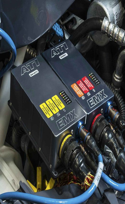
Over 25 years
        connecting products
        and people through
        innovation

          Accurate Technologies Company Timeline

       1994       1995          1997        1998                         2002              2005                        2009                 2014                        2018        2020
       Injector   SmartTach     EDAQ        VISION 1.0                   Apollo Pro        CANLab 1.0                  EMX                  CANary                      CANary FD   AE-100
       / Coil     Speed         Data        & VISION HUB                 Data              Bus Analysis                Data                 Interface                   Interface   Automotive
       Driver     Measurement   Acquisition Calibration                  Analysis                                      Acquisition          Module                      Module      Ethernet
       modules                              Software                     Software          CANverter                                                                                Adapter
                                ROM2CAN
                                Emulator

1992                                             2000             2001          2003              2006        2007                   2013           2015         2017               2020 Cont.
COMPANY FOUNDED                                  UNITED KINGDOM   GERMANY       SWEDEN            JAPAN       FRANCE                 INDIA          CHINA        25 Years           NS-1
US Office                                        Office           Office        Office            Office      Office                 Office         Office       Anniversary        Network
Opened                                           Opened           Opened        Opened            Opened      Opened                 Opened         Opened       Move to new        Switch
                                                                                                                                                                 expanded
IGTM 1000                                        M5               No-Hooks      M6                A7                                 A8             DLX          Headquarters       A9
Timing                                           Memory           Rapid         Memory            Serial                             Serial         Datalogger                      Serial
Measurement                                      Emulator         Prototyping   Emulator          Interface                          Interface                                      Interface

                                                           MEASURE • CALIBRATE • DEVELOP • OPTIMIZE • SUCCEED
More than 25 years
of advanced technology,
successful collaborations
and valued partnerships
ATI - Your Global Measurement,
Calibration and Diagnostics Partner
With a quarter of a century of experience in developing
cutting-edge software and hardware solutions for the
measurement, calibration and diagnostics (MCD) sector,
Accurate Technologies Inc.’s (ATI’s) extensive product
portfolio is used globally by major OEMs and Tier One clients
across a wide variety of automotive powertrain formats.
ATI also manages numerous clients in the defense, marine
and aerospace sectors, where the company’s innovative                                   Opened in 2017
approach and high levels of customer service and support                  ATI’s new global headquarters
are vital factors in the firm’s success story.                             in Novi, Michigan USA is five
                                                                                    times larger than its
                                                                                        previous facility
Since the company was formed in 1992, its central objective
has been the same - to create advanced, user-friendly products
that enhance both productivity and efficiency for powertrain
and vehicle manufacturers, testers, calibrators and suppliers.
Headquartered in a purpose-built, state-of-the-art 120,000 sq ft
development and manufacturing facility in Novi, Michigan USA,
customer support is provided globally by ATI subsidiary offices
in China, France, Germany, India, Japan, Sweden,
and the United Kingdom.

Combining unrivalled market knowledge and a complete
understanding of what really matters to you, the customer,
ATI is dedicated to delivering innovative value added MCD
solutions, always with an emphasis on the ease of use.

                     MEASURE • CALIBRATE • DEVELOP • OPTIMIZE • SUCCEED                            •1
                                                                                                    9•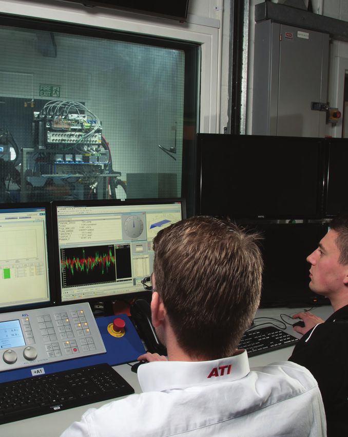
Over 25 years
as reliable
hands-on
service partners

•2•       MEASURE • CALIBRATE • DEVELOP • OPTIMIZE • SUCCEED
ATI is a product-based
company, but its business
philosophy is that of a
Service Organization
Rather than selling a static product to everyone,
ATI develops MCD software and hardware solutions that
are designed from the outset to adapt to customer processes
and requirements. ATI’s service-led approach is adopted by
all aspects of the company’s activity; including new product
development, worldwide employee recruitment to most
importantly, its renowned customer service.

ATI - A distinctive business philosophy for
an independent Corporation
• ATI functions as a product based company,
  but with a service organization mentality                                    Partnerships are central
                                                                           to ATI’s business philosophy
• Being independent, ATI supports all ECU suppliers
  equally without conflicts of interest                                   Every customer - irrespective of
                                                                            size - is a potential long-term
• ATI is run for engineers, by engineers, with swift reactions
                                                                             collaboration as they benefit
  to users’ ongoing requirement changes                                      from ATI’s ongoing support,
                                                                                     training and software
ATI Product Quality - Products exclusively manufactured                                   product updates
at its US facility
• Comprehensive manufacturing processes using
  state-of-the-art equipment
• Manufacturing processes implement a continuous
  improvement model
• Partnered with industry leading qualified suppliers
• Total ownership and safeguards of both ATI and customer
  intellectual property
• Single location housing both engineering and manufacturing
  facilities offers rapid issue resolutions and customer
  request integration

                     MEASURE • CALIBRATE • DEVELOP • OPTIMIZE • SUCCEED                              •3
                                                                                                      9•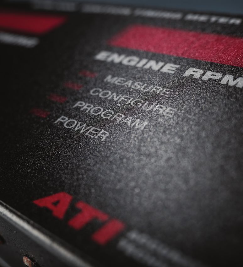
ATI’s Product Portfolio
An Integrated MCD Toolchain
      ATI’s range embraces hardware,
      software and associated 3rd party
      products across an integrated                                    ECU
      toolchain designed to maximize                                Interfaces
      productivity, efficiency and
      development capabilities for
      ECU module and / or powertrain                      DAQ & I/O
      development.                                        Hardware

                                                Software

                                       Test Cell

•4•                   MEASURE • CALIBRATE • DEVELOP • OPTIMIZE • SUCCEED
HV Measurement Modules

Serial Interfaces                          Data Acquisition Devices

CAN Interfaces                             Dataloggers

Kvaser CAN bus                             I/O Modules
Interfaces & Loggers

                                           ECU Calibration,
                                           Data Acquisition
                                           & Diagnostics
Ignition
Timing Meter
                                           Data Analysis

SmartTach
Module                                     ECU Rapid Prototyping

PICOTURN
Turbocharger Speed                         CANLab Multi-bus
Measurement                                Network Analysis

MEASURE • CALIBRATE • DEVELOP • OPTIMIZE • SUCCEED                 •5
                                                                    9•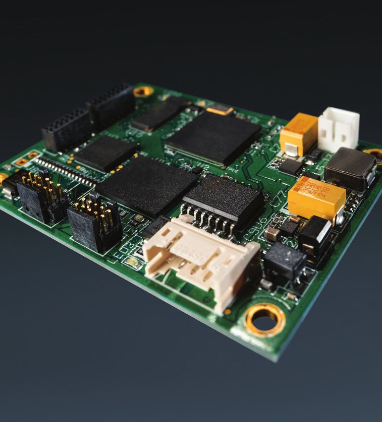
Software Portfolio

•6•     MEASURE • CALIBRATE • DEVELOP • OPTIMIZE • SUCCEED
VISION Software Suite

VISION
Software Suite

                                                                        POWERFUL
                                                                                           API                       INTUITIVE   MODEL BASED
                                                                                                         REMOTE
                                                                                                       DASHBOARD
                                                                        POST PROCESSING
                                                                           FEATURES
                                                                                                      CONNECTIVITY     design    CALIBRATION
                                                                                          AVAILABLE

VISION is an innovative, user-friendly, powerful, comprehensive software                          Key VISION Software
solution that is available in numerous versions incrementing in toolkit                           features include:
functionality. VISION offers a wide range of capabilities ranging from basic                      • ECU Flashing, Calibration
data acquisition to post-analysis, ECU calibration and ultimately the rapid                         and Rapid Prototyping packages
prototyping of module functionality using patented No-Hooks technology.                           • Data Acquisition and Data Analysis
                                                                                                    packages
VISION offers fully integrated calibration and data acquisition capabilities
                                                                                                  • Intuitive GUI design
including signal collation from ECUs and external sources, plus measurement
                                                                                                  • Powerful API and post processing
and the real-time calibration and modification of closed-loop control systems.
                                                                                                    features
In addition VISION time aligns data and facilitates the analysis of information,
                                                                                                  • Model based calibration available
manages calibration changes and enables flashing of the ECU.

VISION now includes a ‘Remote Dashboard’ feature which enables users
to remotely view and monitor VISION on secondary displays including
smartphones and tablets. Powerful and versatile, Remote Dashboard is also
capable of automating and executing some common functions of the
VISION software host environment.

                                                   3D Calibration Tables and
                                                   dial gauges are key graphical
                                                   representations of calibration
                                                   data and measurements
                                                   available within VISION.

                       MEASURE • CALIBRATE • DEVELOP • OPTIMIZE • SUCCEED                                                            •7
                                                                                                                                      9•
VISION Software Suite

VISIONview/measure
Customizable, Easy-to-use

                                                                                                  SUPPORTS

                                                                                                  POPULAR
                                                                                      IMPORT        FILE
                                                                                      EXPORT      FORMATS     DAQ HW
                                                                                                              READY

VISIONview is a customizable, yet easy to use tool for post-data analysis             Key VISIONview
of recorded data. Essential elements of any data analysis tool include the ability    features include:
to manipulate and view data in a way that highlights results, differences,            • Create multiple views
and specific events. ATI’s VISIONview enables comparisons, overlaying,                  of the same data set
and detection of data or events while easily handling data sets with                  • Create calculations based
1000+ channel counts.                                                                   on recorded data
VISIONview’s powerful post-data analysis features include the use of XY               • Create templates for
plots to graph one variable against another, and file overlays to view data from        quick formatting of data
multiple files on the same graph. Use VISIONview’s Calculated Channels to             • Overlay recordings
enhance information, layout templates to expedite set up of similar tasks or tests,     for comparison
and the convenient Recorder Catalog for recording management. Import/export           • Export segments
in popular file formats (MATLAB, MDF, HDF and ASCII) including the ability              of recorded data
to export a reduced data set for focused analysis.
                                                                                      Key VISIONmeasure
VISIONmeasure adds the ability to view data during collection from ATI’s              features include:
EMX DAQ devices. Collection and analysis are supplemented with a wide
                                                                                      • Simultaneous view
range of customizable display objects that enable viewing real-time data as
                                                                                        of multiple graphs
it is acquired by ATI’s range of data acquisition devices.
                                                                                      • Import/Export capability
                                                                                        with other file formats
Select from a collection of customizable display objects such as stripchart
recorders, oscilloscopes, LEDs, gauges and thermometers. Change colors,
fonts, sizes and other appearance aspects of each individual object.

•8•                              MEASURE • CALIBRATE • DEVELOP • OPTIMIZE • SUCCEED
VISION Software Suite
VISIONdaq/daq+
Advanced Monitoring & Analysis
THIRD TIME
ALIGNED
PARTY ECU ASAM
DAQ HW INTERFACE CCP/XCP
SUPPORT DATA COMPATIBLE
VISIONdaq features an enhanced set of capabilities compared to Key VISIONdaq features include:
VISIONmeasure, including advanced recording, monitoring and analysis • Support for industry standard
functionality for a broad range of industry standard third party CAN data third party DAQ modules
acquisition devices.
Key VISIONdaq+ features include:
VISIONdaq+ adds additional support for acquiring time aligned data
from a wide variety of ECU interfaces using commonly found ASAM CCP • Support for time aligned
or XCP protocols to ensure the widest possible compatibility with ECU interface data
legacy hardware. • ASAM CCP and XCP
compatibility
Acquire, view and analyze
data, exploit advanced
features in conjunction with
ATI or legacy DAQ hardware.
MEASURE • CALIBRATE • DEVELOP • OPTIMIZE • SUCCEED •9•VISION Software Suite
Data Analyzer
Industry Standard Data Analysis
INTUITIVE
DESIGN MDF4
COMPATIBLE
IMPORT
EXPORT
VISION Data Analyzer (VDA) 3.0 and up is a 64-bit application specifically Key VDA Software features include:
designed for viewing industry standard MDF4 file formats of any size and from • 64-bit application allowing it
both ATI and 3rd party software. VISION Calibration and Data Acquisition access to more memory and
Software is capable of exporting and recording directly into MDF4 format. large data files that would be
Exporting .rec files into MDF4 files will allow viewing of recorded data in VDA impossible to open in VISION
that would be too large for viewing within VISION. • Uses industry standard ASAM
VDA Display presents each recorder file as an independent layout tab containing MDF 4.1 as its standard file format
pages with graphs and side windows. Layout tabs are designed to be detached • Only loads the channels that are
(float mode) outside the applications framework or docked to various locations needed from the file to optimize
within the framework workspace. Page layouts can contain up to sixteen performance
independently configured graphs. Configurations consists of resizing, adding, • Allows the user to save overlay
removing, renaming, configuring graph color themes, and adding/removing configurations into a Vision Data
additional Y-axes. Analyzer project file (VDAP)
• VDAP projects can be packaged
into a zip file
VDA has popup tool tips such
as interactive floating cursor
window that displays the current
cursor positions and the time
delta between the cursors
• 10 • MEASURE • CALIBRATE • DEVELOP • OPTIMIZE • SUCCEEDVISION Software Suite
Enhanced Diagnostics
Advanced Vehicle
On-board
Diagnostics
SOFTWARE COMPREHENSIVE DATA ITEM
DEVELOPMENT INTEGRATION ENHANCED
KIT GUIDES DIAGNOSTICS
VISION Diagnostics is the combination of the CAN OBDII Toolkit and the Key EDT Software features include:
Enhanced Diagnostics Toolkit (EDT). This provides VISION with • Full integration with VISION’s Data
integrated support for legislated OBD functionality and advanced features Item Manager, screen controls,
available in World-Wide Harmonized On-Board Diagnostics (WWH-OBD). and recorders to optimize work
flow.
EDT extends VISION’s diagnostic capabilities to include ISO-14229 diagnostic • Simplify data collection
services. These services can be accessed using the feature rich API. In addition and analysis by combining
to reading and clearing codes, EDT allows users to gain access to extended Measurement, Calibration and
trouble code descriptions and help information (when available), plus access to Diagnostics data onto a single
hundreds of additional parameters that can be viewed in real-time. recording.
• Auto-detect connected ECUs for
quick discovery and connectivity.
Manual overrides for custom
applications.
Comprehensive API
documentation, quick-start
guide, and SDK with example
source code
MEASURE • CALIBRATE • DEVELOP • OPTIMIZE • SUCCEED • •11
9•Rapid Prototyping No-Hooks Software
No-Hooks
ECU Variable Bypass
FAST
BYPASS
&
VERSATILE COST
PATENTED ECU
INSTRUCTION
EFFECTIVE
CODE
ATI offers an innovative, patented software-centric method for rapid Key No-Hooks features include:
prototyping production ECUs with its sector leading No-Hooks technology. • Bypass ECU instruction code
Functioning as an extension of VISION Calibration and Data Acquisition • No source code needed
Software, the primary benefit of No-Hooks is that it allows users to internally • Fast and cost effective
bypass Read-Only control variables in the ECU’s RAM with calibratable • Fault simulation
parameters.
As such, ATI’s No-Hooks enables users to explore a wide variety of advanced
rapid prototyping applications including system validation and fault injection,
all without requiring costly external hardware-in-the-loop (HIL) systems.
• Use only the standard files needed for calibration;
the original ECU source code is not required
• Perform rapid prototyping; then calibrate on your prototype and
acquire data within the same tool
• Calibrate the base strategy and the bypass model simultaneously
No-Hooks is fully integrated within ATI’s VISION Calibration and
Data Acquisition Software.
• 12 • MEASURE • CALIBRATE • DEVELOP • OPTIMIZE • SUCCEEDRapid Prototyping No-Hooks Software
Advanced No-Hooks
Dynamic Hooks Without
MATLAB/Simulink ®
FAST
BYPASS SCRIPTING
&
VERSATILE COST
PATENTED ECU
INSTRUCTION
EFFECTIVE
FUNCTIONALITY
AS STANDARD
CODE
Advanced No-Hooks is based on ATI’s patented No-Hooks technology, Key Advanced No-Hooks
extending it to allow ECU functionality to be modified by user defined features include:
functions, without access to the original ECU source code or the need for • User defines a function in C-like
other applications such as MATLAB/Simulink®. syntax for the dynamic hook
value using VISION data items,
Advanced No-Hooks shortens the development cycle to bring products to
constants, and Advanced No-
market faster. The prototype runs on production intent ECU which corresponds
Hooks variables
in every way to improving the success of the final product. The Advanced No-
• No-Hooks DLL creates
Hooks bypass runs in-line with the rest of the original code on the target ECU.
There is no need for data transfer protocols or the resulting delays for running the relocation and trigger code
bypass on external devices, which translates into virtually no latency. • Function Library and function
editing with syntax highlighting.
• Requires only No-Hooks DLL for
target CPU
Each hooked item can have its own
function. Hooked item functions can be
selectively enabled/disabled to control the
bypass operation as an Advanced or base
No-Hooks bypass.
MEASURE • CALIBRATE • DEVELOP • OPTIMIZE • SUCCEED • •13
9•Rapid Prototyping No-Hooks Software
OnTarget
Advanced ECU RP
FAST
Simulink BYPASS &
VERSATILE COST
Models ECU
INSTRUCTION
EFFECTIVE
SUPPORTED CODE
OnTarget enables the expanded capability to integrate custom model Key OnTarget features include:
based control algorithms into existing ECU code. • Original source code is not required
• Provides additional Simulink blocks
In the No-Hooks tradition, there is no need for access to or modification of the ECU to stitch models into existing code
source code; all that is required are the ECU executable and description files. • Integrates seamlessly with VISION
• All the features of No-Hooks Rapid Prototyping
• Bypass variables with outputs from a Simulink® model, allowing the addition
of an entirely new control algorithm to be added to the existing ECU code
without modifying the original ECU source code
• Free ATI GNU compiler is available for a variety of micro-controllers
• Supports most microprocessors commonly used in ECUs
• Cost effective for design and validation of new algorithms
• OnTarget is ideal for the prototyping and testing of new closed-loop functions
and Function A/Function B comparison testing
• Harnesses the modeling abilities of Simulink combined with the calibration
support of VISION
• 14 • MEASURE • CALIBRATE • DEVELOP • OPTIMIZE • SUCCEEDRapid Prototyping Model-in-the-loop Software
Model Based Calibration
Implementation of
Model-in-the-
loop
INTUITIVE Simulink
DESIGN VERSATILE
Models
MODEL
IN-THE-LOOP
SUPPORTED
The VISION Model Based Calibration toolkit (VISION MBC) is the Key MBC features include:
implementation of a Model-in-the-loop (MIL) system. The MathWorks’ tools, • Integrates VISION with existing
MATLAB® and Simulink®, provide the modeling environment and VISION models by linking VISION and
MBC provides the ‘in-the-loop’ capability, integrating VISION with the model the model running within the
as it runs natively within the Simulink® environment. Simulink® environment on the
VISION computer.
The MBC System interrogates the model to discover the set of supported • Once the model is integrated,
signals and parameters within the model. These signals and parameters are then VISION will use the same
incorporated into a VISION Strategy file (*.vst) which in turn is associated with the interface used by all other
MBC Device within VISION. Once so incorporated, the signals and parameters devices within VISION. The
discovered within the model are exposed to VISION as standard data items distinction between this virtual
that may be used in data lists, recorders, table editors, etc. The MBC device in device and all other physical
VISION must also control (load, start pause, step, and stop) the model as it runs in devices is transparent to
simulation (which may also be done directly in Simulink). VISION.
• Powerful display of signals and
calibration parameters, including
configurable strip charts,
recorders, lookups, dials and
gauges.
• Viewing of the model in VISION
along with dynamic data
overlays using the optional
VISION Browser for Simulink®
Models Toolkit.
MEASURE • CALIBRATE • DEVELOP • OPTIMIZE • SUCCEED • •15
9•CANLab CAN Analysis Software
CANLab
Multi-bus Network Analysis
SUPPORTS
LOG
INDUSTRY SCRIPTING
CAN FD
READY
SEND
REPLAY LEADING
INTERFACES
INTUITIVE
design
FUNCTIONALITY
AS STANDARD
CAN DATA
CANLab is a multi-bus network analysis tool that provides a complete Key CANLab features include:
solution for key industry standard network protocols such as Controller Area • Intuitive GUI design
Network (CAN) including SAEJ1939 and Local Interconnect Network (LIN). • Log, send and replay CAN
and CAN FD data
Support of popular databases and hardware with advanced post analysis • Supports industry leading
is always included. CANLab can be used to view network activity, interfaces
send and receive signals or messages, record and replay data, manipulate • CCP/XCP/KWP Protocol
and analyze data, and check statistics, all in real-time: Decoders
• Accommodates most CAN hardware interfaces
• Offers analysis and scripting at no extra cost
• Provides a sophisticated strip chart recorder and replay
• No need to stop for changes - start or stop recording on the fly
• Connect or disconnect hardware without stopping the software
CANLab features dials and
gauges for viewing signals that
significantly improve the data
analysis process. Recorded or
‘live’ signals and statistics can be
graphed and analyzed simultane-
ously.
• 16 • MEASURE • CALIBRATE • DEVELOP • OPTIMIZE • SUCCEEDDAQ Hardware Portfolio
MEASURE • CALIBRATE • DEVELOP • OPTIMIZE • SUCCEED • •17
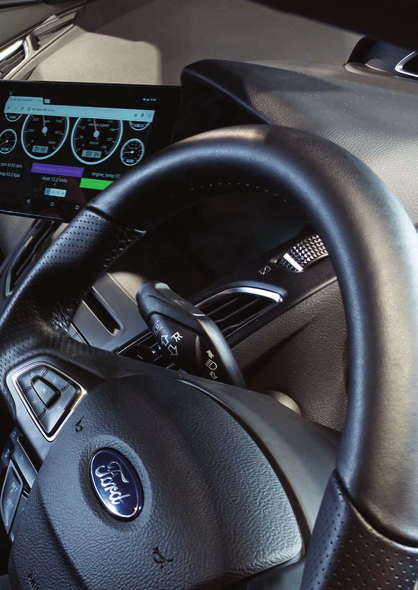
9•EMX 2.0
Data Acquisition
Redefined
ETHERNET
CONNECTIVITY
The EMX 2.0 Data Acquisition product line is based on a modular chassis
design offering combinations of internal measurement module types to support
different applications. This provides cost-effective flexibility and efficiency for
various channel count needs. Multiple input types are supported within a single
EMX device, avoiding the higher cost, extra space, and extra cables needed for a
cluster of chained-together devices having only one type of measurement each.
Measurement inputs typically provide several software configurable options per channel
including advanced DSP filtering algorithms with selectable filter response characteristics
and stop band frequencies to ensure repeatable and accurate measurements of the
performance level that typically requires laboratory style equipment. Each channel also
allows independent selection of its output data rate.
Flexible communication options are available including CAN/CAN-FD and Ethernet. When
used with ATI software products like VISION, the EMX operates as a plug and play device
and benefits from enhanced features including dynamic acquisition rates and automatic
filter compensation. Quickly integrate high quality EMX data with any generic CAN/CAN-
FD based acquisition system using the EMX’s open Message Based Protocol (MBP).
MBP allows for the highly flexible freeform configuration of free running CAN message
formats and rates – a feature not commonly found in traditional CAN based DAQ
hardware.
• 18 • MEASURE • CALIBRATE • DEVELOP • OPTIMIZE • SUCCEEDEMX Data Acquisition Modules
EMX modules feature a hermetically
sealed design, internal damping,
hard-anodized billet aluminum IP67
rated enclosures and aerospace-grade
Deutsch connectors.
Key EMX DAQ module features include:
• Analog, thermocouple, and cost-effective mixed I/O types available
• Accuracy and precision typical of larger, more costly laboratory style equipment
• Advanced anti-aliasing and DSP filters with selectable filter characteristic/cutoff
• Multiple thermocouple types: B, E, J, K, N, R, S, T, selectable per channel
• Advanced quick response thermocouple cold-junction compensation
• Competitive cost-per channel especially for high channel count applications
o Flexible communication interface options CAN and CAN-FD for easy daisy-chaining
o Ethernet with hardware IEEE-1588 PTP time sync for maximum performance
o Generic message-based open protocol available
• Aerospace grade connectors and hard anodized billet aluminum enclosure design
• IP67 rated for installation in vehicles or other rugged environments
• Wide operating temperature range for hot and cold weather testing
• Variety of I/O breakout cable and breakout box options available
The EMX design is based
on a modular chassis,
available in thermo, analog or
as a combination of channels,
in a variety of size formats.
MEASURE • CALIBRATE • DEVELOP • OPTIMIZE • SUCCEED • 19 •DLX Datalogger
DLX
Compact
Datalogger
SUPPORTS
CAN
IP65 MDF4 ROBUST
ANALOG & AND
K-LINE
THERMOCOUPLE
MODULES DESIGN
CHANNELS RATED COMPATIBLE
The DLX Datalogger offers a unique combination of functions, Key DLX Datalogger
providing the features of a CAN interface, data acquisition module, features include:
and datalogger all in one compact package. Communication channels • Four digital input/output channels
include CAN and K-line that interface to ECUs or communicate • Four +/-5 V differential analog inputs
with ATI data acquisition hardware. • Four 0 to 20 V single-ended
analog inputs
The DLX brings a robust and cost effective datalogger and calibration interface • Four K-type thermocouple
to small engine development, including eight analog channels, one sensor power input channels
output, four thermocouple channels and four digital input/output channels. • Two high speed CAN 2.0B channels
This combination ensures that ECU and instrumentation data are properly • One ISO 9141 compliant
correlated for easy analysis. The small form factor and IP65 rating make K-Line channel
the DLX ideal for space constrained applications.
ATI’s all-new VISION Data Analyzer enables users to view DLX Datalogger
data stored in ASAM MDF4 version 4.1 file format without requiring an additional
software utility to interpret MDF4 files - a first for data loggers in this segment.
Data is stored on the
DLX in ASAM MDF V4 files
that can be easily accessed
by using the USB port or
removing the SDHC card.
• 20 • MEASURE • CALIBRATE • DEVELOP • OPTIMIZE • SUCCEEDKlaric High-Voltage DAQ Modules
Klaric
High Voltage
Modules
IP65 ETHERNET
CONNECTIVI TY HIGH
Klaric and ATI partnered to leverage the synergies between ATI’s Key Klaric High Voltage Module
measurement and calibration competencies and Klaric’s competitive features include:
advantage in the high voltage sector. • Galvanic isolation up to 1500V DC
• Sample rate up to 8 kHz
The Klaric range of high-voltage modules and EV Charge Monitors is the • CAN data output
perfect, high-quality hardware compliment to ATI’s VISION Calibration and Data • XCP-on-Ethernet data output
Acquisition software packages, which have been successfully used by global • Dynamic sampling rate minimises
OEMs and Tier Ones in hybrid and EV platforms. data volume
• Automatic measurement range
These data acquisition systems are optimized for testing new electric and hybrid selection reduces implementation
vehicles making tasks easier, safer and faster. Klaric’s precision measurement setup time
modules have Ethernet, CAN and USB interfaces for monitoring data output, • Automatic probe identification
setting range selection, and making automated measurements.
reduces setup time
Use a standard Klaric
breakout box solution or
a DIY breakout box which
provides glands for HV
cable harness integration.
MEASURE • CALIBRATE • DEVELOP • OPTIMIZE • SUCCEED • 21 •Serial ECU Interface Product Portfolio • 22 • MEASURE • CALIBRATE • DEVELOP • OPTIMIZE • SUCCEED
A8 Serial ECU Interface

A8
High-Speed
ECU Serial
Interface

             HIGH                    ETHERNET          USB
                       DYNAMIC
  ACQUIRE
 CALIBRATE
  & FLASH
   IN-ONE
             SPEED
             ECU DAQ
                        DATA RATES   CONNECTIVITY   CONNECTIVITY

The A8 is ATI’s next generation of ECU serial interfaces, providing easy            Key A8 Serial ECU Interface
connectivity between a PC USB or Ethernet port and an Electronic Control            features include:
Unit (ECU). Connecting via the microprocessor’s debugger interface,                 •   Fully integrated ECU interface
the A8 enables data acquisition, calibration, and flashing functionality to the     •   Acquire, calibrate and flash all-in-one
ECU’s microprocessor memory regions. Connecting through the debugger                •   High speed ECU data acquisition
interface provides the capability of acquiring data and flashing the ECU            •   Dynamic data rates
at a significantly higher rate than via the CAN bus.                                •   Plug and play USB or Ethernet
                                                                                        connectivity
The A8 allows modification of the ECU memory without interrupting the
ECU processor. Keeping up with technology, the A8 supports the latest
microprocessors’ debug interfaces including JTAG, OCDS, Nexus, and DAP2.
Additional processors can be supported based on customer requests.
Built for automotive environments, the A8 is designed to be user-friendly,
versatile and to deliver fast data throughput.

                        ATI can create                                Built for the
                        custom enclosures to                          most demanding
                        enable A8 integration                         environments,
                        on space restricted                           including usage
                        ECU modules.                                  within the ECU
                                                                      underhood.

                       MEASURE • CALIBRATE • DEVELOP • OPTIMIZE • SUCCEED                                            • 23 •
A9 Serial ECU Interface
A9
High-Speed
ECU Serial
Interface
HIGH
DYNAMIC
ACQUIRE
CALIBRATE
& FLASH
IN-ONE
SPEED
ECU DAQ
DATA RATES
The A9 ECU Interface product is a high-speed ECU interface that efficiently Key A9 ECU Interface features include:
communicates to an ECU over the processor’s DAP interface. To use the • Calibrate, DAQ, and Flash ECUs
A9, a simple plug-and-play gigabit Ethernet interface can be connected • DAP interface up to 160MHz
directly to a PC or standard LAN, eliminating any need for expensive • 3.2MB/s data throughput
interface boxes. Hardware IEEE-1588 PTP time synchronization ensures • Capable of supporting ECUs from
accurate correlation to other acquired data. most OEMs
• Dynamic Overlay calibration handling
The A9 ECU Interface enables data acquisition, calibration, and flashing • ECU cold start capability
functionality to ECUs with supported microprocessors (OCDS, DAP2, JTAG • 1Gbps Ethernet w/IEEE-1588 PTP
and Nexus via a connection through the microprocessors debugger interface time sync
which in turn provides Real-Time access to memory mapped resources. Our • Plug and play direct connection to PC
interfaces are specifically designed for flexibility, ease of use, and optimized • Wide operating temperature
throughput. Direct connection to the PC allows our interfaces to have Plug (-40 to 105°C)
and Play connectivity on both USB and Ethernet with VISION.
XCP-on-Ethernet support is provided for third party applications for acquiring
data from the A9 device using the ASAM standard XCP protocol.
Custom tool enclosures and
ECU housing modifications
available to suit packaging
needs.
• 24 • MEASURE • CALIBRATE • DEVELOP • OPTIMIZE • SUCCEEDCAN Interface
Product Portfolio
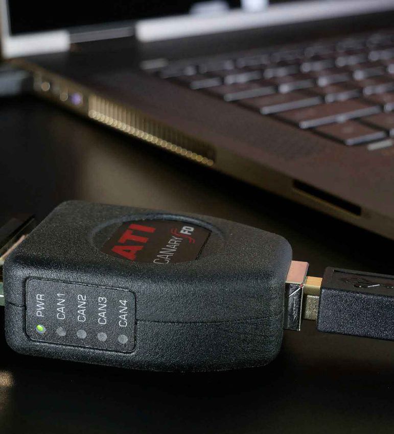
MEASURE • CALIBRATE • DEVELOP • OPTIMIZE • SUCCEED • 25 •CANary
& CANary FD
Compact
CAN Interfaces
SUPPORTS
4
HIGH CCP
SPEED AND ROBUST CAN FD
XCP
TIMESTAMPED
DESIGN READY
CAN CHANNELS DAQ
The CANary communicates with the PC using Full-Speed USB (12Mbps) and has two high speed CAN and two
LIN channels. All channels are electrically isolated from the USB connection and have internal bus termination
which can be set or unset by VISION.
The CANary FD is designed to handle the increased data available on CAN FD networks while retaining all the
features of the standard CANary. The CANary FD easily connects to PC over USB that provides a simple method
to acquire CAN data with VISION using any of the 4 galvanically isolated channels.
Supported devices include:
• ATI data acquisition hardware; EMX series, EDAQ series, Voltage Output
Module (VOM), and Vehicle Information Display (VID)
• ASAM communication protocols (CCP/XCP) typically used for calibration,
monitoring, and flashing of ECUs
• Generic CAN devices that utilize database files
The J2534/2-2019 API allows usage
of multiple CAN channels with
3rd party software applications
and maintains support for the
GMW17753 method.
• 26 • MEASURE • CALIBRATE • DEVELOP • OPTIMIZE • SUCCEEDCANary CAN Interface
CANary and CANary FD both use
multiple channels to bridge full
bandwidth CAN data between ATI’s data
acquisition hardware, ECUs, or other
CAN devices that are compatible with
VISION Software.
Key features for CANary include:
• 2 high speed CAN channels electrically isolated from channel to USB
• 2 LIN channels supporting M/S mode
• Both CAN channels handle high bus loads simultaneously
• Advanced time synchronization of ATI DAQ Hardware
• Micro robust design
Key features for CANary FD include:
• 4 high speed CAN/FD channels
• All 4 channels are galvanically isolated from channel to channel as well as
channel to USB
• Capable of both ISO CAN FD and non-ISO CAN FD
• Supports ATI Optimized DAQ when using the CANary FD with VISION and
ATI DAQ hardware
• Mechanically switchable CAN termination on each channel
• SAE J2534 drivers available
• USB/DB9-M physical connections
MEASURE • CALIBRATE • DEVELOP • OPTIMIZE • SUCCEED • 27 •CANverter CAN I/O Device
CANverter
I/O module
SUPPORTS
COMPACT
& CAN
COST
BIDIRECTIONAL
CAN TO I/O
CONVERSION
EFFECTIVE
DATABASE
FILES
IP65
RATED
The CANverter is a compact and cost effective I/O module suitable for Key CANverter I/O module
any high-speed physical layer CAN network. Used globally, this well-proven features include:
device can either send a message on a CAN bus or translate CAN data • Bidirectional CAN to I/O conversion
to an external acquisition system. • Compact and cost effective
• Supports CAN database files
Produced in high-quality ABS plastic, CANverter’s light weight and compact • Easy drag and drop
size makes it portable and simple to install just about anywhere.
Features:
• Converts CAN bus data to analog voltages or digital signals or PWM output
• Converts analog or digital inputs to CAN data
• Easy setup via the CANverter Configuration Software (using a .dbc or .uef
database, drag and drop signals onto the desired pin for quick configuration)
CANverter is a versatile
I/O module featuring
high-speed CAN network
and RS-232 configuration
ports.
• 28 • MEASURE • CALIBRATE • DEVELOP • OPTIMIZE • SUCCEEDATI & KVASER CAN bus Interfaces & Loggers
ATI & Kvaser
POWERFUL
CAN FD
READY
LOGGING
CAPABLITIES
WIRELESS
CONNECTIVITY
ATI offers it’s own branded and standard Kvaser CAN bus interface Compared to competitors,
products to complement its line of tools for any application requiring Kvaser interface and logger products
access to the CAN bus via a PC. These products provide a competitively offer these advantages:
priced, easy to use, flexible solution for network interfacing with VISION or • Kvaser’s universal, easy to use
CANLab Software. Kvaser’s product range is all based on the same API, API for both software developers
CANlib. Write to just one API and use any product on any platform. and the end client
• Free software, free updates
Select from three main product areas. USBcan units offer multi-channel USB and free support
interfaces for the CAN bus, while the Leaf series of products provide a single • Swedish innovation and Italian
channel USB interface for CAN with a range of features and price points. product housing design
Finally, products such as the Kvaser Memorator allow you to log data without • Strong commitment to
a PC, and then use the PC to extract network messages. Professional versions of R&D investment
any Kvaser product offer Magisync™, Kvaser’s software time stamp, to time-align • ATI branded devices offer extra
multiple CAN transceivers. Broader temperature ranges, higher speeds, increased functions compared to Kvaser
bandwidth and higher levels of accuracy differentiate Kvaser’s professional products. equivalents
ATI’s Kvaser range
of CANbus interfaces
and loggers offer D-sub,
J1939 and even 5-pin NMEA
approved CAN connectivity.
MEASURE • CALIBRATE • DEVELOP • OPTIMIZE • SUCCEED • 29 •DASH4ATI Data Display
DASH4ATI
Decode and
Display CAN
Data
The DASH4ATI from Race Technology is a compact and highly Key DASH4ATI features include:
configurable data display. The DASH4ATI can connect directly to CAN • Easy to configure with their PC
using DBC files to decode and display CAN variables. When connected to config tool
an ECU interface DASH4ATI can display all the decoded ECU parameters. • Works with DBC files. Multiplex
A sealed, compact and tough aluminum housing makes it a perfect fit for mode & J1939
test drive, test track, test cell and rig environments. • Setup five different screens
• Show number, text, bars, & graphs
Since the DASH4ATI uses graphics display, any combination of variables, text • CAN send by button, to trigger other
and even simple graphs can be placed anywhere on the screen. hardware or external applications
• Alarm function – warning LEDs
• Use together with supported CAN
data loggers
DASH4ATI features 2 rows
of very high brightness
multicolour LEDs.
• 30 • MEASURE • CALIBRATE • DEVELOP • OPTIMIZE • SUCCEEDTest Cell Products
MEASURE • CALIBRATE • DEVELOP • OPTIMIZE • SUCCEED • 31 •NS-1 Network Switch
NS-1
Revolutionary
Network
Switch
The NS-1 Network Switch is a 6-port Gigabit Ethernet switch that is Key NS-1 features include:
designed to meet the needs of using Ethernet devices in development • (6) 10/100/1000Mbps Gigabit Ethernet
vehicles and industrial applications. It provides a unique combination of ports
features not found in most commercial and industrial ethernet switches. • Compatible with standard Ethernet
devices
The automotive surge tolerant wide operating voltage of 6 to 36VDC allows the • Supports IEEE-1588 Precision Time
NS-1 to be reliably powered from a vehicle power system without fear of power Protocol (PTP) in hardware on all 6 ports
dropouts even during engine crank. Most commercial and industrial switches • Supplies Power over Ethernet (PoE) on
require minimum 12VDC power and are not suitable for being directly powered all 6 ports
from vehicle power systems. • Automotive surge tolerant wide operating
voltage of 6 to 36VDC
The NS-1 can be used out-of-the-box with all standard Ethernet devices and • Wide operating temperature range for hot
does not require VISION or any other software to operate or configure. and cold weather testing
• Fan-less design for high reliability
• Lemo and Phoenix terminal block power
connector options
The NS-1 Network Switch
takes PoE further by offering
30 watts per bank (1-3 and
4-6)
• 32 • MEASURE • CALIBRATE • DEVELOP • OPTIMIZE • SUCCEEDAE-100 Automotive Ethernet Adapter
AE-100
Plug and Play
Automotive
Ethernet
Adapter
AUTOMOTIVE
ADAPTER
The AE-100 Automotive Ethernet Adapter is a physical layer media Key AE-100 features include:
converter from standard 100Base-T Ethernet to 100Base-T1 Automotive • Interfaces standard Ethernet
Ethernet (OPEN Alliance BroadR-Reach (OABR) compatible). The AE-100 devices to 100Base-T1 Automotive
can be used out-of-the-box with all standard Ethernet devices and does not Ethernet
require any software to operate or configure. • 100Mbps pass-through data rate
• Wide -40 to +85°C operating
When comparing the AE-100 to other Automotive Ethernet Adapter solutions, temperature for in-vehicle
ATI’s adaptor is more compact and robust. Some solutions on the market require usage including hot/cold weather
power via USB thus adding the inconvenience of needing a computer close by testing
or a 5V DC adapter. The AE-100 benefits from Power over Ethernet (PoE) which • AE-100 can be powered by PoE
drastically simplifies wiring and makes it a plug and play standalone solution. (Power over Ethernet), such as from
the ATI NS-1 Network Switch,
simplifying wiring
• Automotive surge tolerant wide
operating voltage of 6 to 36VDC,
if PoE not available
Physical switch to select
Master/Slave mode avoids
auto-negotiation start-up
delay
MEASURE • CALIBRATE • DEVELOP • OPTIMIZE • SUCCEED • 33 •PICOTURN Rotational Speed Sensor
PICOTURN
Compact
Controller for
Turbochargers
TEST LEMO
ROBUST
DESIGN
CELL IP67
RATED
Connector
The PICOTURN® PTCM is a compact controller for turbocharger Key PTCM features include:
rotational speed sensors. Rated as IP67 proof, it is ideal for on vehicle • Compact size
fitments, yet is capable of minimum compressor wheel speed measurement • Adjustable number of vanes
of just 200 rpm, to a maximum of 400,000 rpm. • Designed for underbonnet use
• IP67 rating
The PICOTURN PTCM consists of a sensor with a 1.5m cable, a compact,
ruggedised signal-conditioning box, plus a lead for output and power supply.
Both the sensor and PTCM box are rated as IP67 proof if connected and
installed as per PICOTURN’s recommendations, making it ideal for underbonnet
fitments. The PTCM is capable of compressor wheel speed measurement up to
400,000 rpm with a minimum operating speed of 200 rpm.
The PICOTURN system benefits from high sensitivity, allowing a large distance
between sensor and the rotating vanes in the range of 1 mm at 0.6mm vane
thickness. Various sensors are available to accommodate numerous user cases
differentiated by the length and thread of the sensor head. The PTSM-H series
benefits from enhanced sensitivity, enabling use with titanium wheel and other
critical applications where higher temperatures are a priority.
• 34 • MEASURE • CALIBRATE • DEVELOP • OPTIMIZE • SUCCEEDTest Cell Products
IGTM SmartTach
Ignition Timing Meter Module
SPECIALTY PROGRAMMABLE ANALOG ROBUST
PRODUCT OUTPUT VOLTAGE DESIGN
OUTPUT
SmartTach Module ATI has developed unique products that satisfy
Universal speed measurement made easy with specific test cell or dynamometer challenges.
ATI’s SmartTach. The SmartTach takes pulse output These highly accurate products measure engine timing
from Engine position sensors, Dyno Encoders, (IGTM) or speed (SmartTach) in convenient ways to
Ignition drivers and other sources and provides provide information that otherwise may not be available.
a scaled analog speed output.
The SmartTach can easily handle missing tooth • Satisfy a unique need
wheels and multi-strike ignition systems that cause • Rugged construction
problems with Frequency to Voltage conversions. • Resistant to extremes of temperature
Use the SmartTach to also measure frequency, • High levels of reliability
pulse width or duty cycle.
Ignition Timing Meter
ATI’s Ignition Timing Meter (IGTM) is a precision
timing measurement instrument designed for
engine development and testing.
Measure ignition, camshaft or injector timing with
an accuracy of +/-0.05 degrees for steady-state and
transient testing. The IGTM-2000 provides an easy
means for data acquisition systems to collect real-time
measured ignition timing on spark ignited engines.
MEASURE • CALIBRATE • DEVELOP • OPTIMIZE • SUCCEED • 35 •Comprehensive ongoing
Training
ATI offers hands-on training to its customers globally. The courses offered are designed to gain a complete
understanding of ATI’s product concepts, functions, and features. Through instructor led demonstrations and
hands-on simulations, attendees will be able to apply this newly-acquired knowledge directly to their skillset.
ATI training classes can be conducted on-site or virtually at your convenience. To determine your training needs
or to schedule training, please contact your local ATI office.
Examples of ATI’s Most Popular Classes:
Advanced VISION ECU Interfaces
Focus on time-saving using the advanced features • Discover how serial interfaces are used in
offered by VISION, including: the calibration of and data acquisition from ECUs
• Customization • Review function and capabilities of each type
• Calibration Manager of interface
• Advanced table views and templates
Introduction to CANLab
Rapid Prototyping Basics This class covers initial set up and use of ATI’s
• No-Hooks software set up overview CANLab software. Learn more about using
• Perform real-world modification of ECU CAN with VISION, CAN Message functionality,
parameters and algorithms and configuring CAN interface hardware.
• Discover RP functions that make Practical examples include:
this patented product unique
• Review real-world examples • Monitoring, recording, and sending
to expand the capabilities of your CAN messages
own processes • Filtering and replaying CAN messages
• Using CAN Database (dbc) files
Scripting • Overview of CANLab Scripting
• Overview of scripting
• Create individualized tools to automate
custom activities or repetitive tasks
• Review examples of scripting techniques
to improve productivity
• 36 • MEASURE • CALIBRATE • DEVELOP • OPTIMIZE • SUCCEEDRapid on-site support
Worldwide
In addition to free product training, ATI prides itself on delivering a reactive global support service
that recognizes that your time is precious, enabling your team to maximize productivity with confidence.
For longer-term projects a comprehensive on-site support service is also available on request
globally for our major OEM and Tier One partners.
• Typical support emails answered within one hour
• Two week average repair
• On-site support available worldwide
• Free, ongoing product training
• Free, ongoing software updates
and feature additions*
*Current ATI SW Maintenance and Support required 4
5
1 2
1. USA - Accurate Technologies Inc. 3
Novi, Michigan 8
6
2. France - Accurate Technologies SAS
7
Futuroscope-Chasseneuil
3. Germany - Accurate Technologies GmbH & Co KG
München
4. Sweden - Accurate Technologies AB
Mölndal
5. United Kingdom - Accurate Technologies (UK) Ltd.
Hatley St George
6. China - Accurate Technologies China
Beijing
7. India - ATI Accurate Technologies India Private Ltd.
Bangalore
8. Japan - ATI Worldwide LLC
Tokyo
Photo - courtesy Delta Motorsport.
MEASURE • CALIBRATE • DEVELOP • OPTIMIZE • SUCCEED • 37 •Global Offices India
ATI Accurate Technologies India Private Ltd.
China Unit No S-5B & S-6B,
Accurate Technologies China Alpha Block 2ndFloor
TUS Star Building Sigma Soft Tech Park
Room A308 No7, Whitefield Main Road
Global Headquarters Shuangqing Road Jia #79 Ramagondanahalli
Haidian District Bangalore
Accurate Technologies Inc. Beijing Karnataka – 560066
26999 Meadowbrook Rd. China 100085 India
Novi, Michigan 48377 Phone: +86-138-1023-6357 Phone: +91 80 41255752
USA sales_cn@accuratetechnologies.com sales_in@accuratetechnologies.com
Phone: +1 248 848 9200 support_cn@accuratetechnologies.com support_in@accuratetechnologies.com
Fax : +1 248 848 9016
sales_us@accuratetechnologies.com France Japan
support_us@accuratetechnologies.com Accurate Technologies SAS ATI Worldwide LLC
Batiment Arobase 2 Téléport 1 Miyako Shinjuku Building 902
Avenue du Futuroscope 86360 Nishishinjuku 1-1-6
Futuroscope-Chasseneuil Shinjuku-ku
Vienne Tokyo 160-0023
France Japan
Phone: +33 (0) 1 72 76 26 10 Phone: +81 3-6276-8950
Fax: +33 (0) 1 72 76 25 99 Fax: +81 3-6276-8951
sales_fr@accuratetechnologies.com sales_jp@accuratetechnologies.com
support_fr@accuratetechnologies.com support_jp@accuratetechnologies.com
Germany Sweden
Accurate Technologies GmbH & Co KG Accurate Technologies AB
Lilienthalstrasse 27 Flöjelbergsgatan 14 C
85399 Hallbergmoos 431 37 Mölndal
Germany Sweden
Phone: +49 811 889 97351 Phone: +46 (0) 31-773-7140
Fax: +49 811 889 97379 sales_se@accuratetechnologies.com
sales_de@accuratetechnologies.com support_se@accuratetechnologies.com
support_de@accuratetechnologies.com
United Kingdom
Accurate Technologies (UK) Limited
Unit 7
St. George’s Tower
Hatley St George
Cambridgeshire
SG19 3SH
UK
Phone: +44 (0) 1767-652-340
Fax: +44 (0) 1767-652-341
www.accuratetechnologies.com sales_uk@accuratetechnologies.com
support_uk@accuratetechnologies.com
ATI - Your Global Measurement, Calibration and Diagnostics Partner
With a quarter of a century of experience in developing cutting-edge
software and hardware solutions for the measurement, calibration and
diagnostics (MCD) sector, Accurate Technologies Inc.’s (ATI’s) extensive
product portfolio is used globally by major OEMs and Tier One clients
across a wide variety of powertrain formats in the automotive,
defense, marine and aerospace sectors.
Information is provided on an “as is” basis and could
include technical, typographical or other errors. Accurate
Technologies Inc. makes no warranties, representations,
or guarantees of any kind, express or implied, including but
not limited to, accuracy, or completeness of the information,
content, and products.
Ref. Measurement, Calibration & Diagnostics Product Range & Corporate Overview 07/2021You can also read