BLANKET AND WALLPAPER LININGS DESIGN AND INSTALLATION MANUAL - Thermal Ceramics
←
→
Page content transcription
If your browser does not render page correctly, please read the page content below
BLANKET AND WALLPAPER LININGS
               DESIGN AND INSTALLATION
                       MANUAL

Thermal Ceramics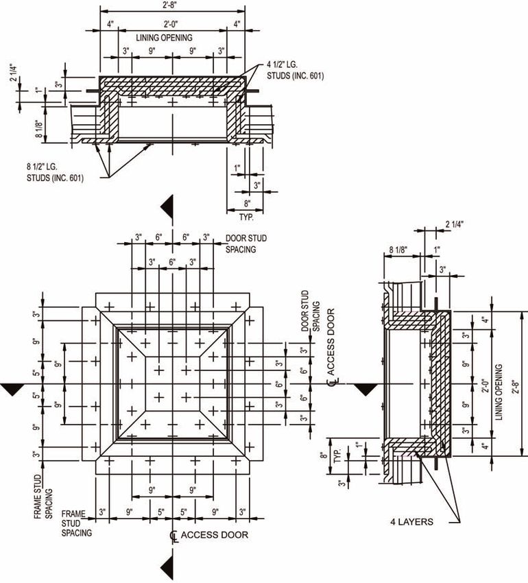
TABLE OF CONTENTS
   A. Preface
      Introduction                                                     3
   B. Blanket and Wallpaper Linings
      1. General
         1.1 Lining Considerations                                     4
         1.2 Site Preparation                                          4
         1.3 Stud Welding                                              4
         1.4 Butt Joint Construction                                   5
         1.5 4” Overlap Construction                                   6
         1.6 12” Overlap Construction                                  7
      2. Installation
         2.1 Geberal                                                   8
         2.2 Flue Opening                                              9
         2.3 Corners                                                   9
         2.4 Burners                                                   9
         2.5 Miscellaneous                                            10
   C. Glossary of terms                                               12
    List of Figures
       Figure 1    Anchoring System                                    4
       Figure 2    Butt Joint Construction                             5
       Figure 3    Vertical Stud Layout                                6
       Figure 4    4” Overlap Construction                             6
       Figure 5    12” Overlap Construction                            7
       Figure 6    Corner Details                                      7
       Figure 7    Blanket Lining for Flues                            8
       Figure 8    Alternate Corner Detail                             9
       Figure 9    Burner Wrap                                         9
       Figure 10 Typical Lining Thickness Transition Detail            9
       Figure 11 Typical Wallpaper Lining Detail for an Access Door   10
    List of Tables
       Table 1     Stud Estimate                                       6

May 2003                                      Thermal Ceramics         Page 2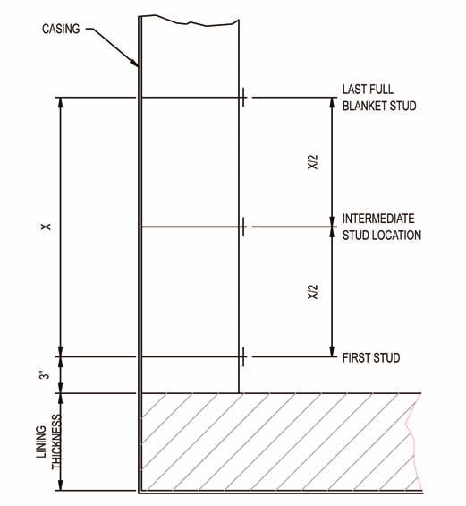
DESIGN & INSTALLATION MANUAL
                                                                               BLANKET AND WALLPAPER LININGS

INTRODUCTION                                                  BLANKET AND WALLPAPER LININGS
Over the past 75 years, Thermal Ceramics has proven           Our line of ceramic fiber blanket products features low
itself to be a world leader in solving problems for heat-     thermal conductivity, excellent thermal shock resistance
intensive industries.                                         and low heat storage capacity. Available in a wide range
                                                              of temperature and density compositions, Thermal
The refractory ceramic fiber manufactured by Thermal
                                                              Ceramics refractory ceramic fiber blankets contain no
Ceramics is a highly versatile material. It can be spun or
                                                              organic materials that could contaminate furnace atmos-
blown into bulk, air-laid into a blanket, folded into mod-
                                                              pheres at elevated temperatures. Thermal Ceramic blan-
ules, formed into monolithic modules (Pyro-Bloc®), con-
                                                              ket products can be supplied from stock in a variety of
verted into boards and shapes, die-cut into gaskets, twist-
                                                              densities, thicknesses and roll widths.
ed into yarns, woven into rope and cloth, and blended
into liquid binders for coatings and cements. With this       The following procedures are intended to provide instruc-
wide range of products, Thermal Ceramics can provide          tion on how to install blanket/wallpaper linings success-
exactly the right product, or engineered system to fit your   fully. It is important that certain installation considerations
requirements. Thermal Ceramics has an experienced             are taken into account during the design process. The
staff of refractory specialists to assist you in product      procedures presented here will apply to the majority of
selection, system design, and installation techniques.        cases, but do not attempt to address all the situations that
                                                              might be encountered. The specific topics which will be
Thermal Ceramics has enjoyed great success with its
                                                              discussed are:
ceramic fiber products due to their cost-effectiveness and
excellent insulating properties. They are lightweight and      • Anchoring Systems and Layout
have low thermal conductivities, excellent resistance to
                                                               • Tools and Equipment
thermal shock, outstanding electrical resistivity, and good
acoustical properties.                                         • Installation Designs

This Design and Installation Manual is intended to give
the designers, installers, and users of Thermal Ceramics
ceramic fiber products a broad range of information on
how to select the most appropriate fiber system for a par-
ticular application, necessary design criteria, and how to
correctly install the selected system.

PLEASE NOTE: This manual has been designed to eas-
ily accommodate new or revised information. Holders of
the manual are advised to keep their address current with
the Advertising and Sales Promotion Department at
Thermal Ceramics in Augusta, Georgia. Any questions or
comments regarding this manual should be addressed to
your local Thermal Ceramics representative.

December 2002                                     Thermal Ceramics                                                  Page 3
1. G E N E R A L Stud patterns vary across the width of the blanket accord-
1.1 Anchoring Systems ing to the type of installation desired. For instance, butt
joint applications require a 9"-9"-51/2" stud pattern; 4"
overlap applications require a 10"-10"-10" stud pattern,
while 12" overlap applications require a 6"-6"-6" stud pat-
tern.
Anchor Alloy Selection - The following use limits are
suggested by API and are based solely on furnace oper-
ating temperature. If sulphur and/or other contaminants
are present, a change in the anchor alloy selection may
be required.
Furnace 304SS 316SS 309SS 310SS Inconel
Temperature 601
1400°F X X
1500°F X
1700°F X
2000°F X
Figure 1 - Anchoring System
1.2 Tools and Equipment The 316SS alloy anchors have provided greater resis-
The basic equipment required for the installation of a tance to sulphur and should be considered in these situ-
ceramic fiber blanket lining includes the following: ations.
• 300 amp welding machine • rubber bands (1/4" x 3") For operating conditions above 2000°F, ceramic cone
• stud welding guns • lighting anchors or ceramic spike anchor systems can be consid-
ered. For more information on these designs, contact
• chalk line & soapstone • scaffolding
your Thermal Ceramics representative.
• tape measure • 3" side grinders
• 6" butcher knives • plumb line 1.4 Butt Joint Construction
• 4' straight edge The pattern for the horizontal spacing with butt joint con-
struction is 9"-9"-51/2". This will be across the width direc-
1.3 Anchor Layout
tion of the blanket. The use of 51/2" instead of 6" with a
The anchor layout should be made on the inside of the 24" wide blanket ensures a slight compression of the
casing, making sure that the anchor system is appropri- joint. A template can be made up to assist with the lay-
ately placed for the blanket lining. Typically, the anchor out. Repeat this pattern along the top and bottom of the
layout begins at the endwall of the unit. Special attention wall as long as full width blankets can be used and strike
should be given to the corner anchors to ensure enough the vertical chalk lines by connecting the corresponding
distance from the adjacent wall. marks.
The anchor layout is based upon the exposed or hot face When intersecting another wall, the spacing is adjusted
layer of blanket without regard to any of the back-up lay- to ensure that the first stud row from the adjacent wall will
ers of blanket. Ensure that all joints in successive layers be 3" plus the lining thickness. Measure from the last full
of blanket are staggered or offset. Also, there should be stud row to the corner and subtract 3" plus the lining
a 3" maximum distance between the last row of studs and thickness. Take one half of this distance to determine the
the end or edge of the blanket. In the majority of cases, location of the intermediate stud row. See Figure 2.
the required stud length will be the same as the nominal
To obtain the vertical spacing between stud rows start in
thickness of the blanket lining. The layout should include
the same back wall corner. Measure down from the roof
a minimum hot face blanket width of 12".
3" plus the thickness of the lining and mark. The vertical
The maximum length of the hot face blanket layer should spacing between each of the remaining rows is 14". The
not exceed 121/2'. This will prevent shrinkage tears from only exception to this will be the last two stud rows near-
developing along the length of the blanket. est the floor. These will be located in the same manner
as described earlier for intersecting another wall. To
May 2003 Thermal Ceramics Page 4DESIGN & INSTALLATION MANUAL
BLANKET AND WALLPAPER LININGS
complete the vertical spacing, make the same measure- ating temperature is equal to or greater than 1900°F. At
ments down the opposite corner and mark each. The the opposite end of the roof, place than last stud row in
horizontal lines can now be struck to complete the grid. 3" plus the thickness of the lining. Then center the sec-
ond row between this and the last full row.
This same procedure should be used for all the walls in
the furnace and then recheck all corners to ensure that Stud Placement - When the layout for the furnace is
the first stud row in each case is 3" plus the lining thick- completed, an anchor should be welded at each inter-
ness. section of the chalk lines. Some of the anchor locations
may require grinding to ensure a good weld if rust, paint,
In order to start the stud layout for roof or arch, the verti-
grease, etc. is present. The Kao-Lok anchor may be stik-
cal lines on the end walls will be used for one set of mea-
welded or welded with a stud gun. If a stud gun welding
surements. These will provide the 9"-9"-51/2" pattern
system is used, test welds should be made periodically to
required along the width of the blanket. The chalk line
ensure the equipment stays properly adjusted.
can be lined up with these marks and the lines running
the length of the furnace struck. The stud spacing run- All welds should be visually inspected and approximately
ning along the length of the furnace will start from one 5 to 10% should be randomly selected for testing. The
endwall. The first stud row is located by measuring in 3" most common test is a “bend” test which consists of
plus the thickness of the lining. Subsequent stud rows bending the stud over approximately 30 degrees from the
will be located every 12" if the furnace operating temper- casing and then straightening it back to the perpendicu-
ature is less than 1900°F, or every 9" if the furnace oper- lar. A poor weld will fail during this test. Where the stud
Figure 2 - Butt Joint Construction
December 2002 Thermal Ceramics Page 5weld failed, the casing should be ground smooth to vides a starting point for the other vertical lines.
remove all traces of the initial weld and a new stud weld-
1.5 4" Overlap Construction
ed.
The 4" overlap design is frequently used in furnaces
The equipment needed includes a stud gun, a control unit
operating above 1900°F. The stud pattern is laid out with
and an adequate DC welding current supply. The stud is
regard for the hot face blanket layer only. The stud pat-
loaded into the properly sized chuck, the ceramic ferrule
tern along the width of the blanket is different from the
is placed in position over the end of the stud and the gun
other designs. In the 4" overlap construction, this pattern
is properly positioned for welding. The gun, control unit
should be 10"-10"-10".
and welding machine are connected as shown in Figure
10 or 11 for welding. Unlike the layout for butt joint construction, it is easier
with overlap designs to begin the layout at the vertical
The anchor layout for the furnace walls should start from
center line of a wall. Mark a vertical chalk line 5" on either
side of the wall center line. Strike the other vertical chalk
lines every 10 " back toward each corner. When this wall
intersects with other walls, follow the same procedure as
described for butt joint construction. To locate the verti-
cal spacing between stud rows on the walls, start at the
top of one backwall corner. Measure down from the roof
3" plus the thickness of the lining and mark. Continue to
measure down the wall and mark every 14" if the furnace
operating temperature is less than 1900°F, every 12" if
the furnace operating temperature is equal to or greater
than 1900°F. The last two stud rows, where the wall
meets the floor, are located in the same manner as
described previously for intersections of this nature.
Repeat these measurements at the opposite end of the
wall and strike the chalk lines by aligning the respective
marks.
The procedure is repeated in an identical manner on the
roof.
1.6 12" Overlap Construction
Another method of installing blanket/wallpaper linings is
Figure 3 - Vertical Stud Layout to use the 12" overlap technique. The stud layout is car-
ried out in the same manner as previously described for
the top of one back or endwall corner. To begin the lay- the 4" overlap. The only difference is the horizontal stud
out for the horizontal spacing between stud rows, mea- spacing. When designing for a 12" overlap use a hori-
sure in 3" from the corner plus the lining thickness and zontal stud spacing of 6" between each row.
mark. Using a plumb line, strike a vertical line from the
above measurement down the sidewall. This line pro-
Butt Joint 4” Overlap 12” Overlap
Construction Construction ConstructionDESIGN & INSTALLATION MANUAL
BLANKET AND WALLPAPER LININGS
Figure 4 - 4” Overlap Construction
Figure 5 - 12” Overlap Construction
December 2002 Thermal Ceramics Page 72. INSTALLATION set or staggered from underlying layers. As a result, in
this example, the initial blanket installed on the first and
2.1 General
third layers should be cut approximately in half to form a
The minimum number of blanket layers which will achieve 12" strip.
the desired effect should be used to reduce installation
Using a minimum of three people, start with the first layer
cost. In most installations, it is convenient to roll out the
of 2", 4# blanket in the back corner of the furnace. One
blanket vertically, but horizontal applications can also be
person should hold the roll of blanket while the other two
used. The direction of the gas flow should be taken into
pull out approximately 6 feet of material. For this exam-
account when setting the orientation of the joints.
ple, let the edge of the blanket hang down the sidewall
Ceramic fiber has relatively low resistance to erosion approximately 4' from the roof and then push the blanket
from high velocity gas with abrasive particles and over the Kao-Lok studs. At the corner, be sure to mold
mechanical or physical abuse. In these layered designs, the blanket into the corner before pushing onto the studs.
it is recommended that the hot face blanket be 1" thick
To install the blanket on the roof, the person with the roll
and 8 lb/ft3 density. Depending upon the severity of these
of blanket should place it over his head and walk back-
conditions, the durability of the lining can be increased by
wards slowly, letting the blanket feed off the roll in a
applying a coating of rigidizer (temperature limit of
straight line, while keeping the roll against the tips of the
1800°F) to the hot face of the blanket.
studs. The other two workers should push the blanket
The hot face layers should be designed with proper over the Kao-Lok studs and stretch rubber bands
allowance for shrinkage. For more information on shrink- between the studs to temporarily prevent the blanket from
age of ceramic fiber, refer to the publication “Technical falling. The blanket should be pushed carefully into place
Aspects of Ceramic Fiber” (M140). without stretching or tearing.
A 6" thick lining is one of the most commonly used in Install enough of the first layer of blanket to allow the sec-
industry and will be used for the following example. ond layer to be started, while staggering the joints formed
Our lining example shall consist of: along the length edge of the blanket. The full 24" wide
blanket used on the second layer will automatically cover
2", 4# ceramic fiber blanket the joint on the first blanket layer by 12". When placing
2", 4# ceramic fiber blanket the blanket, always butt adjoining blankets together tight-
1", 6# ceramic fiber blanket ly.
1", 8# ceramic fiber blanket The end of the second blanket layer should be started at
(Hot Face Layer) the point on the sidewall approximately 3' down from the
It is important to note that minimal cutting of the hot face roof. In this way, there will be a 12" offset at the end of the
blanket between successive layers. Each blanket layer
should be staggered in this way.
After a sufficient area has been covered with the second
blanket layer, the third layer can be started following the
same techniques to ensure all the joints are staggered.
On thick wallpaper roof applications, a Kao-Lok speed
clip can be installed prior to the hot face layer of blanket
to help carry the weight of the lining.
At this point, the hot face blanket layer can be installed.
In most situations it is advisable to install the roof hot face
layer first, followed by the side and endwall hot face lay-
ers. Compress the blanket, insert and rotate a Kao-Lok
washer onto each Kao-Lok stud to secure the blanket in
place.
2.2 Flue Openings
Figure 6 - Corner Details Flue openings in wallpaper linings can best be accom-
blanket is desirable and that blanket joints should be off- modated by cutting four extra pieces of hot face blanket
May 2003 Thermal Ceramics Page 8DESIGN & INSTALLATION MANUAL
BLANKET AND WALLPAPER LININGS
material as shown in Figure 7. In this way, the opening
can be effectively lined without allowing a straight-
through joint. This overlapping of as many layers as pos-
sible ensures the best possible seal of the blanket joints.
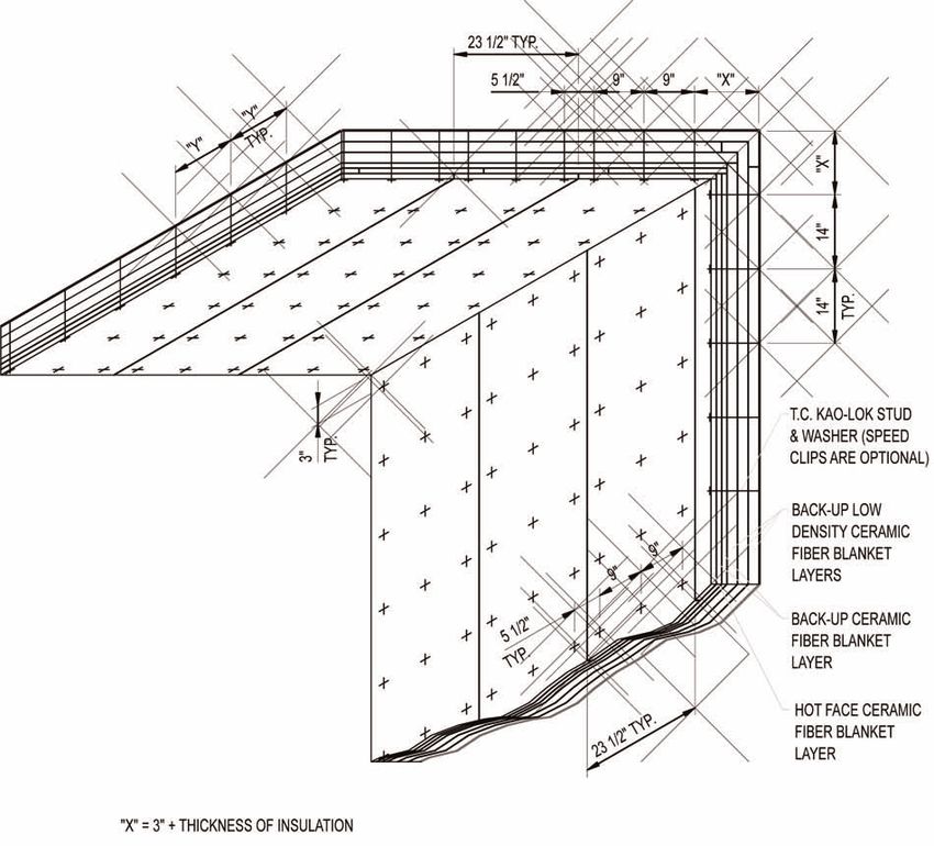
2.3 Corners
In Figure 8 an alternative method for handling corners is
illustrated. The additional strip of hot face blanket mate-
Figure 8 - Alternate Corner Detail
Figure 7 - Blanket Lining for Flues
rial provides an additional overlap resulting in a well
sealed joint.
2.4 Burners
In those areas where burners are involved, special atten-
tion must be paid to the fiber arrangement around the
burner opening. The recommended arrangement, which
is shown in Figure 9, consists of a 1" thick, 8# hot face
ceramic fiber blanket material that is used to wrap the
burner block prior to the installation of the blanket on the
wall. As the blanket is installed on the wall, each layer
should be butted tightly into this blanket wrap.
Figure 9 - Burner Wrap
December 2002 Thermal Ceramics Page 92.5 Miscellaneous
Other areas that will need careful attention
are doors and tapered sections. Figures 10
and 11 are included for use as a guide when
these areas are encountered.
For further information on Thermal Ceramics’
blanket/wallpaper designed linings, please
contact your local Thermal Ceramics Sales
Representative or the Technical Sales and
Service Department at (706) 796-4200.
Notice:
Some of the products described in this litera-
ture contain Refractory Ceramic Fiber (RCF)
and/or crystalline silica (cristobalite or
quartz). Based on experimental animal data,
the International Agency for Research on
Cancer (IARC) has classified RCF, along with
Figure 10 - Typical Lining Thickness Transition Detail
fibrous glasswool and mineral wool, as a possible human
carcinogen (Group
Figure 11 - Typical Walpaper Lining
2B) and respirable
Detail for an Access Door
crystalline silica as
a probable human
carcinogen (Group
2A).
To reduce the
potential risk of
health effects,
Thermal Ceramics
recommends engi-
neering controls
and safe work prac-
tices be followed by
product users.
Contact the
Thermal Ceramics
P r o d u c t
Stewardship Group
(1-800-722-5681) to
request detailed
information con-
tained in its MSDSs
and product litera-
ture and videos.
May 2003 Thermal Ceramics Page 10DESIGN & INSTALLATION MANUAL
G L O S S A RY OF TERMS
Amorphous: Having no definite crystalline structure or form. Lock Washers: Washers used in conjunction with Kao-Lok studs.
Back-up Insulating Material: The layer or layers of insulating They are slotted so that when pushed over the stud and then twist-
material that are located between the hot face insulating layer and ed 90° the washer is locked into place, other locking systems are
the outer casing. available, such as cone anchors. Lock anchors come in ceramics
or alloy metals to suit temperature requirements.
Blanket: A flexible unbonded ceramic fibrous insulating material of
reasonably determinate dimensions. Maximum Temperature Rating: The temperature which is used
by the industry as a loose classification of different grades of
Board: A substantially rigid or semi-rigid flat sheet produced by ceramic fiber. This is generally higher than the continuous use limit.
vacuum forming.
Module: A prefabricated unit which can be applied as a lining block
Bulk Fiber: Ceramic fibers in the “as-produced” state. to the inner face of a furnace structure.
Butt Joint: A ceramic fiber wallpaper construction joint where Mortar/Cement: A ceramic-based adhesive for attaching ceramic
edges of adjacent blankets meet. fiber products to other surfaces.
Cold Face Temperature: Term used to denote the outside casing Mullite: A crystalline phase of alumina-silica.
temperature.
Overlap Construction: A construction technique used to accom-
Continuous Use Limit: Long-term (continuous) temperature limit modate shrinkage in ceramic fiber or to improve velocity resistance
for a product installed as a lining. This temperature is based upon in which one edge of a blanket is lapped over an adjacent blanket
product shrinkage, specifically what is considered to be a “man- edge by 4" to 12" and shares a common anchor stud and washer.
ageable” or “controllable” shrinkage. This term is not to be confused
with temperature rating. Paper: A roll product produced from ceramic fibers and organic
binders on conventional paper-making machinery.
Cristobalite: A crystalline phase of silica which will begin to form
above 1800°F. Parquet: A method of installing modular edge-grained forms of
ceramic fiber so that the edge grain of one module is perpendicular
Devitrification: The phase transformation from glass to crystalline to the edge grain of the adjacent modules.
structure.
Rigidizing: The practice of applying an inorganic hardening agent
Edge-grain: The orientation of a fiber system in which strips of to the surface of ceramic fiber (by spray or brush) in order to
ceramic fiber blanket or felt are oriented perpendicular to the plane improve its velocity resistance.
of the furnace casing.
RCF: Refractory Ceramic Fiber.
Felt (Pressed): A flexible sheet product formed from ceramic
fibers and bonded with an organic binder. Shingled Joint: A method of applying double layers of ceramic
fiber blanket in such a way that half the width of each layer overlaps
Heat Loss: The term used to denote the amount of heat being lost half the width of the adjacent layer.
through a lining construction over time, measured in BTU/sq ft/min,
(watts/sq in). Shot: A glassy material formed during fiberization.
Heat Storage: The thermal property of a material wherein heat Textile: Cloth, tape, sleeving, tubing, or other forms manufactured
accumulates in the mass (which in refractories is a function primar- from ceramic fiber yarn.
ily of the material’s specific heat, mass, and temperature rise mea- Thermal Conductivity: The property of material to conduct heat -
sured in Btu/lb/°F (Cal/g/°C). measured in Btu flow per hour through a square foot of area across
Heat Transfer: The study of heat flow mechanisms - conduction, one inch of thickness Btu•in/hr•ft•°F (w/m •C°).
convection, and radiation. Thermal Resistivity: The property of a material to resist the flow
High Alumina Fiber: A ceramic fiber containing more than 90% of heat; the reciprocal of thermal conductivity.
alumina, giving a high use limit. Mullite fiber is also used in high Thermal Shock: A failure mechanism wherein sudden changes in
temperature applications. temperature bring sufficient thermal mechanical stress in a materi-
High Purity (HP) Fiber: A ceramic fiber produced from synthetic al to cause cracking or spalling. As a general rule, the thermal
alumina and silica. shock resistance of a material is greater as the strength and ther-
mal conductivity of a material increase and as the thermal expan-
Hot Face Insulating Material: The layer of lining insulating mater- sion and modulus of elasticity decrease.
ial that has at least one surface exposed to the full temperature of
the furnace gases. Turbulent Flow: Fluid flow in which the velocity of a given stream
of gas changes constantly both in magnitude and direction.
Kaolin Fiber: A ceramic fiber produced from calcined kaolin.
Vacuum Forming: A method of producing molded shapes and flat
Laminar Flow: The flow of a gas in which the gas stream moves board by converting fibers into a slurry and vacuuming them onto a
in straight lines parallel to the direction of the flow. screen former.
Layered Lining Wallpaper: Lining that is composed of several Veneer: Layer of ceramic fiber in either blanket or module form
layers and thicknesses of refractory ceramic fiber. which is attached to the hot face of a brick, module or monolithic
Linear Shrinkage: The amount of shrinkage which occurs along lining.
the length of a material after it has been subjected to elevated tem- Wallpaper Construction: The term used to describe a ceramic
peratures and then cooled - measured in percent of original prefired fiber lining construction technique where the blanket is installed on
length. a wall like a roll of wallpaper.
May 2003 Thermal Ceramics Page 11For further information, contact your nearest Thermal Ceramics technical sales office. You may also fax us
toll-free at 1-800-KAOWOOL, or write to Thermal Ceramics, P. O. Box 923, Dept. 140, Augusta, GA 30903.
Global Headquarters
Thermal Ceramics Global
L'Européen - Bât. C
2, rue Joseph Monier
92859 Rueil-Malmaison Cedex, France
T: +33 (0)1 47 16 22 23
F: +33 (0)1 47 16 22 40
E-mail: info@tc-global.com
Global Marketing Offices
Thermal Ceramics Americas
2102 Old Savannah Road
Augusta • Georgia • 30906
T: +1 (706) 796 4200
F: +1 (706) 796 4398
E-Mail: tceramics@thermalceramics.com
Thermal Ceramics Asia Pacific
28 Jalan Kilang Barat
Kewalram House
Singapore • 159362
T: +65 6273 1351
F: +65 6273 0165
E-mail: thermalceramics@tcasia.com.sg
Thermal Ceramics Europe
Tebay Road • Bromborough • Wirral
CH62 3PH • England
T: +44 (0) 151 334 4030
F: +44 (0) 151 334 1684
E-mail: marketing@thermalceramics.co.uk
Sales and Marketing Office Locations
North America South America
Canada Argentina
T: +1 (905) 335 3414 T: +54 (11) 4373 4439
F: +1 (905) 335 5145 F: +54 (11) 4372 3331
Mexico Brazil
T: +52 (555) 576 6622 T: +55 (11) 4178 1999
F: +52 (555) 576 3060 F: +55 (11) 4178 1675
United States of America Chile
Southeastern Region T: +56 (2) 854 1064
T: +1 (800) 338 9284 F: +56 (2) 854 1952
F: +1 (706) 796 4324 Colombia
Midwest Region T: +57 (222) 82935/82803
T: +1 (866) 785 2738 F: +57 (222) 82935/82803
F: +1 (866) 785 2760 Guatemala
Eastern Region T: +50 (2) 4733 295/6
T: +1 (866) 785 2763 F: +50 (2) 4730 601
F: +1 (866) 785 2764 Venezuela
Western Region T: +58 (241) 878 3164
T: +1 (866) 785 2765 F: +58 (241) 878 6712
F: +1 (866) 785 2782
w w w.thermalceramics.com
05.03/M141/1M COPYRIGHT © 2002 THERMAL CERAMICS INC.You can also read