Bridge Construction CERTIFIED TECHNICIAN PROGRAM - and Deck Repair - IN.gov
←
→
Page content transcription
If your browser does not render page correctly, please read the page content below
Indiana Department of Transportation

   CERTIFIED TECHNICIAN PROGRAM
       TRAINING MANUAL FOR
     Bridge Construction
      and Deck Repair

               Revised November 2021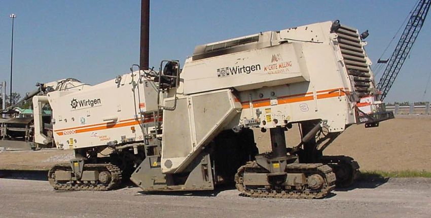
MANUAL DISCLAIMER
  The references in this manual are reflective of the 2022 standard specifications The material
  used in this manual is to be used for training purposes only. The Standard Specifications,
  Contract Information Book, General Instruction to Field Employees, and Construction
  Memos will need to be consulted for determining the current inspection procedures
  associated to the contract. Some of the procedures, field tests, and other operating
  procedures as described within this manual may be different than actual on-site procedures.

MATH INFORMATION
  1 foot = 12 inches    1 square foot = 144 square inches     1 cubic foot = 1728 cubic inches
  3 feet = 1 yard       9 square feet = 1 square yard         27 cubic feet = 1 cubic yard
  5280 feet = 1 mile    1760 yards = 1 mile
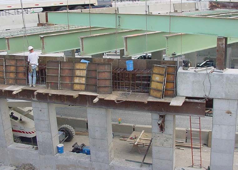
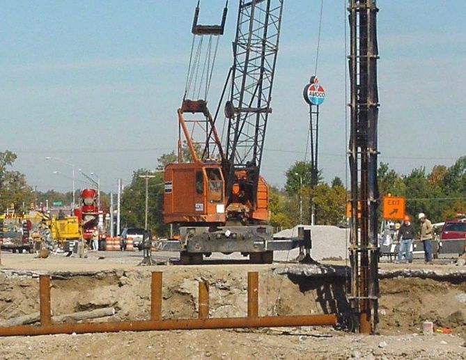
TABLE OF CONTENTS

                     BRIDGE CONSTRUCTION OVERVIEW ............................................................................................... 1-1
 TECHNICIAN DUTIES......................................................................................................................................................... 1-1
 BASIC BRIDGE TERMS....................................................................................................................................................... 1-1
    Substructure .......................................................................................................................................................... 1-1
    Superstructure ....................................................................................................................................................... 1-4
    Spans And Span Length ......................................................................................................................................... 1-5
    Simple And Continuous Spans ............................................................................................................................... 1-5
 BRIDGE PLANS ................................................................................................................................................................ 1-6
    Title And Index Sheet ............................................................................................................................................. 1-6
    Boring Data Sheets ................................................................................................................................................ 1-6
    Layout Sheet .......................................................................................................................................................... 1-6
    General Plan Sheet ................................................................................................................................................ 1-6
    Detail Plan Sheets .................................................................................................................................................. 1-7
    Bridge Summary And Estimate Of Quantities Sheets ............................................................................................ 1-7
    Standard Drawings ................................................................................................................................................ 1-7
    Contractor Plans Or Drawings ............................................................................................................................... 1-7
 CONSTRUCTION CONTROLS AND LAYOUT............................................................................................................................. 1-8
    Horizontal Controls ................................................................................................................................................ 1-8
    Vertical Controls .................................................................................................................................................... 1-8
    Bridge Construction Layout ................................................................................................................................... 1-9
                     FOUNDATIONS............................................................................................................................... 2-1
 STRUCTURE EXCAVATION .................................................................................................................................................. 2-1
    Soil Borings ............................................................................................................................................................ 2-1
    Cross Sections ........................................................................................................................................................ 2-2
    Classes Of Structure Excavation ............................................................................................................................ 2-2
    Limits of Excavation ............................................................................................................................................... 2-3
    Disposal of Excavated Material ............................................................................................................................. 2-4
    Preparation of Foundation Surfaces ...................................................................................................................... 2-4
    Subsoil Investigations ............................................................................................................................................ 2-5
    Dewatering Excavations ........................................................................................................................................ 2-5
    Cofferdam Construction ........................................................................................................................................ 2-6
 FOUNDATION PILING ....................................................................................................................................................... 2-7
    Types Of Piling ....................................................................................................................................................... 2-7
    Delivery And Acceptance ....................................................................................................................................... 2-7
    Pile Driving Hammers ............................................................................................................................................ 2-8
    Energy Output ..................................................................................................................................................... 2-10
    Bearing and Refusal............................................................................................................................................. 2-10
    Test Piling ............................................................................................................................................................ 2-12
    Driving Foundation Piles ...................................................................................................................................... 2-12
    Measurement and Payment ................................................................................................................................ 2-15
                        FORMS, FALSEWORK, AND REINFORCEMENT .............................................................................. 3-1
 FORMS .......................................................................................................................................................................... 3-1
    Basic Form Requirements ...................................................................................................................................... 3-1
    Form Plans ............................................................................................................................................................. 3-1
    Form Materials ...................................................................................................................................................... 3-2
Form Construction ................................................................................................................................................. 3-4
Installation of Form Ties and Spreaders ................................................................................................................ 3-5
Chamfer Strips ....................................................................................................................................................... 3-5
Keyways ................................................................................................................................................................. 3-5
Preparation For Concrete Placement .................................................................................................................... 3-6
Removal Of Forms ................................................................................................................................................. 3-6
FALSEWORK ................................................................................................................................................................... 3-6
Reinforcement ....................................................................................................................................................... 3-7
Reinforcement Details ........................................................................................................................................... 3-9
Delivery And Storage ........................................................................................................................................... 3-10
Installation of Reinforcement .............................................................................................................................. 3-11
Method of Measurement .................................................................................................................................... 3-13
Basis of Payment ................................................................................................................................................. 3-13
CONCRETE PLACEMENT ................................................................................................................ 4-1
CLASSES OF STRUCTURAL CONCRETE ................................................................................................................................... 4-1
CONCRETE PLANT INSPECTION ........................................................................................................................................... 4-1
Types of Plants....................................................................................................................................................... 4-1
Preparations for Concrete Placement.................................................................................................................... 4-2
Plan Review ........................................................................................................................................................... 4-2
Site Preparations ................................................................................................................................................... 4-2
Weather Restrictions ............................................................................................................................................. 4-2
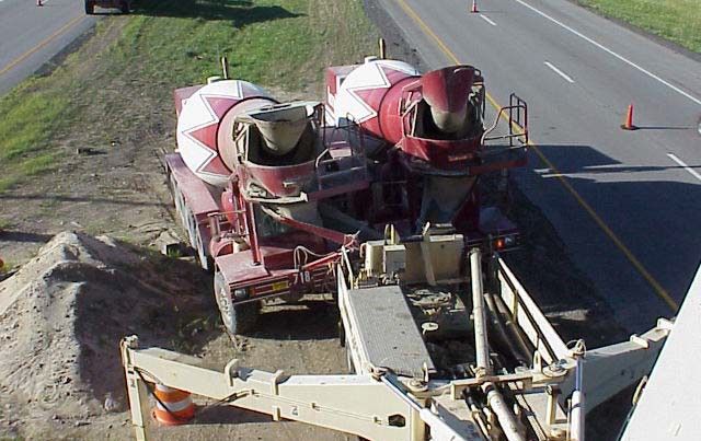
CONCRETE DELIVERY........................................................................................................................................................ 4-3
Delivery Equipment ............................................................................................................................................... 4-3
Delivery Tickets ...................................................................................................................................................... 4-3
FIELD TESTS ................................................................................................................................................................... 4-4
Recording Test Results ........................................................................................................................................... 4-5
CONCRETE PLACEMENT .................................................................................................................................................... 4-5
Segregation ........................................................................................................................................................... 4-5
Consolidation Of Concrete ..................................................................................................................................... 4-6
Construction Joints ................................................................................................................................................ 4-7
Special Cases ......................................................................................................................................................... 4-8
FINISHING CONCRETE SURFACES ........................................................................................................................................ 4-8
Finishing Bearing Areas ......................................................................................................................................... 4-9
Other Surface Treatments ..................................................................................................................................... 4-9
Curing Substructure Concrete ................................................................................................................................ 4-9
Cold Weather Curing ........................................................................................................................................... 4-10
METHOD OF MEASUREMENT AND BASIS OF PAYMENT ........................................................................................................ 4-10
BEARINGS AND STRUCTURAL MEMBERS ........................................................................................ 5-1
BEARINGS ...................................................................................................................................................................... 5-1
Expansion, Semi-Fixed, and Fixed .......................................................................................................................... 5-1
Bearing Design ...................................................................................................................................................... 5-1
Elastomeric Bearings ............................................................................................................................................. 5-3
Steel Bearings ........................................................................................................................................................ 5-3
Bearing Installation And Adjustments ................................................................................................................... 5-5
STRUCTURAL STEEL.......................................................................................................................................................... 5-6
Beams and Girders ................................................................................................................................................ 5-6
Approval of Structural Steel................................................................................................................................... 5-8
Structural Steel Plans............................................................................................................................................. 5-8
Delivery and Storage ............................................................................................................................................. 5-9
Erection of Steel Members................................................................................................................................... 5-10
Field Welding ....................................................................................................................................................... 5-13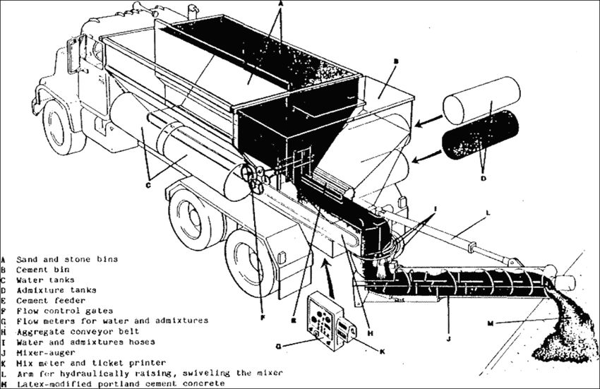
Measurement and Payment ................................................................................................................................ 5-14
CONCRETE MEMBERS .................................................................................................................................................... 5-14
Delivery, Storage, and Handling .......................................................................................................................... 5-15
Erecting Concrete Beams ..................................................................................................................................... 5-15
Final Approval of Concrete Members .................................................................................................................. 5-16
Measurement and Payment ................................................................................................................................ 5-16
BRIDGE DECKS .................................................................................................................................. 6-1
REFERENCES ................................................................................................................................................................... 6-1
GRADE CONTROL ............................................................................................................................................................ 6-1
Screed Elevations ................................................................................................................................................... 6-1
DECK FORMS.................................................................................................................................................................. 6-2
Approval of Falsework Plans ................................................................................................................................. 6-2
Types of Deck Forms .............................................................................................................................................. 6-2
Installing Deck Forms ............................................................................................................................................ 6-3
INSTALLATION OF SHEAR CONNECTORS................................................................................................................................ 6-4
DECK REINFORCEMENT .................................................................................................................................................... 6-5
ADJUSTING THE SCREED RAILS ........................................................................................................................................... 6-5
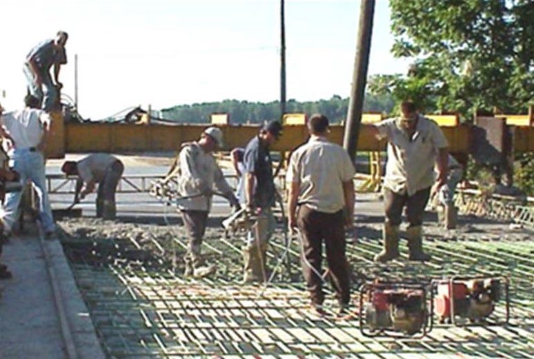
CONCRETE PLACEMENT .................................................................................................................................................... 6-7
Pre-Pour Conference .............................................................................................................................................. 6-7
Preparation of the Forms....................................................................................................................................... 6-8
Concrete Placement and Consolidation ................................................................................................................. 6-8
Finishing Operations .............................................................................................................................................. 6-9
Curing Requirements ........................................................................................................................................... 6-10
QC/QA SUPERSTRUCTURE CONCRETE .............................................................................................................................. 6-10
BRIDGE DECK REPAIR................................................................................................................... 7-1
PREPARATIONS FOR DECK REPAIR....................................................................................................................................... 7-1
HMA Widening ...................................................................................................................................................... 7-1
Traffic Control ........................................................................................................................................................ 7-2
SURFACE MILLING (OR SCARIFICATION) ............................................................................................................................... 7-3
Purpose .................................................................................................................................................................. 7-3
Equipment ............................................................................................................................................................. 7-4
Procedures ............................................................................................................................................................. 7-4
Measurement and Payment .................................................................................................................................. 7-5
LOCATING DETERIORATED AREAS OF DECK ........................................................................................................................... 7-5
Visual Inspection.................................................................................................................................................... 7-6
Sounding ................................................................................................................................................................ 7-6
Procedures For Marking ........................................................................................................................................ 7-6
REMOVING DETERIORATED AREAS OF DECK ......................................................................................................................... 7-7
Hand-chipping ....................................................................................................................................................... 7-7
Hydrodemolition .................................................................................................................................................... 7-7
REINFORCING BARS ......................................................................................................................................................... 7-8
PARTIAL-DEPTH AND FULL-DEPTH PATCHES ......................................................................................................................... 7-8
Resounding, Re-Inspecting, and Additional Removal ............................................................................................ 7-9
Cleaning ............................................................................................................................................................... 7-10
Measuring ........................................................................................................................................................... 7-10
Patching Procedure Using Bridge Floor Slab Patching Concrete ......................................................................... 7-10
EXPANSION JOINTS AND ROADWAY DRAINS ....................................................................................................................... 7-11
SS Joints (Expansion Joint SS)............................................................................................................................... 7-11
Modular Joints (Expansion Joint M) .................................................................................................................... 7-11
MATERIALS .................................................................................................................................................................. 7-12
Aggregates .......................................................................................................................................................... 7-12
Portland Cement.................................................................................................................................................. 7-12
   Latex Modifiers .................................................................................................................................................... 7-12
   Fly Ash ................................................................................................................................................................. 7-13
CALIBRATION................................................................................................................................................................ 7-13
   Equipment ........................................................................................................................................................... 7-13
   Pre-Calibration Inspection ................................................................................................................................... 7-13
   Initial Calibration ................................................................................................................................................. 7-13
PREPARATIONS AND FINAL INSPECTIONS PRIOR TO PLACING OVERLAY ..................................................................................... 7-15
   Blasting and Cleaning .......................................................................................................................................... 7-15
   Finishing Machine Set-Up .................................................................................................................................... 7-15
   Final Inspections of the Deck ............................................................................................................................... 7-16
OVERLAY PLACEMENT .................................................................................................................................................... 7-16
   Limitations ........................................................................................................................................................... 7-16
   Bond Coat ............................................................................................................................................................ 7-16
   Finishing .............................................................................................................................................................. 7-17
   Texturing ............................................................................................................................................................. 7-17
   Curing .................................................................................................................................................................. 7-18
POST-CURE INSPECTIONS, MEASUREMENT, AND PAYMENT ................................................................................................... 7-18
   Inspecting for Cracks ........................................................................................................................................... 7-18
   Sounding for Bond ............................................................................................................................................... 7-18
   Method of Measurement .................................................................................................................................... 7-19
   Basis of Payment ................................................................................................................................................. 7-19
PATCHING EXISTING OVERLAY ......................................................................................................................................... 7-19
BRIDGE CONSTRUCTION
OVERVIEW
TECHNICIAN DUTIES
   The general duties of a Bridge Technician are essentially the same as for all other
   Technicians. These duties are defined in Section 105.09 and are summarized here for easy
   reference.

   Bridge Technicians employed by INDOT are assigned to a contract to:
      1. Keep the Project Engineer or Project Supervisor (PEMS) informed of the progress
          of the work and the way the work is being done.
      2. Report whenever the materials furnished, or the work conducted, fails to fulfill the
          requirements of the Specifications and the contract.
      3. Call to the attention of the contractor any known deviation from, or infringement
          upon, the plans and Specifications with respect to materials and workmanship as they
          occur.

   Technicians are required to keep informed concerning the contractor's planned work for each
   day, including the location of the work, the work to be done, how much is done, and what
   equipment is used. The Technician is expected to complete the required daily reports and
   submit them promptly to the PEMS.

   Technicians are authorized to inspect all work conducted and materials furnished by the
   contractor. The Technician has the authority to reject defective materials and to suspend any
   work that is being done improperly subject to the final decision of the PEMS. Technicians
   may not change any requirement of the plans or Specifications, nor are they allowed to
   conduct other duties for the contractor.

BASIC BRIDGE TERMS
   An important first step in understanding the principles and processes of bridge construction
   is learning basic bridge terminology. Although bridges vary widely in material and design,
   there are many components that are common to all bridges. In general, these components
   may be classified either as parts of a bridge substructure or as parts of a bridge superstructure.

  SUBSTRUCTURE
   The substructure consists of all the parts that support the superstructure. The main
   components are abutments or end-bents, piers or interior bents, footings, and piling.

   Abutments support the ends of the bridge and confine the approach embankment, allowing
   the embankment to be built up to grade with the planned bridge deck. Integral and semi-
   integral end bents (abutments) are becoming more common. Typical abutment designs are
   illustrated in Figure 1-2.

                                              1-1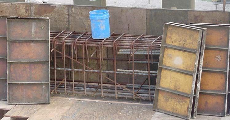
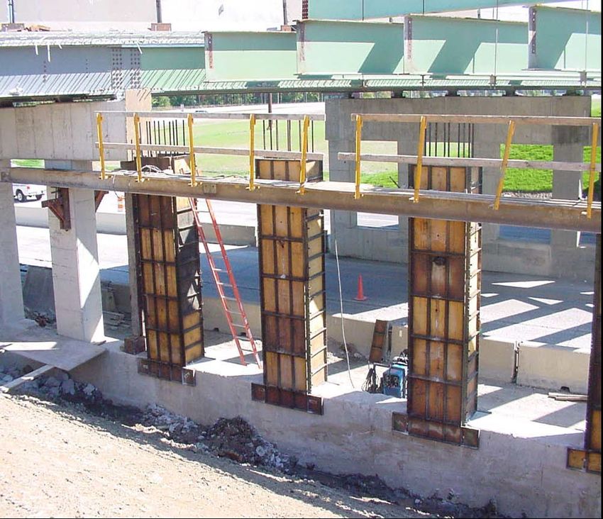
When a bridge is too long to be supported by
                                        abutments alone, piers or interior bents are built to
                                        provide intermediate support. Although the terms
                                        may be used interchangeably, a pier generally is
                                        built as a solid wall, while a bent is usually built
                                        with columns. Figure 1-1 illustrates several types of
                                        bents and piers.

    Figure 1-2 Abutments
The top part of abutments, piers, and
bents is called the cap. The structural
members rest on raised, pedestal-like
areas on top of the cap called bridge
seats. The part of abutments and bents
between the ends of the structural
members       and      the    approach                    Figure 1-1 Piers
embankment is called the mudwall. The
devices that are used to connect the structural members to the bridge seats are called shoes
or bearings.

                                        1-2
Abutments, bents, and piers are sometimes built on spread footings. Spread footings are large
blocks of reinforced concrete that provide a solid base for the substructure and anchor the
substructure against lateral movements.
Footings also serve to transmit loads
borne by the substructure to the
underlying foundation material.
When the soils beneath a footing are not
capable of supporting the weight of the
structure above the soil, bearing failure
occurs. The foundation shifts or sinks
under the load, causing structure
movement and damage (Figure 1-3).
Figure 1-3 Bearing Failure
1-3In areas where bearing failure or other
soil failure is likely, footings are built on
foundation piling (Figure 1-4). Piles are
load-bearing members that are driven
deep into the ground at footing locations
to stabilize the footing foundation. Piling
transmits loads from the substructure
units down to underlying layers of soil or
rock.
Figure 1-4 Structure Pilings
SUPERSTRUCTURE
The bridge superstructure consists of the components that span the obstacle the bridge
crosses and includes the following:
1. Bridge floor slab
2. Structural members
3. Bridge railings (parapets), handrails, sidewalk, lighting, and some drainage features.
A bridge floor is the entire length of the bridge from the roadway side of the mudwall or pile
cap to the other roadway side of the mudwall or pile cap and the entire width from one coping
edge across to the other coping edge. (The bridge deck is the roadway portion of a bridge,
including shoulders.) Most bridge floor slabs are constructed as reinforced concrete slabs,
but timber decks are occasionally used in rural areas and open-grid steel decks are used in
some movable bridge designs such as a bascule bridge. As polymers and fiber technologies
improve, Fiber Reinforced Polymer (FRP) decks may be used. Although technically not the
same thing, the terms bridge floor slab and bridge deck are often used interchangeably.
Bridge decks must match the grade of the approach roadway so that there is no bump or dip
as a vehicle crosses onto or off the bridge.
The most common causes of premature bridge deck failure are:
1. Improper amounts of air entraining admixtures, improper curing, a high
water/cementitious ratio, segregation of the concrete, or insufficient concrete
strength from an improper concrete mix design.
2. Improper concrete placement, such as failure to consolidate the mix as the concrete
is placed, pouring the concrete too slowly such that the concrete begins its initial set
prior to completing the pour, or not maintaining a placement rate in accordance with
the approved pour rate as per Section 704.04.
3. Insufficient concrete cover due to improper screed settings or incorrect installation
of the deck forms and/or reinforcement.
Consequently, it is the intent of INDOT, and therefore the Technician, to give particular
attention to these items so that bridge structures attain the longevity for which they are
designed.
1-4A bridge deck is usually supported by structural members. The most common types are:
1. Steel I-beams and girders
2. Precast, prestressed, reinforced concrete bulb T-beams
3. Precast, prestressed, reinforced concrete I-beams
4. Precast, prestressed, concrete box beams
5. Reinforced concrete slabs.
Secondary members called diaphragms are used as cross-braces between the main structural
members and are also part of the superstructure.
Bridge railings (parapets), handrails, sidewalks, lighting, and drainage features have little to
do with the structural strength of a bridge but are important aesthetic and safety items. The
materials and workmanship that go into the construction of these features require the same
level of inspection effort as any other phase of the work.
SPANS AND SPAN LENGTH
The terms bridge and span are used
interchangeably; however, to avoid
confusion and misunderstanding,
Technicians and construction personnel
draw a distinction between the two.
A bridge is made up of one or more spans.
A span is a segment of a bridge that
crosses from one substructure unit to the Figure 1-5 Bridge Spans
next, from abutment to abutment, from
abutment to pier, from pier to pier, or from pier to abutment.
Span length refers to either the length of any individual span within the structure or to the
total bridge length. In most cases, span lengths are considered as the distance between the
centerlines of bearing from one substructure unit to the next (Figure 1-5).
SIMPLE AND CONTINUOUS SPANS
In addition to the basic bridge design
(girder, arch, truss, suspension, etc.),
a bridge may be further classified as a
simple span, or a continuous span
(Figure 1-6). Both simple and
continuous spans may exist in the
same bridge. The classification is
based on the arrangement of the
bridge's structural members. Figure 1-6 Simple and Continuous Spans
A span with structural members that cross from one substructure unit to the next substructure
unit is a simple span. The simple span has fixed bearings on one end and expansion bearings
on the other end. Any bridge that is supported by abutments alone is a simple span. An
individual span within a bridge that extends from an abutment to a pier or a pier to another
1-5pier is also a simple span. Occasionally bridges are constructed as a series of simple spans,
although these are not common in Indiana.
A continuous span is a bridge or bridge segment with structural members that cross over one
or more substructure units without a break. The structural members may have to be spliced
to obtain the necessary length. Spliced structural members are still considered one-piece
members. Continuous spans are typically anchored to the substructure by expansion bearings
and a single fixed bearing.
BRIDGE PLANS
Bridge plans are generally attached as supplements to the roadway construction plans.
Although from time to time there will be stand-alone bridge projects. The basic types of
sheets in a set of bridge plans include the following.
TITLE AND INDEX SHEET
The title and index sheet identifies the bridge by contract number, unique structure number,
and location, and contains an index of all other sheets in the plans.
BORING DATA SHEETS
The boring data sheets indicate the results of soil borings made at the bridge site prior to
construction. The Technician uses these sheets to identify the types of soils that are
encountered during structure excavation, and to determine the approximate depths at which
the types of soils are found.
LAYOUT SHEET
The layout sheet consists primarily of a topographical situation plan of the bridge site and a
profile view of the proposed bridge grade.
The situation plan identifies the landowners and natural and manmade features in the
contract area. The plan also delineates right of way limits, limits of construction, and the
locations of benchmarks used for grade control. The layout sheet also may include a list of
utilities in the contract area that may be affected by the contract.
GENERAL PLAN SHEET
The General Plan sheet includes a plan view, which is the bridge seen from above, and an
elevation view, which is the bridge seen from the side.
The plan view identifies:
1. The exact location of the bridge in terms of the contract station numbers and the
obstacle the bridge is intended to cross
2. The degree of skew of the bridge
3. All important centerlines for the structure, roadway, and bearings
4. The overall length of the bridge and the lengths of all individual spans
5. All significant widths for the "out to outs," roadways, shoulders, sidewalks, and
bridge railings (parapets).
1-6The elevation view identifies:
1. Original and projected ground lines
2. Elevations of railroads, low water, high water, highways, etc., to be crossed and any
minimum vertical clearance requirements
3. Minimum tip elevation for piling, if used, and the planned bottom-of-footing
elevations
4. The locations of fixed and expansion bearings.
The General Notes section of the plans may be included on the General Plan sheet or may
be found on a separate sheet. Much of the information found in the General Notes is common
information that is essentially the same on all similar bridge contracts. There may also be
additional information that is contract specific in this section.
DETAIL PLAN SHEETS
Detail plan sheets provide details not included in the general plan and elevation views.
Typically, detail plan sheets are provided for each unit of the substructure, the framing plan
(superstructure details), and the floor details that describe how the bridge deck is to be built.
In many cases, identical or very similar bridge features are described on the same detail
sheet. For example, the plans for a bridge that has two nearly identical piers may include one
detail sheet to be used for both piers. Any significant difference between the two piers would
be noted on the plans. Detail sheets also include a bill of materials section. The bill of
materials lists the types and quantities of the materials that are required to construct that
particular part of the bridge according to the plans. The materials listed are primarily
concrete and reinforcing bars; however, miscellaneous items such as bearing pads, surface
seal, expansion joints, and roadway drains are typically noted as well.
BRIDGE SUMMARY AND ESTIMATE OF QUANTITIES SHEETS
The bridge summary sheet is a tabulation of the quantities of materials used in each part of
a bridge.
STANDARD DRAWINGS
Almost every bridge construction contract has features in common with bridges of similar
design, size, or location. Such items include railing details, pile splicing methods, details on
bearing assemblies, and many other items. Producing new drawings for these features each
time they are to be included on a contract would be time-consuming and repetitive. Instead,
plans for such items are included in the INDOT Standard Drawings.
CONTRACTOR PLANS OR DRAWINGS
In addition to the plans and drawings furnished by INDOT, working drawings may be
supplied by the contractor. Working drawings indicate the contractor's proposed methods of
meeting the requirements of the contract plans, the Special Provisions, and the Standard
Specifications. In all cases, contractor working drawings are required to be submitted and
approved by INDOT or its assigned designee. In the case of forming and falsework working
drawings, the contractor needs to have these drawings signed and stamped by a Professional
Engineer licensed in Indiana. INDOT personnel review these drawings.
1-7The following items require approval by INDOT:
1. Falsework and cofferdam working drawings
2. Working drawings for the fabrication and erection of structural members
3. Deck pour plans and sequence
4. Traffic control plan alternatives
5. Erosion control plan.
Any work conducted prior to the receipt of the approved working drawings is done at the
risk of the contractor. The contractor's drawings are approved for design features only.
Approval does not relieve the contractor from responsibility for errors or for the adequacy
and safety of the work (Section 105.02).
CONSTRUCTION CONTROLS AND LAYOUT
HORIZONTAL CONTROLS
To ensure the bridge lines up correctly with the approach roadways, the initial survey and
layout establishes one or more centerlines to guide the construction of the bridge. The
important lines for the Construction Engineering subcontractor to check include:
1. The centerline of construction (sometimes referred to as baseline of construction or
survey line)
2. The centerline of structure
3. The centerline of roadway
4. The centerline of bearing (may also be called centerline of pier, though they are not
necessarily the same thing).
Depending on the contract, the centerlines of construction, structure, and roadway may be
the same line or three different lines. For example, a two-lane bridge with no shoulders or
with shoulders of equal widths would probably have one line for all three references. In most
cases, however, one or more centerlines is different from the other centerlines.
Centerlines of bearing are transverse lines for the bridge seats or bearing areas on abutments
and piers (or bents) and intersect the longitudinal centerlines. Generally, if the centerlines of
bearing intersect the longitudinal centerlines at an oblique angle (an angle other than a right
angle), the bridge is said to be skewed or built on a skew. If the centerlines of bearing
intersect the longitudinal centerlines at right angles, there is no skew. Degrees of skew, if
any, are noted on the General Plan sheet and elsewhere on the plans.
VERTICAL CONTROLS
To maintain the proper grade of a bridge and the elevation of the various bridge components,
all construction is required to be referenced to benchmarks. Benchmarks are typically part
of a system of control points maintained by the US Geological Survey to guide all elevation
measurements and are used on bridge construction projects for functions such as structure
excavation, pile driving, and pouring the bridge deck.
Benchmarks for bridges are established during the bridge layout and their locations are
usually noted on the layout sheet. At least one benchmark on each side of the bridge is
1-8required to be checked for accuracy before construction begins. If a benchmark is on a
structure that is to be removed, a temporary benchmark is established and protected at a site
convenient to the new bridge. As soon as a footing, wingwall, or other permanent part of the
new structure is poured, the temporary benchmark is transferred to the new structure.
BRIDGE CONSTRUCTION LAYOUT
Bridge layout and staking is normally done by the contractor, or subcontractor, as
Construction Engineering. Layout involves establishing construction control points that are
used to maintain the horizontal and vertical alignment of the work that follows. After
performing the layout, the Surveyor furnishes the contractor with the information required
to complete the layout and to conduct the work. Technicians who have little, or no survey
work experience are encouraged to participate in the layout operation to acquaint themselves
with the locations of important construction control points and the methods used to establish
those points.
The first step in bridge layout is to locate previously established control points on each end
of the bridge site. The control points were established during the preliminary survey to
represent the baseline of construction or the survey line. This line is typically designated as
Line "A" on the plans, though other designations may be used.
Control points for the centerline of the structure and/or roadway must also be located if they
are different from the survey centerline. All points are checked for alignment and referenced
with offset stakes. The station of one of the control points is determined for use in locating
the abutments and piers.
The next step is to locate each unit of the substructure at points along the survey line.
Reference stakes for these points are set to the left and right of the centerline by turning the
skew angle. To ensure accuracy, the survey crew should double, and triple check the skew
angle. The accuracy of the skew angle may be checked by measuring the distance between
reference points on the left and right sides. If the distances between the points are equal on
both sides, the skew angle is correct.
Enough reference points are set to ensure easy replacement of the centerline control. The
reference points are protected and identified by guard stakes and flagging (plastic ribbons).
Once the reference points are set, the crew double-checks the elevations of the benchmarks.
Again, temporary benchmarks are required to be established when a benchmark on an
existing structure is to be replaced. If the bridge deck is to match an existing roadway, the
edges and centerline of the roadway are required to be profiled and checked against the
elevation of the new structure. This assures a smooth driving transition from the new
structure to the existing roadway.
The last step in the bridge layout is staking the footings and taking cross- sections of the
footing areas. The cross-sections are used to determine how much material the contractor is
required to remove during structure excavation.
1-9FOUNDATIONS
This chapter includes information on the inspection of bridge foundations. The two activities
most associated with the construction of bridge foundations are structure excavation and,
when necessary, pile driving. Both activities are conducted to construct a foundation of
adequate bearing that does not shift or sink under the loads that it supports. The soils at
natural ground level rarely have sufficient bearing capabilities to provide this support.
Through structure excavation, the unsuitable material at ground level is removed to expose
denser, more compact material below.
In some cases, the foundation material exposed through excavation has adequate bearing.
The footings for the bridge substructure units may be constructed and poured directly on the
floor of the excavation. In many locations, however, there is not material of sufficient
bearing for the footings. In those cases, foundation piling are driven to provide the necessary
support.
Section 206 outlines the requirements for structure excavation and Section701 describes the
requirements for piling.
STRUCTURE EXCAVATION
Unless otherwise specified,
structure excavation as a pay item
includes all associated activities
necessary to complete the work,
including providing drainage,
bracing, sheeting, and other
incidental items. Backfilling the
footings and disposing of unsuitable
material are also activities
commonly conducted and paid for
under the pay items for structure
excavation.
SOIL BORINGS
Before excavation for the footings
begins, INDOT personnel
investigate the underlying soils at
the footing locations through soil
borings. The soil borings indicate
the types of materials below the
surface and the elevations at which
they occur. Figure 2-1 Test Boring Log
The type of material at the footing locations determines, to a large degree, the bottom-of-
footing elevation and whether piling is required.
2-1The contract plans include a boring data sheet that illustrates where the borings were taken
in relation to the structure. In addition, a boring profile of each site indicates the types of
materials encountered and the elevations at which they occurred (Figure 2-1). Technicians
are required to note the type of material found at the planned bottom-of-footing elevation. If
the actual excavation contains material that differs greatly from what is shown in the profiles,
the excavation limits and the footing design may have to be revised. The bottom-of-footing
elevation on the profiles is required to be marked, if not already noted.
CROSS SECTIONS
Following the initial staking of the site, contract personnel (typically the Construction
Engineering subcontractor) are required to take cross-sections of the footing locations to
determine the volume of material that is required to be removed during the excavation
operation. Once the excavation is complete, additional cross-sections are taken to measure
the volume of material removed. Technicians are required to assure that enough cross-
sections are taken to ensure accuracy. The contractor is paid according to the volume of
material removed and the class of excavation required.
CLASSES OF STRUCTURE EXCAVATION
The class of excavation required is determined by the nature of the material to be removed
and the elevation at which the material is found. Sections 206.02-206.05 describe four
classes of excavation.
Class X Excavation
Class X excavation requires one or more of the following conditions:
1. The presence of solid rock, hard ledge rock, slate, hard shale, or conglomerate.
Because the material cannot be reasonably removed by any other method, blasting
or pneumatic or equivalent tools are required for removal.
2. The presence of loose stones or boulders that are more than 1/2 cu yd in volume.
3. The presence of concrete, masonry, or similar materials that are part of an old
structure that was not indicated on the plans.
4. The presence of timber grillages, old piling, buried logs, stumps, or other similar
materials that extend beyond the limits of excavation and are required to be cut off.
These materials are removed back to the cofferdam limits and paid as class X
excavation.
Hard pan is not considered as class X excavation. The limits of class X excavation are the neat
lines of the footer unless the excavation lies above another type of excavation (wet excavation,
for example) whose limits are different. In this case, class X excavation is paid to the limits of
the underlying material.
Wet Excavation
The plans usually indicate the upper limit of wet excavation with a horizontal line that
represents the water line. Wet excavation requires the removal of material from that line
down to the planned bottom-of-footing elevation. If the upper limit of wet excavation is not
shown on the plans, an elevation of one foot above the low water level indicated on the plans
is used instead.
2-2Wet excavation is measured and paid for in terms of the theoretical amount of material
bounded by the planned bottom-of-footing elevation, the upper limit of wet excavation, and
the vertical planes 18 in. outside of the neat lines of the footing dimensions indicated on the
plans.
Dry Excavation
Dry excavation involves removal of material above the upper limit of wet excavation.
Foundation Excavation (Unclassified)
Foundation excavation unclassified includes all required excavation that is not classified in
the proposal as either wet excavation or dry excavation. Foundation excavation does not
include class X excavation.
Structure excavation often includes a combination of these different classes. When there are
overlapping classes of excavation, each class is required to be measured and paid for
separately in conformance with the Specifications.
Except for wet excavation, all classes of structure excavation are measured and paid for
according to the number of cubic yards of material that is removed from the original position
and that is below the limits of roadway excavation.
LIMITS OF EXCAVATION
Structure excavation for footings is required to conform closely to the dimensions indicated
on the plans and allow enough room for the construction of any necessary forms, bracing, or
shoring. In most cases, the amount the contractor may be paid for is 18 in. outside the neat
lines of the planned dimensions. The contractor may remove more than that for their
convenience; however, in most cases this additional material is not paid for.
If the excavation material is material that is markedly different from what is shown on the
soil borings data sheet, the Technician is required to immediately notify the PEMS of the
discrepancy. The footing may require redesign. This is especially important as the
excavation gets closer to the planned bottom-of-footing elevation.
To guard against unexpected problems with a foundation, Section 206.11 contains
provisions to pay the contractor if lowering the footings is required. This section describes
the procedures to pay for the additional excavation for up to 4 ft below the planned bottom-
of-footing elevation. Excavation exceeding 4 ft below the planned bottom-of-footing
elevation is paid for as additional work. (Sections 104.03 and 109.05). Where a footing or a
portion of a footing is required deeper than the elevation indicated on the plans, such
additional excavation (except for class X) that is carried down to a plane which is 4 ft or less
below the bottom of footing or as indicated on the plans, is paid for as extended dry
excavation, extended wet excavation, or extended foundation excavation unclassified.
2-3You can also read