CAMINO PRO Installation Instructions Use and Care Information Instructions d'installation Utilisez et d'entretien Instrucciones de instalación ...
←
→
Page content transcription
If your browser does not render page correctly, please read the page content below
CAMINO PRO

Installation Instructions
Use and Care Information
Instructions d'installation
Utilisez et d'entretien
Instrucciones de instalación
Información de uso y cuidado

                CAPR36SS600
               CAPR36SS1200
               CAPR48SS1200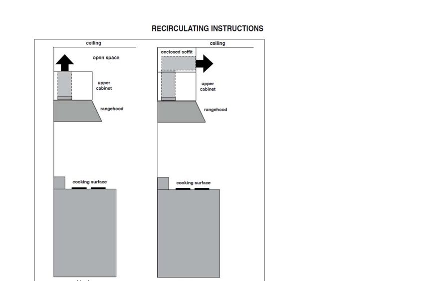
READ AND SAVE THESE INSTRUCTIONS BEFORE YOU START
            INSTALLING THIS RANGEHOOD
WARNING: - TO REDUCE THE RISK OF A RANGE TOP GREASE FIRE:
a) Never leave surface units unattended at high settings. Boilovers cause smoking and
   greasy spillovers that may ignite. Heat oils slowly on low or medium setting.
b) Always turn hood ON when cooking at high heat or when flambeing food (i.e. Crepes
   Suzette, Cherries Jubilee, Peppercorn Beef Flambé).
c) Clean ventilating fans frequently. Grease should not be allowed to accumulate on fan
   or filter.
d) Use proper pan size. Always use cookware appropriate for the size of the surface element.

WARNING: - TO REDUCE THE RISK OF INJURY TO PERSONS IN THE EVENT OF A
RANGE TOP GREASE FIRE, OBSERVE THE FOLLOWING*:
a) SMOTHER FLAMES with a close-fitting lid, cookie sheet, or metal tray, then turn off the burner.
    BE CAREFUL TO PREVENT BURNS.  If the flames do not go out immediately EVACUATE
    AND CALL THE FIRE DEPARTMENT.
b) NEVER PICK UP A FLAMING PAN - You may be burned.
c) DO NOT USE WATER, including wet dishcloths or towels - a violent steam explosion will
    result.
d) Use an extinguisher ONLY if:
    1. You know you have a Class ABC extinguisher, and you already know how to operate it.
    2. The fire is small and contained in the area where it started.
    3. The fire department is being called.
    4. You can fight the fire with your back to an exit.
* Based on "Kitchen Firesafety Tips" published by NFPA

WARNING - TO REDUCE THE RISK OF FIRE OR ELECTRIC SHOCK, do not use this
fan with any solid-state speed control device.

WARNING - TO REDUCE THE RISK OF FIRE, ELECTRICAL SHOCK, OR INJURY TO
PERSONS, OBSERVE THE FOLLOWING:
1. Use this unit only in the manner intended by the manufacturer. If you have any
    questions, contact the manufacturer.
2. Before servicing or cleaning unit, switch power off at service panel and lock the
    service disconnecting means to prevent power from being switched on acciden-
    tally. When the service disconnecting means cannot be locked, securely fasten a
    prominent warning device, such as a tag, to the service panel.
CAUTION: For General Ventilating Use Only. Do Not Use To Exhaust Hazardous or
Explosive Materials and Vapors.

WARNING - TO REDUCE THE RISK OF FIRE, ELECTRICAL SHOCK, OR INJURY TO
PERSONS, OBSERVE THE FOLLOWING:
1. Installation Work And Electrical Wiring Must Be Done By Qualified Person(s) In Accor-
   dance With All Applicable Codes And Standards, Including Fire-Rated Construction.
2. Sufficient air is needed for proper combustion and exhausting of gases through
   the flue (chimney) of fuel burning equipment to prevent backdrafting. Follow the
   heating equipment manufacturer's guideline and safety standards such as those
   published by the National Fire Protection Association (NFPA), and the American
   Society for Heating, Refrigeration and Air Conditioning Engineers (ASHRAE), and
   the local code authorities.
2
3.   When cutting or drilling into wall or ceiling, do not damage electrical wiring and
     other hidden utilities.
4.   Ducted fans must always be vented to the outdoors.
ALL WALL AND FLOOR OPENINGS WHERE THE RANGEHOOD IS INSTALLED MUST
                                          BE SEALED.
This rangehood requires at least 24" of clearance between the bottom of the rangehood
and the cooking surface or countertop. This hood has been approved by UL at this distance
from the cooktop.
This minimum clearance may be higher depending on local building codes. For gas cooktops
and combination ranges, a minimum of 30" is recommended and may be required.
Overhead cabinets on both sides of this unit must be a minimum of 18" above the cooking surface
or countertop. Consult the cooktop or range installation instructions given by the manufacturer
before making any cutouts.
MOBILE HOME INSTALLATION The installation of this rangehood must conform to the
Manufactured Home Construction and Safety Standards, Title 24 CFR, Part 3280 (formerly
Federal Standard for Mobile Home Construction and Safety, Title 24, HUD, Part 280). See
Electrical Requirements.
                                VENTING REQUIREMENTS
Determine which venting method is best for your application. Ductwork can extend either through the
wall or the roof.
The length of the ductwork and the number of elbows should be kept to a minimum to provide efficient
performance. The size of the ductwork should be uniform. Do not install two elbows together. Use
duct tape to seal all joints in the ductwork system. Use caulking to seal exterior wall or floor opening
around the cap.
Flexible ductwork is not recommended. Flexible ductwork creates back pressure and air turbulence
that greatly reduces performance.
Make sure there is proper clearance within the wall or floor for exhaust duct before making cutouts.
Do not cut a joist or stud unless absolutely necessary. If a joist or stud must be cut, then a supporting
frame must be constructed.
WARNING - To Reduce The Risk Of Fire, Use Only Metal Ductwork.
CAUTION - To reduce risk of fire and to properly exhaust air, be sure to duct air outside – Do
not vent exhaust air into spaces within walls or ceilings or into attics, crawl spaces, or garages.
Cold Weather installations
An additional back draft damper should be installed to minimize backward cold air flow and a nonmetallic thermal
break should be installed to minimize conduction of outside temperatures as part of the vent system. The damper
should be on the cold air side of the thermal break. The break should be as close as possible to where the vent
system enters the heated portion of the house.

         !                                WARNING
     • Venting system MUST terminate outside the home.
     • DO NOT terminate the ductwork in an attic or other enclosed space.
     • DO NOT use 4" laundry-type wall caps.
     • Flexible-type ductwork is not recommended.
     • DO NOT obstruct the flow of combustion and ventilation air.
     • Failure to follow venting requirements may result in a fire.
                                                                                                              3
ELECTRICAL REQUIREMENTS
A 120 volt, 60 Hz AC-only electrical supply is required on a separate 15 amp fused circuit. A time-delay
fuse or circuit breaker is recommended. The fuse must be sized per local codes in accordance with
the electrical rating of this unit as specified on the serial/rating plate located inside the unit near the field
wiring compartment.
! WARNING
• Electrical ground is required on this rangehood.
• If cold water pipe is interrupted by plastic, nonmetallic gaskets or other materials, DO
NOT use for grounding.
• DO NOT ground to a gas pipe.
• DO NOT have a fuse in the neutral or grounding circuit. A fuse in the neutral or
grounding circuit could result in electrical shock.
• Check with a qualified electrician if you are in doubt as to whether the rangehood is
properly grounded.
• Failure to follow electrical requirements may result in a fire.
State of California Proposition 65 Warning (US only)
WARNING
This product contains chemicals known to the State of California to cause cancer and birth
defects or other reproductive harm.
For more information go to www.P65Warnings.ca.gov
Note: The hood needs to be installed on a separate electrical circuit.
41 MOTOR - RANGEHOOD DIMENSIONS 36"
DRAFT 28-NOV-2018 17:
1 MOTOR RANGEHOOD REAR VENTING
52 MOTOR - RANGEHOOD DIMENSIONS 36"
DRAFT 28-NOV-2018 15:53
10" DUCT TRANSITION FOR 2 MOTOR RANGEHOOD 36"
9 13/16”
”
1/16
11
4 15/16”
11 7/1
6”
62 MOTOR - RANGEHOOD DIMENSIONS 48"
DRAFT 28-NOV-2018 16:20
10" DUCT TRANSITION FOR 2 MOTOR RANGEHOOD 48"
9 13/16”
”
1/16
11
4 15/16”
11 7/1
6”
7MAIN PARTS 1 MOTOR RANGEHOOD 36"
Components 12f 10
Ref. Qty. Product Components 9
1 1 Hood Body, complete with: Controls, Light
6 3 Grease filters
7 6 Filter knobs 1
8 1 Grease rail
9 1 Recirculation Vent Grill
10 1 Damper ø 5 7/8"
11 1 Blower 8
8
Ref. Qty. Installation Components
12a 2 Wall plug 7
12a 12b
12b 4 Screws 3/16"x1 15/16" 6
12c 6 Grease filters screws (3/16"x3/8")
12e 2 Motor fix screws (3/16"x 3/8")
12f 2 Screws 1/8"x 3/8" 9e
12c
(for Recirculation Vent Grill mounting)
11
Qty. Documentation 12e
1 Instruction Manual
8
8
MAIN PARTS 2 MOTOR RANGEHOOD 36"
Components 12f
Ref. Qty. Product Components 10 9
1 1 Hood Body, complete with: Con trols, Light
2 1 Duct transition 2 12d
6 3 Grease filters
7 6 Filter knobs
8 1 Grease rail 1
9 1 Recirculation Vent Grill
10 2 Damper ø 5 7/8"
11 2 Blower
8
Ref. Qty. Installation Components 8
12a 2 Wall plug
12b 4 Screws 3/16"x1 15/16"
7 12a 12b
12c 6 Grease filters screws (5/32"x5/16")
6
12d 4 screws 1/8"x1/4"
12e 4 Motor fix screws (3/16"x3/8")
12f 2 Screws 1/8"x 3/8"
9e
12c
(for Recirculation Vent Grill mounting)
Qty. Documentation 11
1 Instruction Manual 12e
8
88
8
8
MAIN PARTS 2 MOTOR RANGEHOOD 48"
8
Components 12f
Ref. Qty. Product Components 9
1 1 Hood Body, complete with: Controls, Light 10
2 1 Duct transition
6 4 Grease filters 2 12d
7 8 Filter knobs
8 1 Grease rail
9 1 Recirculation Vent Grill 1
10 2 Damper ø 5 7/8"
11 2 Blower
Ref. Qty. Installation Components 8
8
12a 2 Wall plug 8
12b 4 Screws 3/16"x1 15/16"
8
12c 8 Grease filters screws (5/32"x5/16") 7
7 12a 12b
12d 4 screws 1/8"x1/4" 6
6
12e 4 Motor fix screws (3/16"x 3/8") 7
12f 2 Screws 1/8"x 3/8" 6
(for Recirculation Vent Grill mounting) 9e
12c
9e
Qty. Documentation 9e
11
1 Instruction Manual
12e
8
7
6
9e
9PARTS NEEDED
6" Round Metal Ductwork
AVAILABLE ACCESSORIES
Telescopic Chimney Duct Cover:
- sku#: CHIM3448 (Use with 48" Camino Pro)
- sku#: CHIM2224 (Use with 36" Camino Pro)
- sku#: CHIM2248 (Use with 36" Camino Pro)
- sku#: CHIM3424 (Use with 48" Camino Pro)
CFM Reducer Accessory Kit sku#: CFMRED
CFM Reducer Accessory Kit sku#: CFMRED-2
Activated Charcoal Filter sku #: FILTER1
Charcoal Filter Kit Washable Long Lasting sku#: FILTER1LL
Min. 24" Min. 30"
101 MOTOR RANGEHOOD REAR INFORMATION
6"
Rear
1 MOTOR RANGEHOOD REAR DUCTED INSTALLATION
1
Only for the first installation
For a rear ducting installation
the blower bracket needs to be
unsecured by first removing the 12
screws as shown.
180°
Once the screws are removed,
extract it from the body of the Hood
and position it so the transition
opening is facing to the rear wall
(from the back remove and rotate
180 degrees to the left, and then flip
90° it back 90 degrees as shown in the
diagram).
Once the blower bracket is in place
reinstall the 12 screws to fasten the
bracket to the Hood body.
112 3
180°
90°
Put the motor in the hood body. Install the motor into the upper of the hood using
the 2 screws 12e supplied.
4
Connect the wire cable 9 hole end to the
motor.
9 hole end
121 MOTOR RANGEHOOD TOP DUCTED INSTALLATION
1 2
Put the motor in the hood body. Install the motor into the rear of the hood using
the 2 screws 12e supplied.
3
Connect the wire cable 9 hole end to the
motor.
9 hole end
13wiring, and test
FIGURE 15
2 MOTOR RANGEHOOD TOP DUCTED
3. Attach INSTALLATION
the blower bracket divider inside the hood, with the 2
screws into the top of the hood and 2 screws into the back, all
1 supplied with the blower kit (FIGURE 16)
FIGURE 19
FIGURE 16
4. Install the 2 motor kits into the sides of the blower bracket using
the 4 screws supplied with the motor kit. (FIGURE 17)
5. Connect the wire (FIGURE 18) that comes with the motor kit
Put the 2 motors in the hood body. Inside thefrom
hood there
the side of theistwo
a motors
blower bracket
to the divider
connection and the
on the inside
of the light panel in the hood. The two - 9 hole ends of the wire
motors will be one a side. are installed in the two motors, the 6 hole end is connected to FIGURE 20
the light panel (FIGURE 11 on the previous page)
2
ATION WITH IB1200 INTERNAL BLOWER (1200 cfm)
he Plate B (FIGURE 14) which came with the internal
on top of the rangehood with the holes located closer to
Use 9 screws supplied with the blower kit
B
Install the 2 motors into the sides of the blower bracket using
FIGURE 17 the 4 screws 12e supplied.
3
E 14
e the white plastic covering and Install the 4 side trim
he outside of the hood using (16) part 9b screws, see
il installation in (FIGURE 15). 9 hole end
FIGURE 18 9 hole end
6. Install the 2 dampers on top of the hood. If you want one 10"
round duct to come out of the top of the hood, use the transition
9 hole end piece (FIGURE 19) that comes with the motor kit and install with
four screws. If you want to use 2 seperate 6" round ducts, do not
use theConnect
transition.the wire cable 9 hole end to the
left motor and the other wire cable 9 hole
7. Attach
end thetohood to the
the right cabinet using (12) 9c. screws to the
motor.
cabinet. FIGURE 20
8. Follow steps 6 - 9 on the previous page to connect ducting,
14
wiring, and test the electrical connection.H
HHINSTRUCTIONS
INSTALLATION
Install Damper that is included with the
Hood before connecting to the ductwork.
One for 1 motor model.
Two for 2 motor model.
Installation Instruction for Mounting on the Wall
1 I
I I
= =
Min. 24" Min. 30"
Draw a vertical line on the supporting wall as high as practical, at the center of the area in which
the hood will be installed.
Draw a horizontal line at where the bottom edge of the hood will be located as indicated in the
figure that is a minimum of 24" or 30" above cooking surface.
152.a Installation for 1 Motor Rangehood
L = 19 11/16”
L
16 1/2”
x2
Ø 1/2”
x2
24”
30”
36”
Mark the wall where indicated, 16 1/2" above the horizontal line and at L distance on the left and right
of vertical line. The distance L changes for all dimension of Hood.
Insert the two wall plugs 12a in the holes as shown and fix them.
L
16 1/2”
x2
Ø 1/2”
x2
24”
30”
36” 48”
L = 19 11/16” L = 31 1/8”
For a different type of Wall, it's
possible to use only the bracket by
remove the plug and the screw from
the plug 12a. 36” - 48”
Combine the bracket with specific
wall plug or screw.
162.b Installation for 2 Motor Rangehood
L
16 1/2”
x2
Ø 1/2”
x2
24”
30”
36” 48”
L = 19 11/16” L = 31 1/8”
36” - 48”
Mark the wall where indicated, 16 1/2" above the horizontal line and at L distance on the left and right
of vertical line. The distance L changes for all dimension of Hood.
Insert the two wall plugs 12a in the holes as shown and fix them.
For a different type of Wall, it's
possible to use only the bracket by
remove the plug and the screw from
the plug 12a.
Combine the bracket with specific
wall plug or screw.
173 4
11b
Hook the hood body onto the wall plugs 12a. Use a level to insure that Fixing Bracket is level
by adjusting the screws as shown in the picture.
5
Mark the wall where indicated.
x4
Ø 5/16” Drill directly into ø 5/16" holes at all the center points marked.
x4
Insert the purchased wall plugs in the holes.
x4
Using thhe remaining screws to anchor the hood in holes.
If installation uses the telescopic chimney extension, refer to the installation manual included in
the Chimney Kit (CHIM3448 - CHIM2224 - CHIM2248 - CHIM3424)
181 AND 2 MOTORS STANDARD DUCTING METHODS
Vertical
Horizontal
Rear
(Valid for 1
motor range-
hood only)
1 AND 2 MOTORS DUCTING METHODS 6"
Install Roof or Wall Cap purchased separately. Connect the 6" metal ductwork to the Roof or Wall Cap and
then attach ductwork.
192 MOTORS DUCTING METHODS 10"
Fix the Duct transition in the hood body with
4 screws 12d.
Install Roof or Wall Cap purchased separately. Connect the 10" metal ductwork to the Roof or Wall Cap
and then attach ductwork.
20Non Ducted - Recirculation Option
12f
9
´
For Non-Ducted Recirculation venting route the ductwork to a location above the hood
where the discharge is vented back into the room.
Use the included Recirculation Vent Grill (9) to cover the opening. Secure the grill with the
2 screws (12f) provided in the Install Kit.
If the directional grille is not used, fit a straight tube at least 15" in length from the hood air
outlet to the wall unit.
Required Activated Charcoal Filter
Accessory - sku #: FILTER1
Long Lasting Activated Charcoal Filter
Accessory - sku #: FILTER1LL
(purchased separately)
21RECIRCULATION INSTRUCTIONS
enclosed soffit
open space
This page needs to be inserted
upper upper after Page This
9 andpage needs
before to10
Page be inserted
cabinet cabinet
after Page 9 and before Page 10
rangehood rangehood
cooking surface cooking surface
Note: recommended for 600 CFM
version only
Note: It is recommended that pro
fessional style cooking always be
vented to the outside; for recirculat
ing installations, some duct work is
required to exhaust the unit out of
the cabinet.
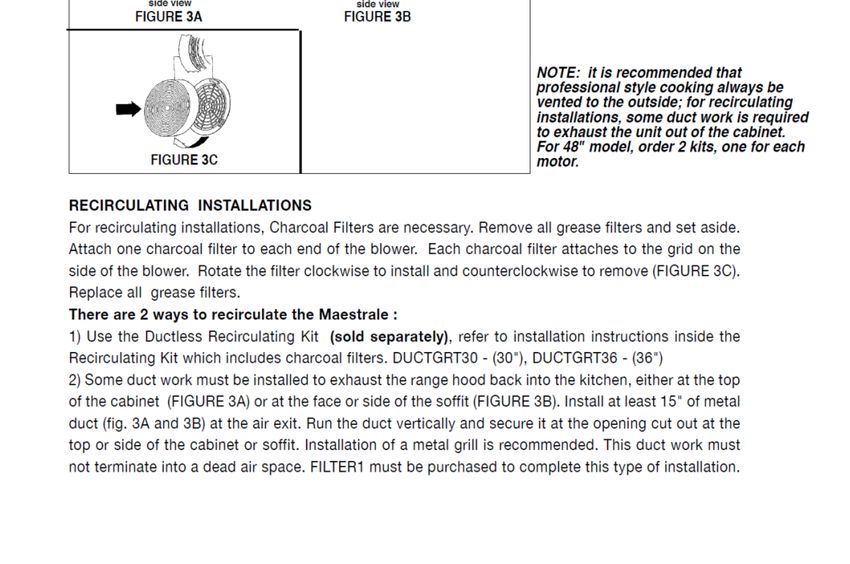
RECIRCULATING INSTALLATIONS
For recirculating installations, Charcoal Filters are necessary. Remove all grease filters
and set aside. Attach one charcoal filter to each end of the blower. Each charcoal filter
attaches to the grid on the side of the blower. Rotate the filter clockwise toAdd the and
install new
kit Add the new
counterclockwise to remove (FIGURE 3C). Replace all grease filters. kit
:DUCTGRT42
–(42“) :DUCTGRT42
Some duct work must be installed to exhaust the rangehood back into the kitchen, either
–(42“)
at the top of the cabinet (FIGURE 3A) or at the face or side of the soffit (FIGURE 3B).
Install at least 15" of metal duct (fig.3A and 3B) at the air exit. Run the duct vertically and
secure it at the opening cut out at the top or side of the cabinet or soffit. Installation
Required Activated Charcoal Filter Accessory - sku
# - FILTER1
Long Lasting Activated Charcoal Filter Accessory -
sku # FILTER1LL
(purchased separately)
226
Hook the Grease rail (8) positioning it inside
the hood. It is possible to wash and reposition
the rail inside the hood.
8
7
Installation of wiring connection
Switch off the dedicated power supply to the
hood.
Remove the wiring electrical knockout using a
flat-blade screwdriver. Feed the Power Supply
Cable through the electrical knockout.
Connect the Power Supply Cable to the ran-
gehood. Attach the White lead of the power
supply (A) to the White lead of the rangehood
(D) with a twist-on type wire connector. Attach
the Black lead of the power supply to the Black
lead of the rangehood (B) with a twist-on type
wire connector (C). Connect the Green (E)
(Green and Yellow) ground wire under the
Green grounding screw.
Replace the field wiring compartment cover
and the grease filters.
Connect the ductwork to the damper and seal
all connections with duct tape.
Turn the power supply on. Turn on the blower
and light. If the rangehood does not operate,
check that the circuit breaker is not tripped
or the house fuse blown. If the unit still does Hood wiring
not operate, disconnect the power supply and
check that the wiring connections have been
made properly.
Reattach the field wiring compartment cover.
238
9e
12c
9e
12c
6
1
7
7
2
Before installing the filters (6), tighten the 2 knobs (7) with 2 screws (12c).
Use two hands to insert and remove the filters.
The 36" hood has 3 Filters.
The 48" hood has 4 Filters.
INSTALLATION CONTINUED
Optional Telescopic Chimney Extension Installation
Refer to Instructions inthe Chimney Duct Ccover Accessories.
24USE AND CARE INFORMATION
Rangehood Control Panel
The control panel is located in the center of the hood bottom.
Warning: Do NOT force the control dial to turn beyond its limit.
B0 B1
B2
Function Operation LED Color / Light Pattern
Lights - Dimmer Press the button once to turn the lights on dimmer (B2)
Lights - High Press the button a second time to turn the lights on high (B2)
Lights - Off Press the button a third time to turn the lights off (B2)
Speed 1 Quick turn of the knob to the right (1st time) (B1) Green - Solid
Speed 2 Quick turn of the knob to the right (2nd time) (B1) Yellow - Solid
Speed 3 Quick turn of the knob to the right (3rd time) (B1) Red - Solid
Intensive Speed (motor
turns off after 10 Quick turn of the knob to the right (4th time) (B1) Red - Blinking
minutes of operation)
While at any speed, hold the knob for 2 seconds to the left to
turn the motor off. Alternatively, a quick turn of the knob to the
Turn the motor off No Color
left backwards thru the speeds (1 turn to the left past speed
1) , turns the motor off. (B0)
Hold the knob to the right for 2 seconds. The hood and lights
Delay auto shut off The selected speed blinks
stay on for 10 minutes, then turn off. (B1)
Heat Sensor Active Press button for 2 seconds (B2) Red Blinking One time
Heat Sensor Inactive Press button for 2 seconds (B2) Red Blinking Three times
Heat Sensor Fault Purple blinking
If the motor is off and the temperature gets to approximately
130 degrees F (55 degrees C°)– the blower turns on speed
2 for a minimum of 15 minutes. Once the temperature has
Heat Sensor Features Red - Blinking
dropped below 130 degrees F (55 degrees C°), the motor
turns off. If you operate the hood manually during this
function, the auto on sensor is disabled for 15 minutes.
If the temperature remains too high, the blower remains on
Heat Sensor Faults for up to 90 minutes until the temperature has dropped below Red - Blinking
130 degrees F (55 degrees C°).
25Cleaning metal grease filters
The metal grease filters can be cleaned in hot detergent
solution or washed in the dishwasher. They should be
cleaned every 2 months, or more frequently if use is
particularly heavy.
• Install the grease rail into the back of the hood, into
the slots on the inside floor of the rear of the hood
• Thegreasefiltersshouldbeinstalledbeforeoperating
the rangehood. 1
• To install the filters, use the two knobs to hold the filter
and insert the filter into the front edge of the hood
with the knobs facing out into the spring loaded slot.
Install the other end of the filter above the grease rail
2
in the back of the hood.
• No water can be present in filters before installing
back in hood.
Replacing Activated Charcoal Filter
The Activated Charcoal Filters are not washable
and cannot be regenerated, and should be replaced
approximately every 4 months of operation, or more
frequently with heavy usage.
• Remove the charcoal filter by rotating it clockwise (
backwards) until it unlocks from the motor housing and
pull off sideways.
• To re-insert each charcoal filter, place up against
the side of the blower and push it inward. Then
turn the charcoal filter clockwise (forward) until it
fits into place.
Caution: "When used in recirculation mode, to
Reduce the Risk of Fire and Shock use only conver-
sion kit Model FILTER 1 or FILTER1LL".
Lighting unit
• Remove the snap-on lamp cover
by levering it from under the metal Gu10 self-ballasted led
ring, supporting it with one hand. lamps – listed in ac-
• Replace the lamp with a new one cordance with
of the same type, making sure that ul 1993/nmx-
you insert the two pins properly into j-578/1-ance/
the housings on the lamp holder. csa c22.2 No.
• Replace the snap-on lamp cover. 1993
269
8
7 Wiring Diagram
LED
LED
FLAT CABLE
LED
6
LED
line filter
LUX1
Faber ATF
1
ORG(vlt)
2
ORG(red)
FLAT CABLE
1
AUX
5
2
Y-G
120Vac 60Hz
LUX2
BLK
1
LINE
2
WHT
Y-G
1
BRW
2
L-B
MOTOR
WIRING
BOX
3
PNK
4
4
BLU
5
WHT
6
GRY
7
BLK
ORG (YELL)
BRW
BLU
M1 M8-4V
YEL
BLK
WHT
3
RED
GRY
BLK
ORG (YELL)
BRW
BLU
M1 M8-4V
WHT
RED
2
GRY
BLK
SENSOR
1
Code 991.0573.191
Created by DOLCE CORRADO
Creation date 19.Dic.2018
Denomination Doc Type
WIRING DIAGRAM M8-4V ATF SENSOR GU10 LED Approved by Dolce, Corrado
Modification description Approved date
19-Dec-2018
Doc.status Released
0
27
These drawings and specifications are the property of Franke Technology and
Trademartk Ltd and shall not be reproduced.copied or trasferred to any third party Modif. by
without the prior written permission of Franke Tecnology and Trandemark Ltd.
Switzerland.It is strictly prohibited to get quotes from the drawing or bring
modifications without the prior written conset of franke Techology and Trademark
Drawing N :
H90_559 Rev : 01FABER CONSUMER WARRANTY & SERVICE
All Faber products are warranted against any defect in materials or workmanship for the original purchaser
for a period of 1 year from the date of original purchase (requires proof of purchase). This warranty covers
labor and replacement parts. Faber, at its option, may repair or replace the product or components
necessary to restore the product to good working condition. To obtain warranty service, contact the dealer
from whom you purchased the range hood, or the local Faber distributor. If you cannot identify a local Faber
distributor, contact us at (508) 358-5353 for the name of a distributor in your area.
The following is not covered by Faber's warranty:
1. Service calls to correct the installation of your range hood, to instruct you how to use your range hood, to
replace or repair house fuses or to correct house wiring or plumbing.
2. Service calls to repair or replace range hood light bulbs, fuses or filters. Those consumable parts are
excluded from warranty coverage.
3. Repairs when your range hood is used for other than normal, single-family household use.
4. Damage resulting from accident, alteration, misuse, abuse, fire, flood, acts of God, improper installation,
installation not in accordance with electrical or plumbing codes or Faber documentation, or use of products
not approved by Faber.
5. Replacement parts or repair labor costs for units operated outside the United States or Canada, including
any non-UL or C-UL approved Faber range hoods.
6. Repairs to the hood resulting from unauthorized modifications made to the range hood.
7. Expenses for travel and transportation for product service in remote locations and pickup and delivery
charges. Faber range hoods should be serviced in the home.
THIS WARRANTY DOES NOT ALLOW RECOVERY OF INCIDENTAL OR CONSEQUENTIAL DAMAGES, INCLUDING, WITHOUT
LIMITATION, DIRECT, INDIRECT, INCIDENTAL, SPECIAL OR CONSEQUENTIAL DAMAGES, PERSONAL INJURY/WRONGFUL
DEATH OR LOST PROFITS FABER WARRANTY IS LIMITED TO THE ABOVE CONDITIONS AND TO THE WARRANTY PERIOD
SPECIFIED HEREIN AND IS EXCLUSIVE. EXCEPT AS EXPRESSLY SPECIFIED IN THIS AGREEMENT, FABER DISCLAIMS ALL
EXPRESS OR IMPLIED CONDITIONS, REPRESENTATIONS, AND WARRANTIES INCLUDING, WITHOUT LIMITATION, ANY
IMPLIED WARRANTIES OF MERCHANTABILITY OR FITNESS FOR A PARTICULAR PURPOSE.
This warranty gives you specific legal rights that may vary from state to state.
Model#: ______________________________ Serial #: _____________________________
January 4, 2016
28VEUILLEZ LIRE ET CONSERVER LA PRÉSENTE NOTICE AVANT DE
COMMENCER L'INSTALLATION DE LA HOTTE DE CUISINE
AVERTISSEMENT:-POUR RÉDUIRE LE RISQUE D'UN FEU DE GRAISSE SUR LA TABLE DE
CUISSON :
a) Ne laissez jamais sans surveillance les éléments de la surface de cuisson à température élevée.
Les bouillonnements excessifs peuvent provoquer de la fumée et les débordements de graisse
peuvent s'enflammer. L'huile doit être chauffée lentement, à une température basse ou moyenne.
b) Assurez-vous de toujours mettre en marche le ventilateur de la hotte lorsque vous cuisinez
à température élevée ou préparez un mets flambé (p.ex. crêpes Suzette, cerises jubilé, bœuf
flambé).
c) Nettoyez régulièrement les ventilateurs d'aspiration. Assurez-vous de ne pas laisser de la graisse
s'accumuler sur le ventilateur ou le filtre.
d) Utilisez toujours des poêles et casseroles de la taille appropriée. Utilisez toujours des ustensiles
de cuisine de la taille adaptée à celle de l'élément chauffant.
AVERTISSEMENT : - POUR PRÉVENIR LES BLESSURES EN CAS DE FEU DE GRAISSE SUR LA
TABLE DE CUISSON, SUIVEZ LES RECOMMANDATIONS SUIVANTES* :
a) ÉTOUFFEZ LES FLAMMES à l'aide d'un couvercle hermétique, d'une plaque à biscuits ou d'un
plateau métallique, puis éteignez le brûleur. FAITES ATTENTION AUX BRÛLURES. Si le feu ne
s'éteint pas immédiatement, QUITTEZ LES LIEUX ET APPELEZ LES POMPIERS.
b) NE PRENEZ JAMAIS UNE CASSEROLE EN FLAMME - Vous pourriez vous brûler.
c) N'UTILISEZ JAMAIS DE L'EAU, ni un linge à vaisselle ou un torchon mouillé, pour éteindre le feu.
Cela pourrait provoquer une violente explosion de vapeur.
d) Utilisez un extincteur UNIQUEMENT si :
1. Vous êtes certain qu'il s'agit d'un extincteur de classe ABC et que vous connaissez bien son
mode d'emploi.
2. Le feu est de faible intensité et se limite à l'endroit où il a démarré.
3. Les pompiers ont déjà été appelés.
4. Une voie de sortie se trouve derrière vous pendant que vous éteignez les flammes
* D'après le guide « Kitchen Firesafety Tips » publié par la NFPA aux États-Unis
AVERTISSEMENT-POURRÉDUIRELERISQUED'INCENDIEOUDECHOCÉLECTRIQUE,n'utilisez
jamais ce ventilateur en association avec un dispositif de réglage de vitesse à semi-conducteurs.
AVERTISSEMENT - POUR RÉDUIRE LES RISQUES D'INCENDIE, DE CHOC ÉLECTRIQUE OU DE
BLESSURE CORPORELLE, RESPECTEZ LES INSTRUCTIONS SUIVANTES :
1. Utilisez cet appareil uniquement de la façon prévue par le fabricant. Pour toute question, com-
muniquez avec le fabricant.
2. Avant de procéder à l'entretien ou au nettoyage de l'appareil, coupez l'alimentation au niveau du
panneau électrique et verrouillez-le pour vous assurer que l'électricité n'est pas rétablie accidentel-
lement. S'il n'est pas possible de verrouiller le dispositif d'interruption de l'alimentation, affichez de
façon ferme et bien visible un avis de danger, par exemple à l'aide d'une étiquette sur le panneau.
ATTENTION : Destiné à un usage de ventilation générale uniquement. N'utilisez pas ce dispositif
pour l'aspiration de vapeurs ou de matériaux dangereux ou explosifs.
AVERTISSEMENT - POUR RÉDUIRE LES RISQUES D'INCENDIE, DE CHOC ÉLECTRIQUE OU DE
BLESSURE CORPORELLE, RESPECTEZ LES INSTRUCTIONS SUIVANTES :
1. L'installation et le branchement électrique doivent être réalisés par un technicien qualifié et
conformément à tous les codes et normes en vigueur, incluant ceux concernant la construction
à l'épreuve du feu.
2. Afin de garantir une combustion et une évacuation adéquates des gaz par les conduites de la
cheminée des appareils à combustion, une bonne aération est nécessaire pour éviter le refou-
lement. Respectez les lignes directrices fournies par le fabricant du matériel chauffant, ainsi que
les normes de sécurité comme celles publiées par la National Fire Protection Association (NFPA)
et la American Society for Heating, Refrigeration and Air Conditioning Engineers (ASHRAE) aux
États-Unis, ainsi que les codes en vigueur dans votre région.
293. Lorsque vous faites une ouverture ou percez dans un mur ou le plafond, veillez à ne pas en-
dommager les fils électriques ou d'autres dispositifs cachés.
4. Les ventilateurs canalisés doivent toujours être raccordés à l'extérieur.
TOUTE OUVERTURE DANS LE MUR OU LE PLANCHER À PROXIMITÉ DE LA
HOTTE DOIT ÊTRE SCELLÉE.
Un espace libre d'au moins 24" est requis entre le bas de la hotte et la surface de cuisson
ou le comptoir. Cette hotte a été homologuée par l'UL à cette distance de la surface de cuisson.
L’espace libre minimal requis peut-être plus grand, selon la réglementation en matière de
construction de votre région. Pour les cuisinières à gaz et les cuisinières combinées, un
espace minimal de 30" est recommandé et pourrait être exigé.
Les armoires suspendues de chaque côté de l'appareil doivent se trouver à au moins 18"
de la surface de cuisson ou du comptoir. Consultez la notice d'installation de la surface de
cuisson ou de la cuisinière fournie par le fabricant avant de pratiquer des ouvertures.
INSTALLATION DANS UNE MAISON MOBILE L'installation de cette hotte doit être conforme
à la Partie 3280 de la norme Manufactured Home Construction and Safety Standards, Title 24
CFR (précédemment la partie 280 de la norme Federal Standard for Mobile Home Construction
and Safety, Title 24, HUD). Consultez la fiche technique électrique.
CRITÈRES DE VENTILATION
Déterminez quelle méthode de ventilation est mieux adaptée à votre application. Les conduits peuvent
passer par le mur ou le toit.
Pour garantir une meilleure efficacité, la longueur des conduits et le nombre de coudes doivent être le plus
limités que possible. Le diamètre des conduits devrait être uniforme. N'installez pas deux coudes ensemble.
Utilisez un ruban pour canalisations afin de sceller tous les joints du système de conduits. Utilisez un calfeu-
trage pour sceller les ouvertures dans le mur extérieur ou le plancher, autour du clapet.
Iln'estpasrecommandéd'utiliserdesconduitsflexibles. Lesconduitsflexiblesprovoquentunecontre-pression
et de la turbulence qui diminuent grandement l'efficacité de l'appareil.
Assurez-vous que l'espace libre dans le mur ou le plancher est suffisant pour le conduit d'évacuation avant de
pratiquer les ouvertures. Ne coupez jamais une poutre ou un chevron, sauf si c'est absolument nécessaire.
S'il s'avère nécessaire de couper une poutre ou un chevron, la construction d'un renforcement est requise.
AVERTISSEMENT - Pour réduire le risque d'incendie, utilisez uniquement des conduits métalliques.
ATTENTION - Pour réduire le risque d'incendie et pour évacuer adéquatement l'air, assurez-vous
de raccorder les conduits à l'extérieur – Ne diffusez pas l'air d'évacuation dans des espaces à
l'intérieur des murs ou du plafond, ou encore à l'intérieur d'un grenier, d'une galerie technique
ou d'un garage.
Installation dans les climats froids
Le système de ventilation doit prévoir un registre antirefoulement supplémentaire pour réduire le flux d'air froid inverse,
ainsi qu'une barrière thermique non métallique pour réduire la conduction des températures extérieures. Le registre
doit être installé du côté air froid par rapport à la barrière thermique. La barrière thermique doit être positionnée le plus
près que possible de l'endroit où le système de ventilation pénètre dans la partie chauffée de la maison.
! AVERTISSEMENT
• Le système de ventilation DOIT déboucher à l'extérieur.
• NE FAITES PAS déboucher les conduits dans un grenier ou un autre endroit fermé.
• N'UTILISEZ PAS un clapet de sécheuse mural de 4 po.
• Il n'est pas recommandé d'utiliser des conduits flexibles.
• N'ENTRAVEZ PAS le flux de l'air de combustion et de ventilation.
• Le non-respect des exigences en matière de ventilation pourrait entraîner un incendie.
30FICHE TECHNIQUE ÉLECTRIQUE
Une alimentation de courant alternatif de 120 volts à 60 Hz est requise sur un circuit à fusible distinct de
15 ampères. Il est recommandé d'installer un fusible temporisé ou un disjoncteur. Le fusible doit être
calibré conformément aux codes en vigueur pour les caractéristiques nominales électriques de l'appareil,
indiquées sur la plaque signalétique située à l'intérieur de l'appareil, à proximité du compartiment des
câblages externes.
! AVERTISSEMENT
• Une mise à la terre électrique est requise pour cette hotte.
• N'UTILISEZ PAS un tuyau d'eau froide pour la mise à la terre si celui-ci est branché par des
joints en plastique, par des rondelles non métalliques ou d'autres matériaux.
• N'UTILISEZ PAS une conduite de gaz pour la mise à la terre.
• N'INSTALLEZ PAS un fusible sur le circuit neutre ou le circuit de mise à la terre. La présence
d'un fusible dans le circuit neutre ou de mise à la terre peut entraîner un choc électrique.
• Consultez un électricien qualifié si vous n'êtes pas certain de la mise à la terre de la hotte.
• Le non-respect des exigences de la fiche technique électrique pourrait entraîner un incendie.
Avertissement de la proposition 65 de l'État de Californie (US seulement)
ATTENTION
Ce produit contient des produits chimiques connus de l'État de Californie pour causer le
cancer et des malformations congénitales ou d'autres problèmes de reproduction.
Pour plus d'informations, visitez www.P65Warnings.ca.gov
Remarque : La hotte doit être installée sur un circuit électrique séparé.
311 MOTEUR - DIMENSIONS DE LA HOTTE 36"
DRAFT 28-NOV-2018 17:
1 MOTEUR - VENTILATION ARRIÈRE DE LA HOTTE
322 MOTEURS - DIMENSIONS DE LA HOTTE 36"
DRAFT 28-NOV-2018 15:53
PIÈCE DE TRANSITION DU CONDUIT 10" POUR HOTTE 2 MOTEURS 36"
9 13/16”
”
1/16
11
4 15/16”
11 7/1
6”
332 MOTEURS - DIMENSIONS DE LA HOTTE 48"
DRAFT 28-NOV-2018 16:20
PIÈCE DE TRANSITION DU CONDUIT 10" POUR HOTTE 2 MOTEURS 48"
9 13/16”
”
1/16
11
4 15/16”
11 7/1
6”
34PIÈCES PRINCIPALES - HOTTE 1 MOTEUR 36’’
Composants 12f 10
Réf. Qté Composants du produit 9
1 1 Bâti de la hotte, avec : Interrupteurs, éclairage
6 3 Filtres à graisse
7 6 Boutons des filtres 1
8 1 Gouttière
9 1 Grille d’évent de recyclage
10 1 Registre ø 5 7/8"
11 1 Ventilateur 8
8
Réf. Qté Composants d’installation
12a 2 Chevilles 7
12a 12b
12b 4 Vis 3/16" x1 15/16" 6
12c 6 Vis des filtres à graisse (3/16"x3/8")
12e 2 Vis de fixation de moteur (3/16" x 3/8")
12f 2 Vis 1/8"x 3/8" (pour le montage de la grille 9e
12c
d’évent de recyclage)
11
Qté Documentation 12e
1 Mode d’emploi
8
8
PIÈCES PRINCIPALES - HOTTE 2 MOTEURS 36’’
Composants 12f
Réf. Qté Composants du produit 10 9
1 1 Bâti de la hotte, avec : Interrupteurs, éclairage
2 1 Pièce de transition du conduit 2 12d
6 3 Filtres à graisse
7 6 Boutons de filtre
8 1 Gouttière 1
9 1 Grille d’évent de recyclage
10 2 Registres ø 5 7/8"
11 2 Ventilateurs
8
Réf. Qté Composants d’installation 8
12a 2 Chevilles
12b 4 Vis 3/16"x1 15/16"
7 12a 12b
12c 6 Vis de filtres à graisse (5/32" x 5/16")
6
12d 4 Vis 1/8" x 1/4"
12e 4 Vis de fixation de moteur (3/16" x 3/8")
12f 2 Vis 1/8"x 3/8" (pour le montage de la grille
9e
12c
d’évent de recyclage)
Qté Documentation 11
1 Mode d’emploi 12e
35
88
8
8
PIÈCES PRINCIPALES - HOTTE 2 MOTEURS 48’’
8
Composants 12f
Réf. Qté Composants du produit 9
1 1 Bâti de la hotte, avec : Interrupteurs, éclairage 10
2 1 Pièce de transition du conduit
6 4 Filtres à graisse 2 12d
7 8 Boutons de filtre
8 1 Gouttière
9 1 Grille d’évent de recyclage 1
10 2 Registres ø 5 7/8"
11 2 Ventilateurs
Réf. Qté Composants d’installation 8
8
12a 2 Chevilles 8
12b 4 Vis 3/16"x1 15/16"
8
12c 8 Vis des filtres à graisse (5/32" x 5/16") 7
7 12a 12b
12d 4 Vis 1/8" x 1/4" 6
6
12e 4 Vis de fixation de moteur (3/16" x 3/8") 7
12f 2 Vis 1/8"x 3/8" (pour le montage de la grille 6
d’évent de recyclage) 9e
12c
9e
Qté Documentation 9e
11
1 Mode d’emploi
12e
8
7
6
9e
36PIÈCES REQUISES
Conduit métallique 6" circulaire
ACCESSOIRES DISPONIBLES
Recouvrement de canalisation de cheminée télescopique :
- No d’article : CHIM3448 (à utiliser avec Camino Pro 48")
- No d’article : CHIM2224 (à utiliser avec Camino Pro 36")
- No d’article : CHIM2248 (à utiliser avec Camino Pro 36")
- No d’article : CHIM3424 (à utiliser avec Camino Pro 48")
Réducteur de débit accessoire, numéro d’article : CFMRED
Réducteur de débit accessoire, numéro d’article : CFMRED-2
Filtre à charbon actif, numéro d’article : FILTER1
Filtre à charbon lavable longue durée, numéro d’article : FILTER1LL
Min. 24" Min. 30"
37INFORMATIONS - ARRIÈRE HOTTE 1 MOTEUR
6"
Arrière
INSTALLATION AVEC CANALISATION VERS L’ARRIÈRE POUR HOTTE À 1 MOTEUR
1
Seulement pour la première
installation
Pour l’installation avec canalisation
arrière, le support du ventilateur doit
d’abord être détaché. Pour ce faire,
retirez les 12 vis comme illustré.
180° Lorsque les vis sont enlevées,
dégagez le support du bâti de la
hotte et placez-le de façon à ce que
l’ouverture de passage de l’air se
trouve face au mur arrière (dégagez-
90° le de l’arrière et faites-le tourner de
180 degrés vers la gauche, puis
inclinez-le de 90 degrés vers l’arrière,
comme illustré dans le diagramme).
Lorsque le support du ventilateur
est en place, remettez en place les
12 vis pour fixer le support au bâti de
la hotte.
382 3
180°
90°
Placez le moteur dans le bâti de la hotte. Installez le moteur dans la partie supérieure de
la hotte à l’aide des 2 vis 12e fournies.
4
Branchez l’extrémité à 9 orifices du câble
au moteur.
Extrémité à 9
orifices
39INSTALLATION AVEC CANALISATION EN HAUT POUR HOTTE À 1 MOTEUR
1 2
Placez le moteur dans le bâti de la hotte. Installez le moteur à l’arrière de la hotte à l’aide
des 2 vis 12e fournies.
3
Branchez l’extrémité à 9 orifices du câble
au moteur.
Extrémité à 9
orifices
40wiring, and test
FIGURE 15
INSTALLATION AVEC CANALISATION 3.EN HAUT
Attach POUR
the blower HOTTE
bracket divider inside À
the 2 MOTEURS
hood, with the 2
screws into the top of the hood and 2 screws into the back, all
1 supplied with the blower kit (FIGURE 16)
FIGURE 19
FIGURE 16
4. Install the 2 motor kits into the sides of the blower bracket using
the 4 screws supplied with the motor kit. (FIGURE 17)
5. Connect the wire (FIGURE 18) that comes with the motor kit
Placez les deux moteurs dans le bâti de la hotte.
fromÀthe
l’intérieur de motors
side of the two la hotte,
to theilconnection
y a un séparateur
on the inside de
of the light panel in the hood. The two - 9 hole ends of the wire
support de ventilateur. Les moteurs seront de part et d’autre.
are installed in the two motors, the 6 hole end is connected to FIGURE 20
the light panel (FIGURE 11 on the previous page)
2
ATION WITH IB1200 INTERNAL BLOWER (1200 cfm)
he Plate B (FIGURE 14) which came with the internal
on top of the rangehood with the holes located closer to
Use 9 screws supplied with the blower kit
B
Installez les deux moteurs aux côtés du support de ventilateur
FIGURE 17 à l’aide des 4 vis 12e fournies.
3
E 14
e the white plastic covering and Install the 4 side trim
he outside of the hood using (16) part 9b screws, see
il installation in (FIGURE 15). Extrémité à
Extrémité à
9 orifices
FIGURE 18 9 orifices
6. Install the 2 dampers on top of the hood. If you want one 10"
round duct to come out of the top of the hood, use the transition
Extrémité à piece (FIGURE 19) that comes with the motor kit and install with
9 orifices four screws. If you want to use 2 seperate 6" round ducts, do not
use theBranchez
transition. l’extrémité à 9 orifices du câble
au moteur gauche et l’autre extrémité à
7. Attach the hood
9 orifices dutocâble
the cabinet usingdroit.
au moteur (12) 9c. screws to the
cabinet. FIGURE 20
8. Follow steps 6 - 9 on the previous page to connect ducting,
wiring, and test the electrical connection. 41H
H
H
NOTICE
D’INSTALLATION
Installez le registre inclus
avec la hotte avant de la
raccorder aux conduits.
Un pour le modèle à 1
moteur.
Deux pour le modèle à 2
moteurs.
Instructions pour l’installation murale
1 I
I I
= =
Min. 24" Min. 30"
Tracez une ligne verticale sur le mur d’appui le plus haut que possible, au centre de l’emplacement
où la hotte sera installée.
Tracez une ligne horizontale à l’endroit correspondant au bas de la hotte comme représenté dans
l’illustration. Cet emplacement doit se trouver à au moins 24" ou 30" de la surface de cuisson.
422.a Installation pour hotte avec 1 moteurs
L = 19 11/16”
L
16 1/2”
x2
Ø 1/2”
x2
24”
30”
36”
Tracez un repère sur le mur à l’endroit indiqué, 16 1/2" au-dessus de la ligne horizontale et à la distance
L à droite et à gauche de la ligne verticale. La distance L varie en fonction de la dimension de la hotte.
Insérez les deux chevilles 12a dans les orifices, comme illustré, et fixez-les.
L
16 1/2”
x2
Ø 1/2”
x2
24”
30”
36” 48”
L = 19 11/16” L = 31 1/8”
Pour un type de mur différent, il est
possible d’utiliser uniquement le
support en retirant la cheville et la
vis de cheville 12a. 36” - 48”
Combinez le support avec une
cheville ou une vis adaptée.
432.b Installation pour hotte avec 2 moteurs
L
16 1/2”
x2
Ø 1/2”
x2
24”
30”
36” 48”
L = 19 11/16” L = 31 1/8”
36” - 48”
Tracez un repère sur le mur à l’endroit indiqué, 16 1/2" au-dessus de la ligne horizontale et à la distance
L à droite et à gauche de la ligne verticale. La distance L varie en fonction de la dimension de la hotte.
Insérez les deux chevilles 12a dans les orifices, comme illustré, et fixez-les.
Pour un type de mur différent, il est
possible d’utiliser uniquement le
support en retirant la cheville et la
vis de cheville 12a.
Combinez le support avec une
cheville ou une vis adaptée.
443 4
11b
Vérifiez à l’aide d’un niveau à eau que le support
Engagez le bâti de la hotte sur les de fixation est à niveau, en ajustant les vis comme
chevilles 12a. illustré.
5
Tracez un repère sur le mur à l’endroit indiqué.
x4
Percez des trous de ø 5/16 po directement au centre des
Ø 5/16”
repères.
x4
Insérez les chevilles achetées dans les trous.
x4
Utilisez les deux vis restantes pour ancrer la hotte aux
trous.
Si l'installation prévoit le prolongement de cheminée télescopique, reportez-vous à la notice
d’installation fournie avec la cheminée (CHIM3448 - CHIM2224 - CHIM2248 - CHIM3424).
45MÉTHODES DE CANALISATION STANDARD POUR HOTTES À 1 ET 2 MOTEURS
Verticale
Horizontale
Arrière
(Valable
pour hotte
à 1 moteur
seulement)
MÉTHODES DE CANALISATION POUR HOTTES À 1 ET 2 MOTEURS 6"
Installez le clapet de toiture ou le clapet mural acheté séparément. Raccordez le conduit métallique de 6"
au clapet de toiture ou au clapet mural, puis raccordez les conduits.
46MÉTHODES DE CANALISATION POUR HOTTES À 2 MOTEURS 10"
Fixez la pièce de transition du conduit dans
le bâti de la hotte avec 4 vis 12d.
Installez le clapet de toiture ou le clapet mural acheté séparément. Raccordez le conduit métallique de 10"
au clapet de toiture ou au clapet mural, puis raccordez les conduits.
47Option sans canalisation, avec recyclage d’air
12f
9
´
Pour la ventilation avec recyclage sans canalisation, dirigez les conduits à un emplace-
ment au-dessus de la hotte où l’air évacué est retourné dans la pièce.
Utilisez la grille d’évent de recyclage incluse (9) pour couvrir l’ouverture. Fixez la grille à
l’aide des 2 vis (12f) fournies dans la trousse d’installation.
En l’absence de grille directionnelle, installez un tube droit d’au moins 15" de long entre
la sortie d’air de la hotte et l’unité murale.
Filtre à charbon actif requis - No
d’article : FILTER1
Filtre à charbon actif longue durée -
No d’article FILTER1LL
(acheté séparément)
48INSTRUCTIONS POUR RECYCLAGE
parement fermé
espace ouvert
This page needs to be inserted
armoire du armoire after Page This
9 andpage needs
before to10
Page be inserted
haut du haut
after Page 9 and before Page 10
hotte hotte
surface de cuisson surface de cuisson
Remarque : recommandé pour la
version 600 PCM uniquement
Remarque : La ventilation associée
à une cuisine de type professionnel
doit toujours être évacuée à l’exté
rieur; les installations avec recy
clage nécessitent l’installation de
canalisations pour évacuer l’air de
l’appareil à l’extérieur de l’armoire.
INSTALLATIONS AVEC RECYCLAGE
Pour les installations avec recyclage, il est nécessaire d’installer des filtres à charbon.
Retirez tous les filtres à graisse et mettez-les à part. Posez un filtre à charbon à chaque
extrémité du ventilateur. Chaque filtre à charbon se fixe à une grille sur le côté du ventila-
Add the new
teur. Faites tourner le filtre dans le sens des aiguilles d’une montre pour l’installer et dans
kit Add the new
le sens contraire des aiguilles d’une montre pour l’enlever (FIGURE 3C). Remettez tous
kit
les filtres à graisse en place. :DUCTGRT42
:DUCTGRT42
–(42“)
–(42“)
Une canalisation doit être installée pour évacuer la hotte dans la cuisine, soit au sommet
des armoires (FIGURE 3A) ou sur la face ou le côté du parement (FIGURE 3B). Instal-
lez un conduit métallique d’au moins 15" (fig. 3A et 3B) à la sortie d’air. Faites passer
le conduit verticalement et fixez-le à l’ouverture pratiquée au sommet ou sur le côté de
l’armoire ou du parement. Installation
Filtre à charbon actif requis - No d’article : FILTER1
Filtre à charbon actif longue durée - No d’article :
FILTER1LL
(acheté séparément)
496
Engagez la gouttière (8) à l’intérieur de la
hotte. Il est possible de laver la gouttière et de
la replacer à l’intérieur de la hotte.
8
7
Réalisation des branchements
Coupez l’alimentation dédiée à la hotte.
Défoncez l’entrée électrique à l’aide d’un tour-
nevis plat. Faites passer le câble d’alimentation
dans l’entrée électrique défoncée.
Branchez le câble d’alimentation à la hotte.
Branchez le fil blanc de l’alimentation (A) au fil
blanc de la hotte (D) à l’aide d’un connecteur
verrouillé par rotation. Branchez le fil noir de
l’alimentation au fil noir de la hotte (B) à l’aide
d’un connecteur verrouillé par rotation (C).
Branchez le fil vert (vert et jaune) (E) de mise
à la terre sous la vis de mise à la terre verte.
Remettez le couvercle du compartiment des
câblages externes et les filtres à graisse en
place.
Raccordez le conduit au registre et scellez
toutes les connexions à l’aide de ruban.
Mettez l’alimentation sous tension. Mettez
le ventilateur et l’éclairage en marche. Si la
hotte ne fonctionne pas, assurez-vous que le
disjoncteur ou le fusible du domicile n’a pas Câblage de la
sauté. Si l’unité ne fonctionne toujours pas, hotte
débranchez l’alimentation et vérifiez si les
branchements ont été réalisés correctement.
Remettez le couvercle du compartiment des
câblages externes.
508
9e
12c
9e
12c
6
1
7
7
2
Avant de poser les filtres (6), serrez les 2 boutons (7) à l’aide de 2 vis (12c).
Servez-vous des deux mains pour insérer et retirer les filtres.
La hotte 36" a 3 filtres.
La hotte 48" a 4 filtres.
INSTALLATION (SUITE)
Installation du prolongement de cheminée télescopique en option
Reportez-vous aux instructions relatives aux accessoires de recouvrement de canalisation de
cheminée.
51You can also read