CDC Biofilm Reactor (CBR) Operator's Manual - BioSurface ...
←
→
Page content transcription
If your browser does not render page correctly, please read the page content below

BioSurface Technologies Corporation

         CDC Biofilm Reactor® (CBR)
             Operator’s Manual

Prepared with help from the Center for Biofilm Engineering, Standardized Biofilm
         Methods Laboratory for BioSurface Technologies Corporation

 421 Griffin Drive, Suite 2, Bozeman, MT, 59715, USA | biofilms.biz | (406) 585-2812
Contents
1. Purpose ....................................................................................................................... 3
2. CDC Biofilm Reactor® Description............................................................................... 3
3. CDC Biofilm Reactor® Standard Operating Procedure ................................................ 4
  A. Principle ................................................................................................................... 5
  B. Apparatus ................................................................................................................ 5
  C. Media and Reagents ............................................................................................. 10
  D. General Instructions .............................................................................................. 10
    a. Reactor Preparation ............................................................................................ 10
    b. Batch Phase ....................................................................................................... 11
    c. Continuous Flow Phase ...................................................................................... 11
  E. Sampling................................................................................................................ 11
    a. Sampling Coupons ............................................................................................. 11
    b. Disaggregation.................................................................................................... 12
    c. Serial Dilution ...................................................................................................... 12
    d. Viable Colony Counts ......................................................................................... 12
  F. Calculations ........................................................................................................... 12
4. Repeatability ............................................................................................................. 13
5. Troubleshooting......................................................................................................... 13
6. CDC Biofilm Reactor® Standard Methods ................................................................. 13
  A. ASTM (www.astm.org)........................................................................................... 13
    a. ASTM E2562 ...................................................................................................... 13
    b. ASTM E2871 ...................................................................................................... 13
  B. USEPA (www.epa.gov).......................................................................................... 13
    a. MB-19 ................................................................................................................. 13
    b. MB-20 ................................................................................................................. 13
7. CDC Biofilm Reactor® Assembly ............................................................................... 14
8. CDC Biofilm Reactor® Ancillary Equipment List ........................................................ 15
9. RTD Temperature Probe ........................................................................................... 16
10. RTD Temperature Probe Well Installation ............................................................... 17
11. Anaerobic CDC Biofilm Reactor® Assembly and Operation .................................... 18

                                                                                                                                  2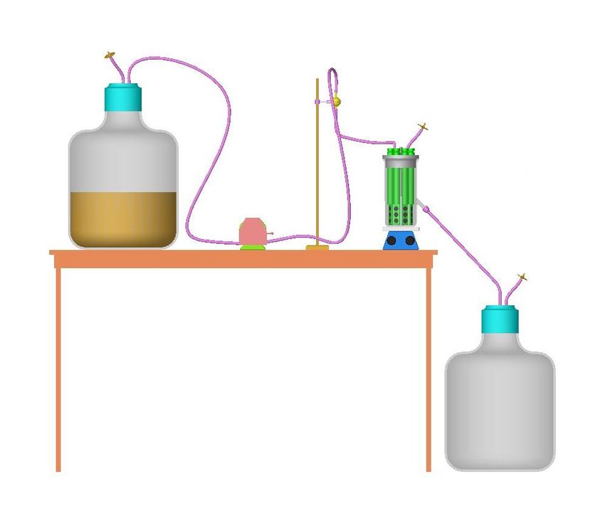
1. Purpose
The CDC Biofilm Reactor Operator’s Manual is intended to serve as a guide for researchers
interested in growing a laboratory biofilm under high shear conditions. It is the responsibility of
the user to be familiar with basic microbiological concepts and techniques. Although a specific
method is presented in the manual, the CDC Biofilm Reactor is suitable for modeling many
different environments. Laboratory biofilms are engineered based upon the dynamics in the
reactor where they grow. No one biofilm is better than any other, although one reactor may be a
better choice for modeling a particular environment. It is the responsibility of the operator to
choose which reactor best suits their research needs.

2. CDC Biofilm Reactor® Description
The CDC Biofilm Reactor (CBR), Figure 1, is a one-liter vessel with an effluent spout at
approximately 400 ml. Continuous mixing of the reactor’s bulk fluid is provided by a baffled stir
bar that is magnetically driven. An UHMW polyethylene top supports eight independent rods.
Each rod houses three removable coupons (biofilm growth surfaces) for a total of 24 sampling
opportunities. The coupons may be constructed from a variety of materials, for example:
polycarbonate, porcelain, mild steel, stainless steel, PVC, vinyl, glass, etc. The coupons
experience a consistent high shear from the rotation of the baffled stir bar. A researcher may
vary shear by altering the baffle’s rotational speed. The CBR operates as a continuous flow
stirred tank reactor (CFSTR), meaning nutrients are continuously pumped into and flow out of
the reactor at the same rate. A CFSTR offers the following advantages:
     • the bulk fluid (all the fluid in the reactor) is assumed to be well mixed (no gradients)
     • the surfaces within the reactor experience fluid shear (force opposing flow) from the
         mixing,
     • the reactor can achieve steady state conditions which eliminates all terms that depend
         upon time in the mathematical representation of the reactor. This simplifies the
         mathematics necessary to calculate the reduction in biofilm accumulation as a result of a
         treatment,
     • the residence time (time for one reactor sized volume of liquid to flow through the
         reactor) in the reactor is easily adjusted to select for biofilm growth for various species of
         bacteria,
     • the nutrient feed may be specified and adapted for various bacteria or conditions (for
         example to represent a swimming pool environment or the white water associated with
         the paper industry),
     • a portion of the reactor’s effluent (waste) may be recycled back into the reactor or
         become the feed of a second reactor,
     • with simple modifications, a CSFTR can be operated anaerobically (without oxygen).
         This increases the number of relevant environments that can be modeled using this
         design.

                                                                                                      3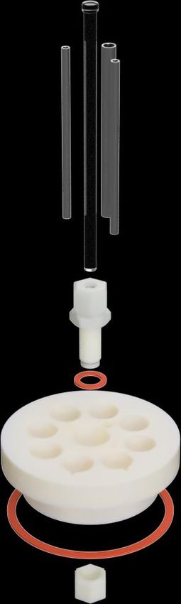
In addition to the list of advantages above, the CBR offers additional advantages:
      • the biofilm growth surfaces (a.k.a. coupons) are interchangeable with a current reactor
          that BioSurface Technology manufactures and sells,
      • 24 sampling opportunities,
      • removable rods that allow for intermittent removal, control and treated data from the
          same reactor, and
      • a baffled stirrer provides for consistent shear across all the coupons.

                                                                        Eight rods that can be
                                                                        sampled at different times
                                                                        during continuous flow

Reactor made of inert materials
                                                                        Control and treated
                                                                        coupons in the same
                                                                        reactor

          Baffle stir bar for                                           24 coupons for sampling
          consistent shear                                              opportunities, with various
                                                                        coupon materials available
                                                                        and interchangeable with RDR

                           Figure 1. Picture of the CDC Biofilm Reactor.

  3. CDC Biofilm Reactor® Standard Operating Procedure
  The CBR was designed as a flexible reactor system, meaning that it can be easily adapted to
  model a variety of conditions in the laboratory. The following standard operating procedure
  (SOP) is just one suggested use. Operators are encouraged to modify the protocol to model the
  most appropriate biofilm for their research needs. A series of notes are included in the SOP that
  alert the operator to situations where special care must be taken.

                                                                                                  4
Caution: All microorganisms should be handled according to safety recommendations for each
individual species of microorganism. Decontamination of all media and equipment used during
experimentation is required prior to disposal of media or re-use of equipment. It is the
responsibility of the operator to inform themselves on these techniques.

A. Principle
Biofilm is defined as an accumulation of bacterial cells immobilized on a substratum and
embedded in an organic polymer matrix of microbial origin. Biofilm bacteria exhibit a different
phenotype from suspended bacterial cells of the same genotype. In this method, a laboratory
biofilm is grown under high shear and continuous flow conditions. Biofilm accumulation is
quantified by harvesting the biofilm from coupons of a known surface area, disaggregating the
cells and polymer matrix, and performing viable plate counts.

B. Apparatus

      Figure 2a. Schematic of the completely assembled reactor system (Norris, 2003).

                                                                                                  5
Figure 2b. Picture of an assembled reactor system (M. Mettler, CBE, 2020).
(a) Reactor Components
i) Berzelius Pyrex Beaker: 1000mL beaker without conventional pour spout, 9.5 +/- 0.5
cm diameter. Pyrex barbed outlet spout added so that bottom is at 400 mL +/- 20mL mark.
Angle the spout 30-45 degrees to ensure drainage. Spout should accommodate silicon tubing
with ID of 8-11 mm.
NOTE 1: The rods (B.a.iii) and baffle (B.a.v) will displace approximately 50 mL of liquid when
the system is completely assembled. Therefore, an outlet spout at the 400 mL mark will result in
a volume of approximately 350 mL during operation. Before beginning an experiment, confirm
the actual reactor operating volume when the reactor is fully assembled.
ii) Reactor top, Figure 2: UHMW polyethylene top equipped with 3 holes
accommodating 6-8 cm long pieces of stainless steel or other rigid autoclavable tubing with OD
of 5-8 mm for media inlet, air exchange and inoculation port. Center hole, to accommodate the
glass tubing used to support the baffle assembly (B.a.v). Eight rod holes notched to
accommodate stainless steel rod alignment spike. Rubber gasket, to fit between reactor top and
reactor beaker.
6Figure 2. Expanded schematic of reactor top.
iii) Polypropylene rods, Figure 3: Eight polypropylene rods, machined to hold three
coupons (B.a.iv) at the immersed end. 316 Stainless Steel set screws imbedded inside to hold
coupons in place. Rods fit into holes in reactor top and lock into preformed notches.
iv) Polycarbonate coupons, Figure 3: Provide a surface for biofilm growth. Twenty-four
cylindrical polycarbonate coupons with a diameter of 1.27 cm, thickness of approximately 3.0
mm.
7Figure 3. Expanded schematic of coupon rod and coupons.
v) Stir Blade Assembly (Baffle), Figure 4: To create constant shear/mixing. Teflon blade)
fitted into cylindrical Teflon holder and held in place with a magnetic stir bar. Teflon holder fits
onto a glass rod, Figure 2, fitted into the reactor top. The glass rod is held in place with a
compression bulk-head fitting and acts as a support for the moving blade assembly.
8Figure 4. Expanded schematic of baffled stir bar.
(b) Glass Flow break: Autoclavable and accommodating tubing of ID 3.2 mm. Insert vertically
into media inlet tube to prevent contamination from reactor to media carboy.
(c) Silicone tubing: Two sizes of tubing, one with ID 3.2 mm (port OD=4.75 mm) and the other
with ID 7.9 mm (port OD=7.94 mm). Both must withstand sterilization. Use to connect media
carboy to reactor inlet; beaker outlet to waste carboy; air vent to reactor top; media carboy air
vent.
(d) Carboy: Two 20L autoclavable carboys for media and waste.
(e) Carboy Tops: Two threaded tops each equipped with 2 barbed fittings to accommodate
tubing ID 3.1 mm for nutrient or waste line and air vent attachment.
(f) Magnetic Stir plate: Capable of operation at 100-400 rpm. A digital stir plate is recommended.
(g) Pipette: Capable of accurately dispensing 1.0 mL.
(h) Micropipette: Capable of accurately dispensing 0.01 mL.
(i) Top Loading Balance: For weighing reagent ingredients; sensitive to 0.01 gm.
(j) Homogenizer Probe: Capable of mixing at 20,500 +/- 5000 rpm in a 5-10 mL volume and able
to withstand autoclaving or other means of sterilization.
(k) Vortex: Any vortex mixer that will ensure proper mixing of culture tubes.
(l) Peristaltic Pump: For pumping media into reactor during continuous flow phase; pump head
capable of holding selected tubing (accommodates tubing ID/OD).
(m) Wooden Applicator Sticks: Used for scraping biofilm from coupon surface. Sterile. (n)
Hemostat: Stainless steel hemostat clamp with curved tip to remove and hold coupon in place
while scraping. Use after flame sterilizing.
(o) Inoculating Loop. Used to introduce bacteria into inoculum flask. Sterile
(p) Bunsen or Alcohol burner: For flame sterilizing inoculating loop and hemostat.
(q) Culture Tubes with caps: Any with a volume capability of 10 mL and diameter no less than 6
cm. Recommended size is 16 x 125mm borosilicate glass with threaded opening.
(r) Sterilizers: Any steam sterilizer capable of producing the conditions of sterilization.
(s) Colony Counter: To aid in counting plates.
(t) Clamp Stand and Clamp: To hold glass flow break and media inlet tube vertically above
reactor top. Clamp with 0.5 cm minimum grip size.
(u) Petri Dish: 100 x 15mm, plastic, sterile, for transporting rods from reactor to workstation.
9(v) Plexiglas Board: Or other surface, used as a sampling platform on which to hold and scrape
samples. Use after disinfecting with 70% EtOH.
(w) Environmental Shaker: Capable of maintaining temperature of 37˚C.
C. Media and Reagents
NOTE 2: All reference to water as diluent or reagent means distilled water or water of equal
purity.
(a) Inoculum culture media: 100mL of 300mg/L soybean-casein digest media or an equivalent
general bacterial growth medium. Tryptic soy broth is recommended. Sterilize for 20 minutes.
Inoculate media with a single colony from a bacterial isolation plate using sterile inoculating
loop. Pseudomonas aeruginosa (ATCC 700888) is the bacteria used in this method. Incubate at
35+/- 2˚C while shaking for 18-24 h.
(b) Batch culture media: 500mL of 300mg/L TSB. Sterilize in reactor for 20 minutes.
(c) Continuous flow media: 20L of 100mg/L TSB. Sterilize 20L of water then aseptically add
concentrated broth (2.0 gm TSB/500mL, sterilized 20 minutes) so that the final volume equals
20 L and final concentration equals 100 mg/L.
(d) Buffered Dilution Water: 0.0425 g/L KH2 PO4 distilled water, filter sterilized and 0.405 g/L
MgCl·6H2O distilled water, filter sterilized. Aseptically fill sterile, capped test tubes with 9 mL of
sterile dilution water.
(e) Bacterial Plating Medium: R2A agar is recommended.
(f) 95% Ethanol: For dipping hemostat prior to flame sterilizing.
(g) 70% Ethanol: For rinsing homogenizer probe and general bench top clean up.
D. General Instructions
a. Reactor Preparation
i) Clean reactor coupons by immersing in a 1:1000 dilution of laboratory soap and
sonicating for 3-5 minutes. Rinse with tap water until no more soap appears then
sonicate again in reagent grade water. A final 2-hour soak in 2M HCl is recommended
then a final rinse with reagent water (do not soak hydroxyapatite or other acid
susceptible coupons in HCl; see NOTE 3). Let coupons air dry. Place a coupon into
each hole of the reactor rod, leaving the top of the coupon flush with the inside rod
surface (sampled surface). Hold in place by tightening the set screw adjacent to the
hole.
NOTE 3: Check for material compatibility before soaking coupons in 2 M HCl. Some coupon
materials, such as hydroxyapatite, carbon steel, or stainless steel, should not be soaked in 2M
HCl. If the material is incompatible with this acid, investigate alternative cleaning solutions.
NOTE 4: Visually inspect coupon surface topography for any deformations before using.
Discard damaged coupons.
ii) Assemble all reactor parts including rods, coupons, baffle, bacterial air vent and
tubing. Air vent and tubing are attached to the rigid tubes in the reactor top (B.a.ii). Use a
small piece of flexible tubing to attach the air vent to the reactor top. Check assembly on
stir plate to ensure baffle rotates without scraping rods. Clamp effluent tube. Foil the
exposed ends of all tubing.
iii) Add 500 mL non-sterile batch culture media (C.b). Sterilize reactor system using an
autoclave for 20 minutes at 121°C.
10NOTE 5: Autoclaving longer than 20 minutes could cause unnecessary degradation to the
reactor or its components and is not advised. The reactor and its components have not been
approved for temperatures above 121°C, and any damage caused by a higher temperature will
not be covered under warranty.
b. Batch Phase
i) Place reactor on stir plate. Be sure gases may pass freely through the bacterial air
vent and effluent tubing is clamped shut.
ii) Aseptically inoculate the reactor by injecting 1mL of previously prepared inoculum
culture (C.a) into the batch media through an inoculum port in reactor top.
NOTE 6: The viable bacterial density of the inoculum should equal 108 cfu/mL. Confirm this
number by diluting and plating a sample from the inoculum flask.
iii) Start the baffle rotating at 125 ± 5 rpm.
NOTE 7: The speed at which the baffle rotates directly determines the amount of shear stress
that the biofilm experiences. Ruggedness testing showed that biofilm accumulation on the
coupons is sensitive to changes in the baffle’s rotational speed. The baffle rotational speed is
a critical factor that must be controlled. If a digital stir plate is not available, then use a
strobe light to confirm rotational speed.
iv) Operate the reactor in batch phase for 24 hours.
c. Continuous Flow Phase
i) Aseptically connect the nutrient tubing line to the carboy containing the continuous flow
nutrient broth (C.c).
ii) Remove foil and place the end of the effluent tubing into a waste carboy, unclamp.
iii) Pump a continuous flow of media into the reactor at a flow rate equal 11.67 + 0.2
ml/min.
NOTE 8: Flow rate is calculated by dividing the reactor volume by the residence time.
The residence time is 30 minutes. The reactor volume is approximately 350 ml, see
NOTE 1. The operator should set an exact flow rate based upon the measured fluid
volume in the reactor when the baffle, rods, and coupons are in place to achieve an
exact 30-minute residence time. The reactor residence time is a critical parameter that is
specific to the bacterial species used during the experiment. To select for biofilm growth
in the reactor, the residence time must be less than the doubling time for the suspended
cells. This will result in the suspended cells washing out of the reactor, leaving only
biofilm.
iv) The reactor is operated with continuous flow for 24 hours.
E. Sampling
a. Sampling Coupons
i.) Set-up sampling materials: vortex, homogenizer, culture tubes, pipettes, wooden
sticks, flame sterilized hemostat, sampling platform.
ii.) Turn off stir plate and pump.
11iii.) Remove a single rod by pulling straight up. Collect any drips in a sterile petri plate
held beneath rod.
iv.) Loosen set screw to release coupon and remove using flame sterilized hemostat,
being careful not to disturb the biofilm on coupon surface that will be scraped.
v.) Hold coupon in place on a disinfected Plexiglas Board with hemostat and scrape the
side of the coupon that faced the baffle with a sterile wooden stick. Hold the stick
perpendicular to the surface when scraping.
vi.) Remove cap of first 9 mL dilution tube and rinse stick by swirling and tapping on
bottom of tube. Repeat scraping and rinsing steps 3 to 4 times.
vii.) Hold coupon above dilution tube and rinse scraped surface with 1 mL dilution water.
The total volume in the tube equals 10 mL. Record this number as the volume scraped
into (Equation [1]).
b. Disaggregation
i.) Homogenize the dilution tube containing sample at 20,500 rpm for 30 s using sterile
homogenizer probe.
ii.) Clean the probe between samples by rinsing for 30 s at 20,500 rpm in a sterile
dilution blank followed by a rinse at 20,500 rpm for 15 s in 75% ethanol. Let the probe
soak in ethanol for 1 min. Rinse probe two more times with dilution blanks at 20,500 rpm
for 30 s each.
NOTE 9: Homogenization breaks up biofilm clumps to form a homogeneous cell suspension.
Improper disaggregation will result in an underestimation of viable cells present in the sample.
c. Serial Dilution
i.) Serially dilute the disaggregated biofilm sample according to standard microbiological
techniques.
d. Viable Colony Counts
i.) Plate each dilution in duplicate on R2A nutrient agar. Any standard plating technique,
such as spread plating or drop plating, is acceptable.
ii.) Incubate plates at 35 +/- 2˚C for 18-24 hours.
iii.) Count the appropriate number of colonies for the plating method used.
F. Calculations
a) Calculate the log density for one coupon using Equation [1]:
mean cfu
cfu
LOG10 2 = LOG10
plate volumescraped in to (dilution ) [1]
cm vol. of sample plated surface area scraped
b) The mean biofilm density is the average of the individual coupon log densities.
124. Repeatability
For the CBR SOP, the estimated within-experiment variance is 0.1980 and the estimated
between-experiment variance is 0.1461. The estimated repeatability standard deviation is
0.5866 of which 58% is attributable to within-experiment variation and 42% is attributable to
between-experiment variation. This repeatability standard deviation pertains to a protocol that
samples only one coupon per experiment. The repeatability standard deviation for a protocol
that requires sampling n coupons per experiment is sqrt[(0.1980 / n) + 0.1461]. For example, if
the protocol specifies n=3 coupons and the reported log density is the mean of the three
individual coupon log densities, then the repeatability standard deviation is 0.46 of which 31% is
attributable to within-experiment variation and 69% is attributable to between-experiment
variation.
5. Troubleshooting
1. Always check the alignment of the rubber gasket, Figure 2.
2. Visually confirm that the inoculum reaches the reactor’s bulk fluid.
3. The top of the glass rod is the end with the expanded head, Figure 2. This design holds the
baffle in the center of the reactor while allowing it to rest on the bottom for proper mixing.
4. Tighten coupon set screws before the reactor is autoclaved to ensure correct alignment.
5. If a rod pops out of the reactor during autoclaving, immediately push it back into the reactor
top and continue with experiment unless the operator suspects the reactor’s sterility is
compromised, then start over from the beginning of the protocol.
6. Always ensure that the reactor’s effluent spout allows for proper draining.
7. If rod alignment peg falls out, Figure 3, replace before beginning an experiment.
8. Confirm that the bacterial air vent is working properly before an experiment begins, so that
the reactor can exhaust during autoclaving.
6. CDC Biofilm Reactor® Standard Methods
A. ASTM (www.astm.org)
a. ASTM E2562
Standard Test Method for Quantification of Pseudomonas aeruginosa Biofilm Grown
with High Shear and Continuous Flow using CDC Biofilm Reactor
b. ASTM E2871
Standard Test Method for Evaluating Disinfectant Efficacy against Pseudomonas
aeruginosa Biofilm Grown in CDC Biofilm Reactor using Single Tube Method
B. USEPA (www.epa.gov)
a. MB-19
Growing a Biofilm using the CDC Biofilm Reactor
b. MB-20
Single Tube Method for Determining the Efficacy of Disinfectants against Bacterial
Biofilm
137. CDC Biofilm Reactor® Assembly
NOTE: The CDC Biofilm Reactor System (CBR 90) comes with and without a stir plate and
support stand. These assembly directions assume a stir plate and support stand are used.
1 Stir Plate and Support Stand:
1.1 Fix the aluminum rod into the back of the stir plate in the support clamp.
1.2 Mount the support ring in a clamp and attach to the support rod. Mount the ring
low on the stand near the top of the stir plate.
1.3 Mount the 3-prong clamp onto the support rod with a clamp. Mount the 3-prong
clamp high on the support rod.
2 Reactor Assembly:
2.1 Nutrient Supply Tubing: Attach tubing from your media reservoir to the glass flow
break inlets.
2.2 Attach effluent tubing. Use minimum 1/4"(6 mm) ID and direct the effluent tubing
to the drain or collection reservoir.
2.3 Insert the coupons into the coupon rods, flush with the inner rod surface.
2.4 Insert the rotor into the glass reactor vessel.
2.5 Mount the reactor lid onto the glass vessel while inserting the glass rod into the
center of the blade rotor.
2.6 Insert the glass vessel bottom through the stand ring support. Adjust the location
of the ring support to center the glass vessel in the middle of the stir plate.
2.7 Adjust the 3-prong support clamp to hold the influent tubing and glass flow
breaks above the reactor vessel.
2.8 Insert rod coupon holders into the reactor vessel through the top access ports.
Turn the coupon holders so the face of the coupons is perpendicular to the blade
on the vane rotor (stainless steel alignment pin aligns with slot on the reactor lid)
and push the coupon holders down into the ports.
148. CDC Biofilm Reactor® Ancillary Equipment List
NOTE: BioSurface Technologies does not sell or supply the ancillary equipment described
below. This or comparable equipment is required to complete the reactor system set-up. Please
check with your local vendors for availability and current pricing. Equipment listed is not
recommended equipment, but an aid to help you identify compatible equipment.
Pump: There are many types of peristaltic pumps available and you may opt for alternative
types and pump head configurations (multi-channel versus single channel, higher/lower rpm
range, etc.). Depending on what you need to add to the reactor during operation, you may
require more than 1 pump or a multi-head pump (media for growth and biofilm treatment
chemical for some duration that may require an additional pump).
- Masterflex L/S Precision Modular Drive w/ Remote I/O; 100 rpm
(Cole Parmer P/N WU-07557-10 VAC CE certified)
- Masterflex L/S Easy-Load II Head for Precision Tubing, PPS/SS
(Cole Parmer P/N EW-77200-60)
Tubing: The tubing you choose depends on the chemical compatibility, gas permeability, wear
resistance in peristaltic pumps, and pricing. You must choose the tubing that best fits your
needs. C-Flex tubing (listed below) is similar to silicone tubing but has a low gas-permeability
compared to silicone. If gas-permeability is not an issue, standard silicone tubing is acceptable.
- Masterflex, C-Flex (50 A), L/S 16, 25 ft. (Cole Parmer P/N EW-06424-16)
• Will fit the 3/16” barbed port fittings on the top of the CBR and connect to the
media supply reservoir.
- Masterflex, C-Flex (50 A), L/S 18, 25 ft. (Cole Parmer P/N EW-06424-18)
• Used to connect the effluent port (3/8” barbed port) on the reactor to the
spent media collection vessel.
- Masterflex, C-Flex (50 A), ¼” ID x 7/16” OD, 25 ft
(Cole Parmer P/N EW-06424-72)
• A few lengths and adapters to get from the carboy to the smaller diameter
tubing, and as a siphon tube inside the carboy.
- Nylon 1/4” x 1/8” adapter (Cole Parmer P/N EW-30622-28)
• Needed to get from the 3/16” or 1/4” ID to the 1/8” tubing.
Carboy: The carboy should be selected based on experiment needs and may be larger or
smaller than what is suggested below. Ported lids can be purchased from suppliers, but
standard lids are easily converted to ported lids using the following fittings or similar.
- Cole-Parmer Heavy-Duty PP Carboy with Shoulder Handle, 10 L
(Cole Parmer P/N EW-62507-10)
- Filling / Venting ports for carboy lid - 1/4” tubing
(Cole Parmer P/N EW-06259-10)
- Filling / Venting ports for carboy lid - 1/2” tubing
(Cole Parmer P/N EW-06259-00)
Suggested Ancillary Equipment Suppliers:
Cole Parmer: 800-323-4340 (www.coleparmer.com)
Fisher Scientific: 1 800-766-7000 (www.fishersci.com)
159. RTD Temperature Probe
(for use with the digital stir/hot plate)
The CDC Biofilm Reactor with Stir/Hot Plate is provided with an RTD Temperature Sensor for
temperature control of the Stir/Hot Plate. The standard part provided for the RTD Sensor is an
RTD sensor well (P/N CBR 2218). The location of the temperature sensor in the reactor vessel
is critical to providing an accurate temperature measurement of the liquid media within the
reactor. This well consists of nylon, 316 stainless steel, or anodized aluminum tubing sealed at
the bottom. The well allows insertion of the sensor into the reactor vessel but does not directly
contact the liquid. This location of the RTD Sensor allows accurate temperature control but
reduced temperature change response times. Allow extra time for the stir/hot plate to bring the
temperature within the vessel to the desired set-point. Remove the sensor from the well prior to
autoclaving the vessel. To increase response times, the well can be partly filled with an oil or
other liquid that allows for better temperature conductivity to the probe inside the well.
ALTERNATE RTD SENSOR LOCATIONS
T-Fitting on Effluent Port: The RTD sensor tip can be placed in contact with the effluent flow
by using a t-fitting to attach to the effluent port of the glass vessel. At higher temperature
operations, the sensor may need to be inserted into the reactor vessel to provide accurate
temperature control. The RTD sensor may be inserted into the effluent port using the t-fitting
(inserted the length of the base of the tee, with the effluent flow exiting to the waste collection
vessel through the perpendicular port on the t-fitting; make sure the fitting, sensor seal, and
vessel port are liquid tight prior to operation).
To create this t-fitting setup for effluent flow temperature measurement, use a ½-inch
barbed t-fitting (preferably nylon or another autoclavable plastic). Cut a short section of ½-inch
silicone tubing and attach to one side and the top of the fitting. Cut another length of 3/8-inch
OD silicone tubing and insert into the top of the ½-inch tubing until it bottoms out. Cut another
length of ¼-inch silicone tubing and slide it onto the temperature probe, and then insert the
probe with tubing into the top of the t-fitting. This stacked-tubing method should create a good
seal to prevent leaking. The entire fitting can then be attached to the effluent barbed port.
Through a Coupon Holder Rod Port: The RTD sensor may be mounted through one of the
top ports (coupon holder rod ports) using a properly sized tapered hole stopper, bored to fit the
temperature probe. This location allows direct contact of the reactor media to the temperature
sensor and will provide the most accurate temperature control.
1610. RTD Temperature Probe Well Installation
(for use with the digital stir/hot plate)
The central glass shaft can be replaced with an RTD sensor well (P/N CBR 2218). This well
consists of rigid nylon, 316 stainless steel, or anodized aluminum tubing sealed at the bottom.
The well allows insertion of the sensor into the reactor vessel but does not directly contact the
liquid. This location of the RTD sensor allows accurate temperature control, but reduced
temperature change response times.
To replace the glass shaft with the temperature well, two 11/16” sockets (6-point, 18 mm) and
socket drive are required. Place one of the sockets in a vise, pointing up. Insert the CDC lid with
glass shaft into the immobilized socket and align the hex nut on the bottom side of the lid into
the hex socket. Place the other socket onto the hex nut on the top of the lid. Using the socket
driver, turn the nut and lid counterclockwise to loosen the bottom nut. Remove the bottom nut (If
the top nut loosens before the bottom nut, place a flat bladed screw driver into the lid recess
next to the compression fitting holding the glass rod and apply pressure to the screw driver to
prevent the compression fitting from rotating, while turning the lid counter-clockwise. This
rotation will loosen the compression nut on the bottom of the lid.). Press the bulkhead
compression fitting out of the lid (the bulkhead compression fitting is not threaded to the lid).
Insert the new bulkhead fitting with sensor well and compression gasket installed into the lid and
install the bottom hex nut. Place the lid onto the socket held in the vise and tighten the top hex
nut using the socket and driver just until the top bulkhead gasket is compressed (remove the top
socket, look down into the compression fitting recess. The compression gasket will start to bulge
out when it is compressed. Over-compression will cause the gasket to bulge on one side
significantly and un-seat the gasket from between the two mating surfaces).
The RTD sensor well should now be ready for use. The RTD sensor will slide into the well from
the top of the reactor. The RTD sensor does not directly contact the liquid in the vessel, which
reduces its response time. Allow extra time for the stir/hot plate to bring the temperature within
the vessel to the desired set-point. Remove the sensor from the well prior to autoclaving the
vessel.
1711. Anaerobic CDC Biofilm Reactor® Assembly and Operation
Do Not Pressurize or Operate Under Vacuum
The CDC Biofilm Reactor Lid Modification for anaerobic gas containment does not make the
CDC Biofilm Reactor a pressure or vacuum containment vessel. The seals added to the lid are
to aid in containment of anaerobic gases and to reduce oxygen migration into the vessel during
anaerobic microbial growth. The CDC Biofilm vessel should always be vented.
The rubber flange gasket on the underside of the reactor lid can be torn easily. Ensure that the
setscrews on the coupon holder rods are not protruding from the sides of the holder rods before
inserting them into the reactor lid.
BioSurface Technologies does not recommend autoclaving with the lid clamps in place, nor is
this necessary. All components of the Anaerobic CDC Reactor (CBR 90-3) are autoclavable and
re-useable.
Assembly Instructions
The modified lid system includes an O-ring seal and compression flanges, and a silicone flange
gasket on the underside of the reactor lid. The silicone flange gasket will provide a light seal
around each coupon holder rod when they are fully inserted into the lid. The compression rings
and silicone O-ring, along with four stainless steel wingnuts, create a seal between the lid and
the glass vessel.
The bottom compression ring (with screws mounted in four holes) should be lowered over the
top of the glass vessel so that the screws are facing up. The plastic split ring is installed over the
top of the glass vessel by opening the ring slit and working the ring over the glass vessel lip.
The silicone O-ring is installed around the top of the glass vessel near the vessel lip. The top
compression ring is placed over the top of the CDC Biofilm Reactor lid after it is installed, and
the 4 holes are aligned with the screws on the bottom compression ring. The 4 wingnuts are
then used to compress the rubber O-ring and underside of the reactor lid (avoid over-tightening
the wingnuts by tightening them evenly around the lid to a finger-tight fit).
The lid ports on the Anaerobic CDC Biofilm Reactor have been replaced with polymer tubing.
The coupon holder rod setscrews are 316 stainless steel and are not compatible with all
anaerobic gases or anaerobic conditions (they will corrode under H2S or acidic anaerobic
conditions). A set of nylon setscrews have been provided as replacement items for conditions
which are not compatible with the stainless steel.
A clamp or containment ring should be used when mounting the reactor on a stir plate to
prevent the reactor from tipping (the anaerobic containment system makes the reactor
somewhat top-heavy).
18You can also read