Characterisation of a multi-view fringe projection system based on the stereo matching of rectified phase maps
←
→
Page content transcription
If your browser does not render page correctly, please read the page content below

Measurement Science and Technology

PAPER • OPEN ACCESS

Characterisation of a multi-view fringe projection system based on the
stereo matching of rectified phase maps
To cite this article: A Shaheen et al 2021 Meas. Sci. Technol. 32 045006

View the article online for updates and enhancements.

                               This content was downloaded from IP address 46.4.80.155 on 08/09/2021 at 17:11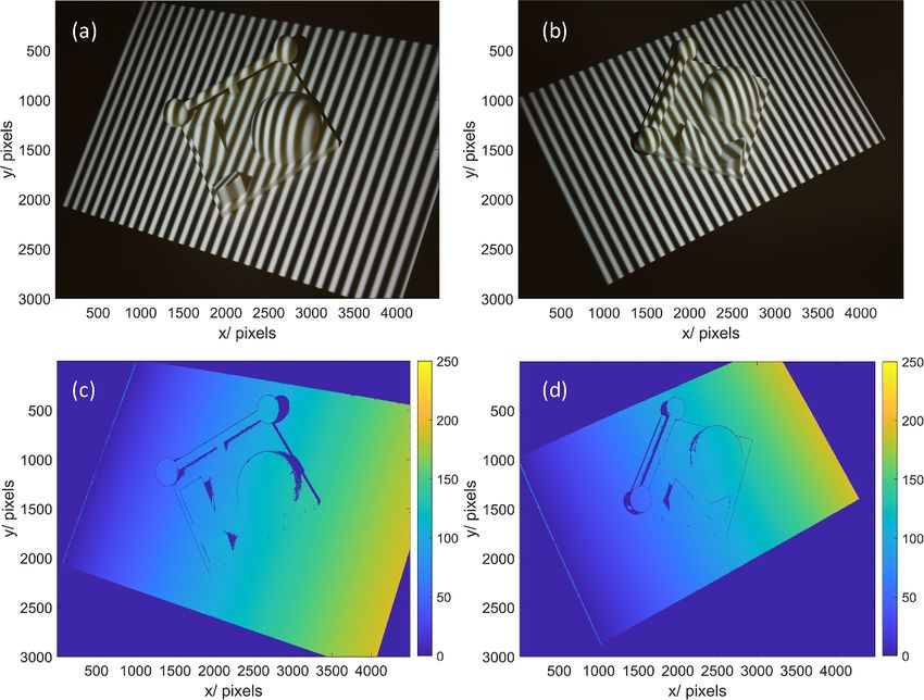
Measurement Science and Technology
Meas. Sci. Technol. 32 (2021) 045006 (14pp) https://doi.org/10.1088/1361-6501/abd445
Characterisation of a multi-view fringe
projection system based on the stereo
matching of rectified phase maps
A Shaheen1, D Sims-Waterhouse2, P Bointon3, S Takushima4, S Piano1 and R K Leach1,2
1
Manufacturing Metrology Team, Faculty of Engineering, University of Nottingham, Nottingham NG8
1BB, United Kingdom
2
Taraz Metrology, Nottingham, United Kingdom
3
Texture Jet, Nottingham, United Kingdom
4
Advanced Technology R&D Center, Mitsubishi Electric Corp., 8-1-1 Tsukaguchi-Honmachi,
Amagasaki Hyogo 661-8661, Japan
E-mail: amrozia.shaheen2@nottingham.ac.uk
Received 14 October 2020, revised 2 December 2020
Accepted for publication 16 December 2020
Published 16 February 2021
Abstract
Multi-view fringe projection systems can be effective solutions to address the limitations
imposed by the limited field of view, line-of-sight issues and occlusions when measuring the
geometry of complex objects, associated with single camera–projector systems. However,
characterisation of a multi-view system is challenging since it requires the cameras and
projectors to be in a common global coordinate system. We present a method for characterising
a multi-view fringe projection system which does not require the characterisation of the
projector. The novelty of the method lies in determining the correspondences in the phase
domain using the rectified unwrapped phase maps and triangulating the matched phase values to
reconstruct the three-dimensional shape of the object. A benefit of the method is that it does not
require registration of the point clouds acquired from multiple perspectives. The proposed
method is validated by experiment and comparison with a conventional system and a contact
coordinate measuring machine.
Keywords: optical form metrology, 3D imaging, fringe projection method, Stereo matching
(Some figures may appear in colour only in the online journal)
1. Introduction single camera–projector pair have limitations when acquir-
ing the 3D form in one acquisition due to the small field of
Fringe projection is a structured light method that is used view of the camera, the frequent presence of occlusions and
for industrial three-dimensional (3D) measurement due to its potentially high slope angles, especially for the freeform geo-
fast acquisition rates and non-contact, non-destructive nature. metries of additively manufactured (AM) parts [7]. A pos-
Fringe projection has been used in a variety of sectors, such as sible solution to alleviate these limitations is to include mul-
manufacturing quality control [1, 2], biomedicine [3], reverse tiple cameras and projectors and acquire multiple views from
engineering [4], aerospace [5] and automotive [6]. However, multiple perspectives. Multi-view systems have become an
commercially available fringe projection systems based on a emerging research area in 3D form measurement. However,
multi-view systems are more complex than single camera–
projector systems and require not only the individual com-
ponents to be characterised but also the structural relationship
Original Content from this work may be used under the
between the components (cameras and projectors) to define
terms of the Creative Commons Attribution 4.0 licence. Any
further distribution of this work must maintain attribution to the author(s) and a global coordinate system and merge the data from multiple
the title of the work, journal citation and DOI. perspectives.
1361-6501/21/045006+14$33.00 1 © 2021 The Author(s). Published by IOP Publishing Ltd Printed in the UK
Meas. Sci. Technol. 32 (2021) 045006                                                                                         A Shaheen et al

    In multi-view systems, the characterisation (often called            by a phase-stepped fringe projection technique [23–26]. How-
calibration in practice) has a decisive influence on the sys-            ever, if the camera pixels are not aligned with the projector
tem performance and for accurate 3D surface reconstruction.              pixels, this can lead to a mapping error. In general, any error in
Abedi et al proposed a method of geometric calibration and               the camera characterisation is transferred to the projector char-
rectification of a circular multi-camera system using a pyramid          acterisation, which can significantly affect the performance
object with symmetric triangles and opposite colours. The                and accuracy of the fringe projection system. In this paper,
method processes all the cameras simultaneously and solved               we present a novel method to characterise a multi-view fringe
the issue of error accumulation [8]. Liu et al used a 3D target to       projection system, which does not require projector character-
characterise a multiple depth camera system using lidar scan-            isation, therefore, the influence of mapping error is removed.
ning. The method determines the relative orientation between             The proposed method depends on the stereo matching between
the cameras with limited overlapping fields of view and unifies          rectified unwrapped stereo phase maps based on the epipolar
the multi-camera coordinates in the same coordinate system               constraints. In general, the stereo vision and fringe projec-
[9]. Sun et al developed a method of global characterisation             tion methodologies are combined to acquire the dense dispar-
of a multi-camera system using a group of spherical targets.             ity map which is incorporated with the stereo-camera charac-
This one-time operation can globally characterise all the cam-           terisation information for 3D surface reconstruction [27–30].
eras with non-overlapping fields of view and avoids extens-              However, the proposed method relies on determining the cor-
ive workloads and accuracy loss caused by repeated processes             respondences in the phase domain. The absolute phase maps
[10]. A flexible method of global characterisation of multiple           are acquired through the fringe projection method and the
cameras using a transparent glass checkerboard was proposed              matched phase points in the stereo phase maps are triangu-
by Feng et al [11]. The method utilises the refractive projec-           lated for 3D reconstruction. The effectiveness of the proposed
tion model and the concept of ray tracing to eliminate the error         method is determined by finding the point-to-point distance
of refraction and to achieve high accuracy.                              deviations between the point clouds, which are acquired from
    The characterisation of a multi-view fringe projection sys-          different views. The results are compared with the contact
tem is based on determining both the intrinsic and extrinsic             coordinate measuring machine (CMM) measurements which
properties of the cameras and projectors and bringing them               serve as a reference for the dimensional measurements. A
into the global frame of reference. A common approach to                 comparison of the proposed method with the conventional
multi-view system characterisation is the extension of the               method of characterising the multi-view fringe projection sys-
methods for characterising single camera–projector systems,              tem is also presented.
proposed by Tsai, Zhang, and Huang [12–15]. Where each
camera is characterised with an accurately manufactured tar-
                                                                         2. Methodology
get (for example, a checkerboard or circle board) and the rela-
tionship between the multiple views is obtained by global
                                                                         The methodology of this work falls into five main stages: Step
optimisation of the extrinsic parameters of all the views.
                                                                         A—Camera characterisation, Step B—Phase map by fringe
Albers et al presented a flexible characterisation method for
                                                                         projection, Step C—Rectification of the unwrapped phase
a multi-sensor fringe projection system by incorporating the
                                                                         maps, Step D—Stereo matching of the rectified unwrapped
Scheimpflug optics for the cameras and defining a com-
                                                                         phase maps and Step E—Three-dimensional reconstruction.
mon world coordinate system using a planar target [16]. Gai
                                                                         The schematic is shown in figure 1.
et al proposed an easy-to-use characterisation of a multi-
                                                                             Step A—Camera characterisation: The camera character-
view fringe projection system, where the digital fringe pro-
                                                                         isation is performed by placing a checkerboard in the field of
jection and phase maps are used to acquire global charac-
                                                                         view of all the cameras (there are four in our example set up—
terisation [17]. Gdeisat et al [18] and Deetjen et al [19]
                                                                         see section 3). Images of the checkerboard at different orient-
developed the global characterisation methods for multiple
                                                                         ations are captured by all cameras. Each camera is character-
camera-projection systems, whereby the cross-talk between
                                                                         ised separately using a pinhole camera model [12–15]. The
multiple camera-projector pairs is avoided by using a particu-
                                                                         intrinsic and extrinsic parameters of each camera are determ-
lar light bandwidth (RGB optical colour filters). Deejtan et al
                                                                         ined using a developed image processing algorithm in MAT-
also demonstrated the technique for high-speed 3D reconstruc-
                                                                         LAB [31].
tion of a flying bird. Servin et al combined the two techniques:
                                                                             After characterising each camera individually, the stereo-
co-phased profilometry and 2-step temporal phase unwrap-
                                                                         camera parameters are generated using the camera charac-
ping, and measured an industrial metallic discontinuous object
                                                                         terisation information [32–39]. In general, any number of
which is coated with white-matte paint to reduce the specu-
                                                                         pairs could be used; however, due to the lack of a common
lar reflection [20, 21]. A co-phased 2-projector and 1-camera
                                                                         field of view and the area illuminated by the structured light,
based 360-degree profilometer was proposed which can meas-
                                                                         we have considered the adjacent camera pairs and treated
ure highly discontinuous objects [22]. A plastic skull is meas-
                                                                         the multi-view system as two sets of stereo-camera pairs.
ured by rotating it with ϕ rotation steps.
                                                                         The transformation between the stereo-camera pairs is given
    In typical fringe projection systems, the projector is mod-
                                                                         by [40]:
elled as an inverse camera, the camera is used to capture
images for the projector and the transformation from the cam-
era image pixels to the projector image pixels is carried out                     R2→1 = R2 (R1 )T , T2→1 = T2 − (R2→1 T1 ),            (1)

                                                                     2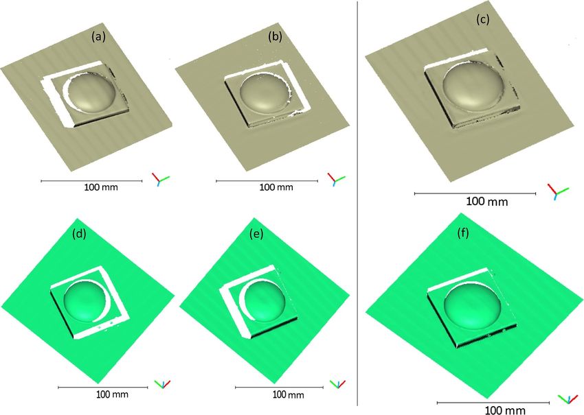
Meas. Sci. Technol. 32 (2021) 045006                                                                                          A Shaheen et al

                   Figure 1. Schematic diagram of the characterisation method of the multi-view fringe projection system.

                                                                           has 2π modulation and is unwrapped by removing the 2π dis-
                                                                           continuities and acquiring a continuous phase map.
          R4→3 = R4 (R3 )T , T4→3 = T4 − (R4→3 T3 ),             (2)
                                                                               We have used temporal phase unwrapping [42–45] to pro-
                                                                           duce an absolute phase map. In temporal unwrapping, the
where R and T are the rotation and translation matrices respect-           fringe order is encoded into binary fringes and projected onto
ively and correspond to the extrinsic parameters that describe             the object, and an absolute unwrapped phase map is acquired.
the transformation from the world coordinate system to the                 A modification to the binary fringes is introduced by con-
camera coordinate system. The superscript T in (R1 )T and                  verting the binary values to greyscale values, which simpli-
(R3 )T represents the transpose. The relative orientation and              fies the search for 2π discontinuities in the phase map with
location in each stereo-camera pair is defined with respect to             respect to the neighbouring pixels. The unwrapping errors
the first checkerboard position, which is in the common field              in the retrieved phase maps are corrected using a filtering
of view of the cameras and corresponds to the same global                  algorithm that convolves the unwrapped phase map with a
coordinate system. The first dataset has the checkerboard in               Sobel edge kernel and removes the random spikes and dips
the field of view of all cameras, therefore, it removes the need           in the phase map.
for the checkerboard to be visible to all cameras at all times.                Step C—Rectification of the unwrapped phase maps: One
    Step B—Phase map by fringe projection: A fringe pro-                   approach to triangulate a large number of points is to rectify
jection system can be mathematically modelled as a stereo-                 the stereo images and estimate the disparity map. Rectifica-
camera system and relies on triangulation of common points                 tion is a transformation applied to the images to project them
between the projector and the camera. Essentially, one camera              onto the same plane and can account for camera distortion and
in the stereo pair is replaced with a projector and the corres-            the non-coplanar stereo-camera pair [46, 47]. A schema of the
pondence is determined by the characteristics of the projected             rectification process is shown in figure 2, which shows that the
structured light. In this work, the method of phase encoding               image rectification transforms each image such that the epi-
is based on the phase-stepped fringe projection method [26].               polar lines (shown as dotted lines in figure 2) are parallel. The
A set of phase-stepped sinusoidal and binary encoded fringe                epipolar lines are given by:
patterns [41] are projected onto the surface of the object being
                                                                                                     lL = F T ϕ R ,                      (3)
measured. Different phase offsets are applied to the sinusoidal
pattern and an image is captured at each step. The phase value
at any particular pixel can be determined from the captured N
phase-stepped sinusoidal images [23–26]. The retrieved phase                                         lR = FϕL ,                          (4)

                                                                       3
Meas. Sci. Technol. 32 (2021) 045006                                                                                              A Shaheen et al

                                                                            for the nearest neighbour (row/line) in the right phase image to
                                                                            each point in the query data (point in the left phase image) is
                                                                            accomplished using an exhaustive search method. This method
                                                                            finds the distance from each query point to every point in
                                                                            the right phase image, arranges them in ascending order, and
                                                                            yields the k points with the smallest distances. The nearest
                                                                            neighbour search returns a numerical matrix representing the
                                                                            indices of the nearest neighbours.
                                                                               The absolute phase differences in the row coordinate of
                                                                            the rectified phase maps, for the same phase value viewed
                                                                            in the left and right camera phase images, are the disparity
                                                                            values. The disparities are prefiltered to discard phase val-
                                                                            ues outside the expected disparity range. To account for sub-
                                                                            pixel disparity values, the two lowest phase differences from
                                                                            the epipolar line are extracted, and a linear fit between the
                                                                            two phase points and the intercept is determined. In order
                                                                            to access the same phase values in the rectified unwrapped
Figure 2. Schematic diagram of the rectification of the                     stereo phase maps, location maps x(x11,...,N , x21,...,N ) and
stereo-camera phase images. ϕL and ϕR are the projections of 3D             y(y11,...,N , y21,...,N ) for N phase values are generated. By incor-
point P onto the left and right camera phase images respectively. lL
and lR are the epipolar lines of the left and right camera phase
                                                                            porating the location map and sub-pixel disparity informa-
images respectively. OL and OR are the left and right cameras’              tion, the matched phase points between the rectified images
optical centres respectively.                                               are determined.
                                                                               Step E—Three-dimensional reconstruction: After determ-
                                                                            ining the correspondences between the rectified stereo phase
where F is the fundamental matrix [47]). The corresponding                  maps, the 3D points can be obtained based on the triangulation
values on the epipolar lines have the same coordinates in both              principle. The computation of the scene structure depends on
the phase images based on the epipolar constraint:                          finding the 3D point, which is estimated by the intersection
                                                                            of rays back-projected from the corresponding phase image
                              ϕTR FϕL = 0.                        (5)       point pairs (ϕL , ϕR ) through their associated camera projection
                                                                            matrices [47]. For this purpose, the camera projection matrix
The advantage of the rectification process is that the search               (3 × 4, and comprises of rotation and translation matrices),
for 2D correspondences reduces to a single line (1D search                  which maps 3D world points in the homogeneous coordin-
problem) [40].                                                              ates to the corresponding points in the camera phase image, is
    The phase maps captured by the adjacent cameras (Step                   retrieved using the camera characterisation information, and
B—Phase map by fringe projection) are treated as ste-                       the rotation and translation of the camera. The matched phase
reo phase maps (ϕL , ϕR ), as shown in figure 2. An auto-                   points in the rectified stereo phase maps are combined with
mated algorithm pre-processes the phase maps for denois-                    the respective projection matrix of the adjacent cameras (as a
ing (via Gaussian smoothing, a low-pass filter which atten-                 stereo-camera pair), and the 3D world coordinates of the object
uates the high frequency components), undistorts the phase                  are determined.
maps which accounts for radial and tangential lens distortion
and by utilising the stereo parameters information, acquires
the rectified version of the left and right phase maps ϕL and               3. Experimental setup and results
ϕR , respectively (shown as blue coloured phase images in
figure 2).                                                                  In order to evaluate the effectiveness of the proposed method, a
    Step D—Stereo matching of the rectified unwrapped phase                 multi-view fringe projection system has been set up, as shown
maps: For the stereo matching of the rectified unwrapped                    in figure 3. The system comprises four DSLR cameras (Nikon
phase maps, an automated image processing algorithm was                     D3500, 4496 × 3000 pixels), and two digital light processing
developed. The rectification of the phase images limits the                 (DLP) projectors (DLPC300 Texas Instruments) with a digital
search for correspondences to a single line (epipolar line). By             micromirror device (608 × 680 pixels). All cameras and pro-
taking the same line in both the rectified unwrapped phase                  jectors are mounted on a rigid metal frame to reduce mechan-
images, the search for correspondences is accomplished by                   ical vibration [48]. The projector’s digital micromirror device
determining the points at which the phase values match. The                 chip is used to project a series of computer-generated fringe
output of this process is a disparity map. An iterative approach            patterns onto the surface of the object, and the cameras cap-
for disparity estimation is used by taking the phase value in the           ture the distorted fringes. In this set-up, the two cameras and a
left camera phase image ϕL−rect (x11,...,N , y11,...,N ) and com-           projector yield one stereo pair, and the multi-view system are
paring it with the corresponding line (epipolar line) of the right          configured as two sets of stereo pairs. The details of the sys-
camera phase map ϕR−rect (x21,...,N , y21,...,N ) using a nearest           tem characterisation procedure are discussed in the following
neighbour search. For k-nearest neighbour (k = 2), the search               sections.

                                                                        4
Meas. Sci. Technol. 32 (2021) 045006                                                                                     A Shaheen et al

   Figure 3. Photograph of the multi-view fringe projection system. The system is comprised of four DSLR cameras and two projectors.

3.1. Camera characterisation results                                  The mean reprojection errors for individual camera character-
                                                                      isation are 0.052 pixels, 0.059 pixels, 0.062 pixels and 0.051
The camera characterisation is performed using a checker-
                                                                      pixels for camera 1–4, respectively. For stereo-camera pairs,
board (checker size: 4 mm). The calibration steps are as fol-
                                                                      the mean reprojection errors are 0.055 pixels and 0.056 pixels,
lows.
                                                                      for stereo-camera pairs 1–2, respectively. Figures 4(a)–(d) and
                                                                      5(a) and (b) show the mean reprojection error per image for the
                                                                      individual camera characterisation and the stere-camera pairs,
 1. The position of the cameras is adjusted so that each camera
                                                                      respectively.
    is in the field of view and covers the measurement volume.
 2. The checkerboard is placed in several positions (46 in our
    case) in the field of view of the cameras (1–4). In each
    position, images of the checkerboard are captured.                3.2. Rectification of the unwrapped stereo phase maps
 3. The captured images are processed to extract the coordin-
    ates of the checkerboard corners—an automated image               Figures 6(a) and (b) show the captured images of a Nylon-
    processing algorithm was developed for this purpose.              12 complex shaped object (110 mm × 110 mm × 50 mm)
 4. From the corner information, the intrinsic and extrinsic          acquired with the fringe projection method. A set of 10 phase-
    parameters for each individual camera are determined.             shifted fringe patterns and binary encoded fringes are used.
 5. After characterising each camera individually, the stereo-        The binary fringes provide the information regarding the
    camera pairs are generated using the camera character-            fringe order and are used to retrieve the absolute unwrapped
    isation information. The relative orientation and location        phase maps from the distorted fringe images. The acquired
    of each stereo-pair are determined with respect to the            absolute unwrapped phase maps, after applying the filtering
    first checkerboard position. Figures 5(c) and (d) show            algorithm for one of the stereo-camera pairs are shown in
    the extrinsic parameter visualisation of the stereo-camera        figures 6(c) and (d).
    pairs.                                                                The image transformation is applied to the filtered phase
                                                                      maps (shown in figures 6(c) and (d)) and the rectified
                                                                      unwrapped phase maps are shown in figures 7(a) and (b).
    We have estimated the quantitative accuracy of the charac-        The rectification process follows stereo matching in which the
terisation by determining the reprojection error, which corres-       phase value in the left phase image is compared with the cor-
ponds to the distance between the checkerboard point detec-           responding row (epipolar line) of the right phase image. The
ted on the characterisation image (checkerboard image) and            matched phase points in the stereo phase images are triangu-
the corresponding world point projected onto the same image.          lated to acquire the 3D coordinates of the object.

                                                                  5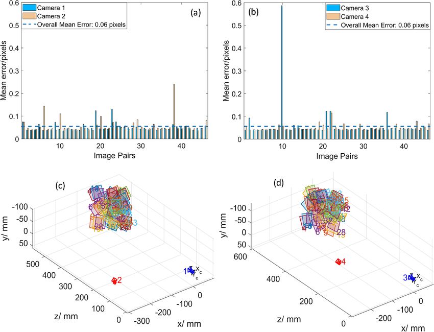
Meas. Sci. Technol. 32 (2021) 045006                                                                                           A Shaheen et al

 Figure 4. Mean reprojection error per image for the camera characterisation. (a) Camera 1, (b) camera 2, (c) camera 3 and (d) camera 4.

Figure 5. Reprojection error per image for stereo-camera pairs (a) stereo-camera pair 1, (b) stereo-camera pair 2, and (c) extrinsic
parameter visualisation of stereo-camera pair 1. The region with coloured squares corresponds to the checkerboard patterns detected by the
stereo-camera pair 1, and (d) extrinsic parameter visualisation of stereo-camera pair 2.

                                                                      6
Meas. Sci. Technol. 32 (2021) 045006                                                                                         A Shaheen et al

Figure 6. Images of a complex shaped object (110 mm × 110 mm × 50 mm) with fringes projected. The images are captured by two
cameras in a stereo configuration (a) Camera-1 and (b) Camera-2. Filtered unwrapped phase maps of the object for (c) data shown in (a) and
(d) data shown in (b).

Figure 7. Rectified unwrapped phase maps. (a) Rectified phase image for the phase map in figures 6(c) and (b) rectified phase image for the
phase map in figure 6(d).

3.3. Three-dimensional reconstruction results                            figures 8(a) and (b)), a dense point cloud is retrieved, as shown
                                                                         in figure 8(c).
We validated the proposed method by implementing the char-                   We determined the point-to-point distance of the two-point
acterisation method on the multi-view fringe projection sys-             clouds in the overlapping region between them using the C2C
tem and acquiring the 3D reconstruction results for a complex            (Cloud-to-Cloud) plugin in CloudCompare [49], where C2C
shaped object (110 mm × 110 mm × 50 mm, Nylon-12). Fol-                  indicates that the distances are determined between a point
lowing the steps in section 2 and using the stereo matching              cloud regarded as a reference and a target point cloud [50].
of the rectified unwrapped phase maps, the 3D reconstruc-                A small region-of-interest (ROI) is chosen between the point
tion results for the complex artefact were acquired, shown               clouds from two sets of stereo-camera pairs, and a comparison
in figures 8(a)–(c). The point clouds from two views are in              of the point cloud from stereo-pair 1 (reference point cloud)
the global coordinate system, and do not require any fur-                was made against the other stereo-pair 2 (target point cloud),
ther registration. By combining the point clouds (shown in               shown in figure 9. Based on the least-squares fitting methods

                                                                     7
Meas. Sci. Technol. 32 (2021) 045006                                                                                              A Shaheen et al

Figure 8. 3D reconstruction results for a complex artefact (110 mm × 110 mm × 50 mm). On the left side, two point clouds acquired from
stereo-camera (a) pair 1, (b) pair 2, respectively, and on the right side, (c) a consolidated point cloud after combining the two views (a)
and (b).

in CloudCompare [49] which relies on nearest-neighbour dis-                specification, the CMM has a volumetric length measure-
tances, the distribution of the distance deviations is shown in            ment accuracy E0 = (1.7 + 3 L/1000) µm (L is the length of
figures 9(b) and (c). The colour map corresponds to the Euc-               the measured object in millimetres) and maximum permiss-
lidean distance between each point in the reference point cloud            ible probing error PFTU = 1.7 µm. The features compared with
(stereo-camera pair 1) and its closest point located in the com-           CMM (four repeat measurements) are shown in figure 10 and
pared point cloud (stereo-camera pair 2). The statistics for the           listed in table 1. The value after the ± sign in table 1 is the
pairs are shown in figure 9(c). The standard deviation of the              standard deviation of the repeat measurements. Each meas-
ROI of the two point clouds is 24 µm which indicates that the              urement from the multi-view system has three repeats. Com-
point clouds acquired from two orthogonal perspectives are in              mercial software (GOM Inspect [53]) was used for inspection
the global frame.                                                          of the 3D reconstruction results acquired from the multi-view
    The structured pattern and waviness seen in figures 9(a)               fringe projection system (shown in figure 8).
and (b) are associated with systematic effects (offsets in the                 Table 1 shows the deviation of the specific features meas-
intrinsic and extrinsic parameters which exhibits complex dis-             ured by the multi-view fringe projection system and compared
tortions in the triangulated point clouds) in the measurement              them with CMM data. From the table, we can see a deviation
process, noise in the phase maps and the accuracy of the sys-              between the multi-view fringe projection data and that from
tem characterisation. These deviations may be considered as                the CMM between 19 and 131 µm. The influence factors caus-
a combined effect of projector’s non-linear gamma effects (in              ing the deviations between the features of interest in (table 1)
case the system is not perfectly characterised), non-linear off-           can be summarised as follows. Firstly, the scanned data from
sets between the DSLR cameras (as four cameras were used),                 the multi-view system contains information only on the two
vibration due to the mechanical shutter of DSLRs, and the                  visible sides. Generally, in a stereo-camera system, the origin
camera’s internal sensor noise.                                            is at the optical centre of camera-1 and the 3D reconstructed
    A Mitutoyo Crysta Apex S7106 CMM (available at the                     points are generated with the origin at the optical centre of
University of Nottingham) was used to perform the dimen-                   camera-1. In our multi-view fringe projection system, camera-
sional measurements which are used as a reference [51]. Spe-               1 and camera-3 are considered as the origin for stereo-camera
cific features were measured using the CMM (21 mm long,                    pair 1 and stereo-camera pair 2, respectively and 3D recon-
3 mm diameter ball-tipped stylus with SP25 Probe, Φ4 mm ×                  structions are made accordingly. Secondly, the other two sides
50 mm) according to the National Physical Laboratory (NPL)                 have voids that affect the comparison analysis. This limitation
good practice guide No. 41 [52]. As per the manufacturer                   can be overcome by adding two more stereo-camera pairs in

                                                                       8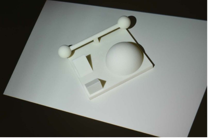
Meas. Sci. Technol. 32 (2021) 045006                                                                                           A Shaheen et al

Figure 9. Results for the deviation of two point clouds for the complex artefact. (a) Point cloud showing the ROI as a red box, (b) a colour
map indicating the point-to-point distance of the two point clouds from stereo-camera pairs 1 and 2, where C2C (Cloud-to-Cloud) depicts
that the distances are determined between a reference point cloud (stereo-camera pair 1) and a target point cloud (stereo-camera pair 2) [50],
and (c) a histogram depicting the statistics of the point-to-point distance of the two point clouds shown in (b), the standard deviation
(St.Dev) of the distribution is 24 µm.

                                        Table 1. Dimensional measurements of the complex artefact.

                                                                                                                  Deviation of multi-view
Feature measured                       CMM measurement                       Multi-view measurement               data from CMM

Sphere-1 diameter                       (22.462 ± 0.011) mm                   (22.580 ± 0.007) mm                 (0.118 ± 0.013) mm
Sphere-2 diameter                       (22.367 ± 0.014) mm                   (22.386 ± 0.001) mm                 (0.019 ± 0.014) mm
Sphere-1 to sphere-2                   (112.447 ± 0.010) mm                  (112.534 ± 0.005) mm                 (0.087 ± 0.011) mm
centre distance
Hemisphere diameter                     (60.194 ± 0.173) mm                   (60.063 ± 0.003) mm                 (0.131 ± 0.173) mm
Wedge-1 inclination                     (44.964 ± 0.017)◦                     (45.052 ± 0.004)◦                   (0.088 ± 0.018)◦
Wedge-2 inclination                    (135.191 ± 0.018)◦                    (135.317 ± 0.003)◦                   (0.126 ± 0.018)◦

                                                                          table 1. The above mentioned factors contribute towards the
                                                                          larger deviation of sphere-1.
                                                                             The multi-view stereo-camera fringe projection system
                                                                          provides higher point densities and addresses the issues of
                                                                          occlusions and shadowing effects with the object, which are
                                                                          typically seen in a single view fringe projection systems. The
                                                                          reconstructed point clouds from multiple perspectives are in
                                                                          the same coordinate system and do not depend on point cloud
                                                                          course/fine registration methods. The point cloud in figure 8(c)
                                                                          contains more information and have a higher number of data
                                                                          points compared to the acquisition from a single-view, as
                                                                          shown in figures 8(a) and (b). The point-to-point distances
                                                                          for a small ROI between the two-point clouds of the meas-
                                                                          ured object is around 24 µm (see figures 9(a)–(c)) which will
                                                                          further be optimised in the future work to achieve a higher
Figure 10. Photograph of the complex artefact with labelled               accuracy of the system characterisation. The future work will
features measured by CMM. The results are shown in table 1.
                                                                          focus on introducing more robust optical components (high-
                                                                          speed machine vision cameras and projectors with high frame
the other two quadrants. Essentially, one stereo-camera pair is           rates), investigating the dependence of the structured pattern
needed in each quadrant to reconstruct the full form. Thirdly,            on the system characterisation accuracy and the correspond-
the systematic errors causing the waviness and structured pat-            ence method, and incorporating the information rich met-
tern shown in figures 9(a) and (b) contribute to the deviation            rology (IRM) to make it smart optical form measurement
of the measured features from the CMM data as shown in                    system.

                                                                      9
Meas. Sci. Technol. 32 (2021) 045006 A Shaheen et al
Figure 11. Conventional method. (a) Photograph of the multi-view fringe projector system with two cameras and projectors considered for
the conventional approach, (b) schematic diagram of the characterisation of the multi-view fringe projection system.
Figure 12. Mean reprojection error per image for the camera characterisation. (a) Camera 1, (b) camera 2, (c) projector 1 and (d) projector 2.
Table 2. Dimensional measurements of a hemisphere shaped AM artefact. Each measurement has three repeats. The hemisphere height
measured by CMM (four repeat measurements) is (9.6830 ± 0.0004) mm.
Hemisphere height Multi-view Deviation of multi-view data
(Ref: top plane of the base) measurement (mm) from CMM data (mm)
Proposed method (9.671 ± 0.009) (0.012 ± 0.009)
Conventional method (9.549 ± 0.015) (0.134 ± 0.015)
4. Comparison with the conventional method characterising a multi-view fringe projection system relies
on capturing several positions of a standard checkerboard
We compared our proposed method with a conventional (checker width is 4 mm) in the measurement volume and
method. The multi-view fringe projection system consists determining the intrinsic parameters of the cameras [54]. The
of two projectors (DLPC300 Texas Instruments) and two projector is incapable of capturing images, therefore, the cam-
cameras (Nikon D3500, 4496 × 3000 pixels), the arrange- era captures the images for the projector and the one-to-one
ment is shown in figure 11(a). The conventional method of correspondences between the camera and the projector image
10Meas. Sci. Technol. 32 (2021) 045006 A Shaheen et al
Figure 13. 3D reconstruction results of a hemisphere shaped AM artefact 60 mm × 60 mm × 20 mm. Top row: conventional method (a)–(b)
Point clouds acquired from camera-projector pair 1 and 2 respectively, (c) combined point cloud of the data shown in (a)–(b). Bottom row:
proposed method. (d)–(e) Point clouds from two sets of stereo-camera pairs and (f) the combination of two point clouds shown in (d)–(e).
pixel coordinates are determined using a phase-stepped fringe The coordinates of the checkerboard corners were detec-
projection method. The absolute phase is obtained through ted using a developed image processing algorithm [31]. The
temporal phase unwrapping that utilises a combined phase- intrinsic and extrinsic parameters of all the cameras were
stepped and binary coded method [26, 41]. The retrieved phase determined based on a pinhole camera model as explained
maps are used to determine the extrinsic parameters and the in section 2 (Step A—camera characterisation). The absolute
global frame of reference. phase maps are used to find the one-to-one correspondence
Following the pipeline shown in figure 11(b), a set of hori- between the camera and projector intensity pixels and to estim-
zontal and vertical phase-stepped fringe patterns are projec- ate the projector parameters. Figure 12 shows the reprojection
ted onto the checkerboard and images are captured at dif- errors for the cameras and projectors. The mean reprojection
ferent positions. The checkerboard was moved manually in error per image for the cameras is 0.04 pixels, however, the
the measurement volume. By incorporating the absolute phase error in the projector characterisation is around 0.20 pixels.
maps, the projector coordinates are determined from the cam- The accuracy of the system characterisation is highly depend-
era coordinates using the one-to-one correspondence estab- ent on the characterisation of the individual optical compon-
lished through the phase maps [23–26]. The transformation ents (cameras and projectors) and has a significant influence
relation can be represented as: on the system performance.
( ) Each camera and projector is regarded as a stereo pair and
P the transformation relationship is given by:
up = ϕh (uc , vc ) , (6)
2π
Sc Ic = Ac [Rc , Tc ]Xw , (8)
( )
P
vp = ϕv (uc , vc ) , (7)
2π
where (up , vp ) are the image coordinates of the projector, Sp Pp = Ap [Rp , Tp ]Xw , (9)
(uc , vc ) are the camera image coordinates, (ϕh , ϕv ) are the hori-
zontal and vertical phase values captured by the camera, and P where X w is the homogeneous point coordinate in the world
is the number of pixels per fringe period (called fringe pitch). coordinate system, (I c , I p ) are the homogeneous coordinates of
11Meas. Sci. Technol. 32 (2021) 045006 A Shaheen et al
Figure 14. Results for the deviation of two point clouds of a hemisphere shaped AM artefact. Top row: conventional method. (a) Point
cloud showing the ROI as a red box, (b) colour map indicating the point-to-point distance of the two point clouds from camera-projector
pairs 1 and 2, where C2C (Cloud-to-Cloud) depicts that the distances are determined between a reference point cloud (stereo-camera pair 1)
and a target point cloud (stereo-camera pair 2) [50] and (c) histogram depicting the statistics of the point-to-point distance of the two point
clouds shown in (b). Bottom row: proposed method. (d) ROI shown as a red box, (e) point-to-point distance between the two point clouds
from stereo-pair 1 and 2 and (f) statistical distribution of the data shown in (e).
the image point in the image coordinate system, (Ac , Ap ) cor- The global frame is defined by taking a plane in the
respond to the intrinsic matrices, (Rc , Rp ) and (Tc , Tp ) are the common field of view of all the cameras and projectors.
rotational and translational matrices for the camera and pro- The world coordinates between each camera–projector
jector, respectively. pair are established by triangulation and given as,
c −1 c c
x h11 − uc hc31 hc12 − uc hc32 c
h13 − uc hc33 u h34 − hc14
y = h21
c
− vc hc31 hc22 − vc hc32 hc23 − vc hc33 vc hc34 − hc24 , (10)
z h11 − up hp31
p
hp12 − up hp32 hp13 − up hp33 up hp34 − hp14
where (x, y, z) are the world coordinates, (uc , vc ) are the camera artefact. The top row (figures 13(a)–(c)) depicts the res-
image coordinates and up is the projector image coordinate, ults for the conventional method acquired using two sets of
hij (i = 1, 2, 3 and j = 1, 2, 3, 4) are the elements of the homo- cameras and projectors. The correspondences between each
graphy matrices for the camera and projector [54]. camera–projector pair are established based on the triangula-
Using the triangulation principle (equation (10)), the cor- tion principle, and the outcome is two separate point clouds
respondences between each camera-projector pair are gen- from orthogonal perspectives. Figure 13(c) corresponds to the
erated and 3D point clouds are acquired. Figures 13 shows combined point cloud of figures 13(a) and (b) based on the
the 3D reconstructions results of a hemisphere shaped AM conventional approach. The bottom row (figures 13(d)–(f))
12Meas. Sci. Technol. 32 (2021) 045006 A Shaheen et al
shows the results of the same hemisphere shaped AM arte- Acknowledgments
fact but 3D surface reconstruction is achieved based on the
stereo rectification approach (explained in sections 2 and 3). This research was funded by The EU Framework Programme
The CMM measurements (four repeats) and the deviations of for Research and Innovation—Horizon 2020—Grant Agree-
the multi-view results from the CMM are listed in table 2. ment No. 721383 within the PAM2 (Precision Additive Metal
In contrast to the proposed method, the hemisphere height Manufacturing) research project and by the Engineering and
measurement has larger deviations (134 µm) for the conven- Physical Sciences Research Council [EPSRC Grant Nos.
tional method (table 2). EP/M008983/1, EP/L016567/1]. The authors would like to
In order to evaluate the effectiveness of the two approaches, thank Dr Mohammed Isa (University of Nottingham) for
a small ROI was chosen in the overlapping region between providing help with the CMM measurements.
the two point clouds. The point-to-point distances are determ-
ined and shown as a deviation map in figure 14(b) for the con- Conflicts of interest
ventional method and figure 14(e) for the proposed approach.
The statistical distributions of the deviation map are depic- The authors declare no conflicts of interest.
ted in figures 14(c) and (f) for the conventional and the
proposed approaches, respectively. The conventional method
has a mean value of 293 µm and a standard deviation of ORCID iD
181 µm. The conventional method struggles with mapping
errors; the point clouds comprise more noise and require fur- A Shaheen https://orcid.org/0000-0003-0277-9305
ther registration using iterative-closest-point and fine regis-
tration algorithms. However, with our proposed method, the References
mean (figure 14(f)) is 58 µm and the deviation for the overlap-
ping ROI is 20 µm. [1] Liu Y, Blunt L, Zhang Z, Rahman H A, Gao F and Jiang X
2020 In-situ areal inspection of powder bed for electron
beam fusion system based on fringe projection profilometry
Addit. Manuf. 31 100940
5. Conclusions
[2] Wu Y, Dantanarayana H G, Yue H and Huntley J M 2017
Accurate characterisation of hole geometries by fringe
In this paper, a novel characterisation approach for a multi- projection profilometry Videometrics, Range Imaging and
view fringe projection system has been presented. The method Applications XIV vol 10332 (Bellingham, WA: Int. Society
relies on finding the correspondences between the rectified for Optics and Photonics) p 1033204
unwrapped stereo phase maps, and the matched phase values [3] Jiang C, Jia S, Xu Y, Bao Q, Dong J and Lian Q 2015 The
application of multi-frequency fringe projection
between the stereo phase images are triangulated to acquire 3D profilometry on the measurement of biological tissues
form. In contrast to the existing methods for determining the Biomed. Mater. Eng. 26 S395–S403
correspondences between the camera and projector in multi- [4] Lin C-H, He H-T, Guo H-W, Chen M-Y, Shi X and Yu T 2005
view fringe projection systems, the benefit of this method is Fringe projection measurement system in reverse
that it does not depend on the projector’s characterisation (does engineering J. Shanghai Univ. 9 153–8
[5] Kuş A 2009 Implementation of 3d optical scanning technology
not require multiple characterisations) as the stereo cameras for automotive applications Sensors 9 1967–79
would have the same phase value for the same point, irrespect- [6] Xia R, Zhao J, Zhang T, Su R, Chen Y and Fu S 2020
ive of the projector. However, the effectiveness of this method Detection method of manufacturing defects on aircraft
is highly depended on the system’s characterisation, and any surface based on fringe projection Optik 164332
offset in the stereo-camera pairs will affect the robustness of [7] Leach R, Bourell D, Carmignato S, Donmez A, Senin N and
Dewulf W 2019 Geometrical metrology for metal additive
the method. manufacturing CIRP Ann. 68 677–700
The characterisation method has been implemented, and [8] Abedi F, Yang Y and Liu Q 2018 Group geometric calibration
the system has been used for the form measurement of com- and rectification for circular multi-camera imaging system
plex AM artefacts. The 3D reconstruction results from mul- Opt. Express 26 30596–613
tiple perspectives are effectively in a global frame and do [9] Liu Z, Meng Z, Gao N and Zhang Z 2019 Calibration of the
relative orientation between multiple depth cameras based
not require further registration. Furthermore, the reconstruc- on a three-dimensional target Sensors 19 3008
ted results have addressed some of the limitations of a single [10] Sun J, He H and Zeng D 2016 Global calibration of multiple
view system, primarily associated with occlusions, shadowing cameras based on sphere targets Sensors 16 77
and high slope angles. We also compared the proposed method [11] Feng M, Jia X, Wang J, Feng S and Zheng T 2017 Global
with a conventional method and achieved improved perform- calibration of multi-cameras based on refractive projection
and ray tracing Sensors 17 2494
ance. The future work will focus on introducing machine [12] Tsai R Y 1986 An efficient and accurate camera calibration
vision cameras, and to investigate the relationship of the technique for 3D machine vision Proc. Comp. Vis. Pattern
structured deviations with the characterisation accuracy and Recognit. 364–74
the proposed correspondence method. This investigation will [13] Zhang Z 2000 A flexible new technique for camera calibration
help to address the current issues with the DSLR’s camera IEEE Trans. Pattern Anal. Mach. Intell. 22 1330–4
[14] Zhang S and Huang P S 2006 Novel method for structured
(camera’s internal sensor noise, vibration due to mechanical light system calibration Opt. Eng., Bellingham 45 083601
shutter), and to achieve improved accuracy of the extrinsic [15] Huang Z, Xi J, Yu Y and Guo Q 2015 Accurate projector
properties of the stereo-camera pairs. calibration based on a new point-to-point mapping
13Meas. Sci. Technol. 32 (2021) 045006 A Shaheen et al
relationship between the camera and projector images Appl. [33] Brown M Z, Burschka D and Hager G D 2003 Advances in
Opt. 54 347–56 computational stereo IEEE Trans. Pattern Anal. Mach.
[16] Albers O, Poesch A and Reithmeier E 2015 Flexible Intell. 25 993–1008
calibration and measurement strategy for a multi-sensor [34] Hirschmuller H 2007 Stereo processing by semiglobal
fringe projection unit Opt. Express 23 29592–607 matching and mutual information IEEE Trans. Pattern
[17] Gai S, Da F and Tang M 2019 A flexible multi-view Anal. Mach. Intell. 30 328–41
calibration and 3D measurement method based [35] Shimizu M and Okutomi M 2008 Calibration and rectification
on digital fringe projection Meas. Sci. Technol. for reflection stereo 2008 Conf. Computer Vision and
30 025203 Pattern Recognition (IEEE) pp 1–8
[18] Gdeisat M, Qudeisat M, AlSa M, Burton D, Lilley F and [36] Tsai R 1987 A versatile camera calibration technique for
Ammous M M et al 2016 Simple and accurate empirical high-accuracy 3D machine vision metrology using
absolute volume calibration of a multi-sensor fringe off-the-shelf TV cameras and lenses IEEE J. Robot. Autom.
projection system Opt. Lasers Eng. 80 32–44 3 323–44
[19] Deetjen M E and Lentink D 2018 Automated calibration of [37] Zhang Z 1999 Flexible camera calibration by viewing a plane
multi-camera-projector structured light systems for from unknown orientations Proc. 7th IEEE Int. Conf.
volumetric high-speed 3D surface reconstructions Opt. Computer Vision vol 1 (IEEE) pp 666–73
Express 26 33278–304 [38] Gühring J 2000 Dense 3D surface acquisition by structured
[20] Servin M, Padilla M, Garnica G and Gonzalez A 2016 light using off-the-shelf components Videometrics and
Profilometry of three-dimensional discontinuous solids by Optical Methods for 3D Shape Measurement vol
combining two-steps temporal phase unwrapping, 4309 (Bellingham, WA: Int. Society for Optics and
co-phased profilometry and phase-shifting interferometry Photonics) pp 220–31
Opt. Lasers Eng. 87 75–82 [39] Yang R, Cheng S and Chen Y 2008 Flexible and accurate
[21] Servin M, Garnica G, Estrada J and Quiroga A 2013 Coherent implementation of a binocular structured light system Opt.
digital demodulation of single-camera n-projections for Lasers Eng. 46 373–9
3D-object shape measurement: co-phased profilometry Opt. [40] Bradski G and Kaehler A 2008 Learning Opencv: Computer
Express 21 24873–8 Vision with the Opencv Library (Sebastopol, CA: O’Reilly
[22] Servin M, Garnica G and Padilla J 2014 Co-phased 360-degree Media, Inc.)
profilometry of discontinuous solids with 2-projectors and [41] Chen X, Chen S, Luo J, Ma M, Wang Y, Wang Y and Chen L
1-camera Latin America Optics and Conf. (Optical Society 2017 Modified gray-level coding method for absolute phase
of America) p LTh2B–2 retrieval Sensors 17 2383
[23] Xiao S, Tao W, Yan H and Zhao H 2014 A new geometrical [42] He X and Kemao Q 2020 A comparison of n-ary simple code
model and mathematical method for three-dimensional and n-ary gray code phase unwrapping in high-speed fringe
surface reconstruction based on phase-shifting structured projection profilometry Opt. Lasers Eng. 128 106046
light technique Optical Metrology and Inspection for [43] Herráez M A, Burton D R, Lalor M J and Gdeisat M A 2002
Industrial Applications III vol 9276 (Bellingham, WA: Int. Fast two-dimensional phase-unwrapping algorithm based
Society for Optics and Photonics) p 92761Z on sorting by reliability following a noncontinuous path
[24] Lu P, Sun C, Liu B and Wang P 2017 Accurate and robust Appl. Opt. 41 7437–44
calibration method based on pattern geometric [44] Zuo C, Huang L, Zhang M, Chen Q and Asundi A 2016
constraints for fringe projection profilometry Appl. Opt. Temporal phase unwrapping algorithms for fringe
56 784–94 projection profilometry: a comparative review Opt. Lasers
[25] Zhang C, Zhao H and Jiang K 2016 Fringe-period selection for Eng. 85 84–103
a multifrequency fringe-projection phase unwrapping [45] Saldner H O and Huntley J M 1997 Temporal phase
method Meas. Sci. Technol. 27 085204 unwrapping: application to surface profiling of
[26] Sansoni G, Carocci M and Rodella R 1999 Three-dimensional discontinuous objects Appl. Opt. 36 2770–5
vision based on a combination of gray-code and phase-shift [46] Scharstein D and Szeliski R 2002 A taxonomy and evaluation
light projection: analysis and compensation of the of dense two-frame stereo correspondence algorithms Int. J.
systematic errors Appl. Opt. 38 6565–73 Comput. Vis. 47 7–42
[27] Jang W, Je C, Seo Y and Lee S W 2013 Structured-light [47] Zisserman A and Hartley R 2000 Multiple View Geometry in
stereo: comparative analysis and integration of Computer Vision (Cambridge: Cambridge University Press)
structured-light and active stereo for measuring dynamic [48] Bointon P, Todhunter L, Stavroulakis P, Clare A and Leach R
shape Opt. Lasers Eng. 51 1255–64 2018 The effects of vibration on fringe projection systems
[28] Park M-G, Park J, Shin Y, Lim E-G and Yoon K-J 2015 Stereo Proc. 18th Int. Conf. pp 119–20
vision with image-guided structured-light pattern matching [49] CloudCompare 2020 (version 2.11.1) [GPL Software]
Electron. Lett. 51 238–9 (available at: www.cloudcompare.org/)
[29] Liu K, Zhou C, Wei S, Wang S, Fan X and Ma J 2014 [50] Lague D, Brodu N and Leroux J 2013 Accurate 3D
Optimized stereo matching in binocular three-dimensional comparison of complex topography with terrestrial laser
measurement system using structured light Appl. Opt. scanner: application to the Rangitikei Canyon (NZ) ISPRS
53 6083–90 J. Photogramm. Remote Sens. 82 10–26
[30] Scharstein D and Szeliski R 2003 High-accuracy stereo depth [51] Mitutoyo Crysta Apex: S7106 CMM (available at:
maps using structured light 2003 IEEE Proc. Computer www.mitutoyo.co.uk.)
Conf. Computer Vision and Pattern Recognition vol [52] Flack D 2014 NPL good practice guide no. 41 CMM
1 (IEEE) p I–I measurement strategies
[31] Bouguet J 2001 Camera Calibration Toolbox for Matlab [53] GOM—Precise Industrial 3D Metrology (available at:
(Pasadena, CA: Computational Vision Group, California https://www.gom.com/)
Institute of Technology) [54] Shaheen A, Sims-Waterhouse D, Bointon P, Piano S and Leach
[32] Shih S-E and Tsai W-H 2013 A two-omni-camera stereo R 2019 Automated characterisation of multi-view fringe
vision system with an automatic adaptation capability to projection system for three-dimensional measurement of
any system setup for 3-d vision applications IEEE Trans. additively manufactured parts Proc. Euspen/ASPE
Circuits Syst. Video Technol. 23 1156–69 Advancing Precision in Additive Manufacturing p 19–22
14You can also read