Characterization of Passive Intermodulation Distortion in MultiBand FDD Radio Systems
←
→
Page content transcription
If your browser does not render page correctly, please read the page content below
DEGREE PROJECT IN INFORMATION AND COMMUNICATION
TECHNOLOGY,
SECOND CYCLE, 30 CREDITS
STOCKHOLM, SWEDEN 2019

Characterization of Passive
Intermodulation Distortion in
MultiBand FDD Radio Systems

TOMÁS SOARES DA COSTA

KTH ROYAL INSTITUTE OF TECHNOLOGY
SCHOOL OF ELECTRICAL ENGINEERING AND COMPUTER SCIENCE
Characterization of Passive Intermodulation
Distortion in MultiBand FDD Radio Systems

             TOMÁS SOARES DA COSTA

              Stockholm September, 2019

                Communication Systems
  School of Electrical Engineering and Computer Science
              Kungliga Tekniska Högskolan

Supervisors:
Adnan Kiayani, Ph.D.
Department of Algorithm System Design,
Ericsson AB
Stockholm, Sweden

Claes Beckman, Ph.D., Professor
Department of Wireless Communications,
Kungliga Tekniska Högskolan
Stockholm, Sweden

Examiner:
Slimane Ben, Ph.D., Professor
Department of Wireless Communications,
Kungliga Tekniska Högskolan
Stockholm, Sweden

Opposition:
João Torres,
Information and Communication Technology,
Kungliga Tekniska Högskolan
Stockholm, Sweden
Abstract

Intermodulation distortion (IMD) is a phenomenon that results in generation of spurious
distortion signals when two or more signals of different frequencies pass through a nonlin-
ear system. In general, IMD occurs in active circuits of a radio system, however, passive
wireless components such as filters, transmission lines, connectors, antennas, attenuators
etc., can also generate IMD particularly when transmit power is very high. The IMD
in the latter case is referred to as passive intermodulation (PIM) distortion. With the
continuing advancement of radio system coupled with the radio spectrum scarcity, PIM
interference is recognized as a potential obstacle to achieving the full capacity of a radio
network.

The assiduous enhancement of radio systems for faster data speeds and higher capacity
further exacerbate the PIM interference problem. Features like carrier aggregation (CA)
and multiple input multiple output (MIMO) make the PIM a more problematic issue. In
modern co-sites, radio systems are often coupled together, operating in multiple bands.
Furthermore, in frequency division duplex (FDD) systems, transmitter (Tx) and receiver
(Rx) operate simultaneously. In such scenarios, PIM is likely to occur in the signal’s
path and may potentially hit multiple Rx bands causing undesired interference.

The PIM sources in the BS radio systems can be divided into two groups, namely
internal and external. Internal sources are the passive components within the radio such
as filters, transmission lines, connectors, antennas, etc. External sources, on the other
hand, are the passive elements beyond the BS antenna but within the RF signal path
such as metallic and rusty objects in antenna near field. For both types of sources,
the high power current flowing through such passive objects can prompt a nonlinear
behavior that in turn generates IMD.

This thesis addresses PIM distortion in multiband BS radio systems by devising a charac-
terization. For this purpose, the research begins by establishing a mathematical model
for IMD and reviewing the physics that prompt nonlinear behavior in these sources.
Afterwards, the enhancements in radio systems that enlarge the bandwidths and ex-
acerbate PIM are discussed. In particular, how IMD is worsen in broadband radios is

                                            iii
Abstract iv highlighted, and to complement this discussion, a review of PIM mitigation techniques is also presented. In the final part of this work, extensive lab measurement results are presented where effects of PIM with external PIM sources are analyzed and discussed. Overall, this thesis helps to build a better understanding of PIM interference problem in radio systems by providing useful insights into the nonlinear mechanisms in passive components causing PIM.
Abstrakt

Harmonisk distorsion eller ”Intermodulationsdistorsion” (IMD) är ett fenomen som
resulterar i generering av falska signaler när två eller flera radiosignaler med olika
frekvenser blandas när de passerar genom ett olinjärt system. I allmänhet förekommer
IMD i aktiva kretsar i ett radiosystem. Emellertid, passiva trådlösa komponenter såsom
filter, transmissionsledningar, kontakter, antenner, dämpare etc., kan också generera
IMD, särskilt när sändningseffekten är mycket hög. IMD i det senare fallet kallas ”pas-
siv intermodulationsdistorsion” (PIM). De senaste årens utveckling av mer avancerade
radiosystem, i kombination med radiospektrumbrist, har inneburit att PIM idag ses
som ett av de största potentiella hindren för att uppnå den fulla kapaciteten i tex 5G
radionätverk.

Den ständiga utvecklingen av de cellulära radiosystemen mot högre datahastigheter och
högre kapacitet förvärrar ytterligare PIM-störningsproblemet: Funktioner som bärvågs
aggregering (carrier aggregation, CA) och ”multiple input multiple output” (MIMO)
system gör PIM till ett ännu större problem. I moderna samarbetsplatser, radiosystem
är ofta kopplade ihop och fungerar i flera band.

I system med frekvensduplex (FDD-system), där sändare (Tx) och mottagare (Rx) ar-
betar samtidigt men på skilda frekvenser, kan PIM med hög sannolikhet inträffa i sig-
nalenvägen och dess distortionsprodukter potentiellt träffa flera Rx-band och därmed
orsakar oönskad störning.

PIM-källorna i Basstationssystemen kan delas in i två grupper: interna och externa.
Interna källor är passiva komponenter inne i radion såsom filter, transmissionslinjer,
kontakter, antenner etc. Externa källor å andra sidan är de passiva elementen bortom
Basstations-antennen men inom RF-signalvägen såsom metalliska och rostiga föremål i
antennen närfält. För båda typerna av källor är det den höga effekttätheten som får
sådana passiva objekt att uppvisa ett elektriskt olinjär beteende som i sin tur genererar
IMD.

                                             v
Abstrakt vi Denna avhandling behandlar PIM-distorsion i basstationssystem för multipla frekvens- band genom att utforma en karaktärisering av de genererade signalerna. För detta ändamål börjar studien med att skapa en matematisk modell för IMD och sedan granska fysiken som skapar det olinjära beteendet i olika PIM-källor. Därefter diskuteras hur PIM genereras i bredbandiga radiosystem. I synnerhet diskuteras hur IMD förvärras i bredbandiga radiosystem samtidigt som en översikt av metoder att motverka dess effekter på prestandan presenteras. I den första delen av denna rapport presenteras resultat från omfattande laborato- riemätningar, där effekterna av PIM med externa PIM-källor analyseras och diskuteras. Sammantaget bidrar denna avhandling till att bygga en bättre förståelse av PIM-störningsproblem i radiosystem genom att tillhandahålla användbar insikter om passiva icke-linjära mekanis- mer i komponenter som orsakar PIM.
Acknowledgments

The research work reported in this thesis was carried out during the year 2019 at the
Department of Algorithm System Design, Ericsson AB, Stockhom, and Department of
Wireless Communications, Kungliga Tekniska Högskolan (KTH), Stockholm, Sweden.

Foremost, I would like to express my sincere gratitude to my two supervisors Dr. Adnan
Kiayani and Prof. Claes Beckman, who guided and helped me during the research of this
thesis. I am deeply grateful to Dr. Adnan Kiayani for giving me the opportunity to work
under his supervision during my time in Ericsson. His guidance and feedback instigated
in me work ethic, perfectionism and professional values that will support the remainder
of my careers. I am also grateful to my supervisor at KTH, Prof. Claes Beckman, for the
assiduous feedback and guidance. His tremendous amount of knowledge on the subject
and positive attitude gave me the curiosity to further investigate the problem and were
crucial during the research.

This thesis was financially supported by Ericsson AB, Sweden. Hence, I would like to
express my appreciation to the company itself, the HR department for handling practical
matters efficiently and everyone at the department of Algorithm System Design for
creating such an inspiring work environment. In particular, I would like to express my
gratitude to this department leader, Spendim Dalipi for giving me the opportunity to
work in Ericsson, and for being a great person to work for.

I would like to thank my beloved friends in Portugal Pedro Croca, Pedro Martins, Ruben,
Carlos, Nuno, Sebastiao, etc. for the experiences in the past five years. Without their
constant support, motivation and company, this achievement would be nothing short
than impossible. Also, I would like to extend the compliments to my peers, namely my
friends João Torres and Mariana Filipe, who accompanied me during my time in Sweden
and, with whom I had the pleasure to work throughout the academic year. Lastly, I
would like to thanks the faculties and professors of both IST and KTH and, in particular,
Prof. José Santa Rita for being my mentor and teaching me how to think.

                                           vii
Acknowledgments viii I would like to extend my thanks to my beloved family as I would not be the person I am if not for them. Thanks my grandparents Rui, Dina, Fernando and Madalena, my cousins André, Teresa and Miguel, and aunt Margarida. Thanks to my dad, Pedro, thanks for inspiring me to become a engineer as well, for teaching me how to laugh and play sports, and for attending every event I ever participated, since the first day of school to the last soccer game. Thanks to my younger brother Martim, thanks for every fight, argument, game, holiday, birthday, moment I got to share with you, hopefully I will be able to repay your affection by becoming a great role model for you to follow and by help you with your endeavors. Lastly my thanks to my wonderful mother, Carla. You are my inspiration, and everything I ever accomplish or become is because of you. Finally I would like to dedicate this work to the memory of my late aunt and uncle, Eugénia and Acácio Barreiros, who, unfortunately, will not be with me when I graduate. They were truly incredible persons whose memory I will forever cherish. Stockholm, August 2019 Tomás Soares da Costa
Contents

Abstract                                                                                             iii

Abstrakt                                                                                              v

Acknowledgments                                                                                      vii

Contents                                                                                             ix

Abbreviations                                                                                        xi

1 Introduction                                                                                        1
  1.1 Background and Motivation . . . . . . . . . . . . . . . . . . . . . . . . . .                   1
  1.2 Scope and Contributions of the Thesis . . . . . . . . . . . . . . . . . . . .                   3
  1.3 Thesis Outline . . . . . . . . . . . . . . . . . . . . . . . . . . . . . . . . .                4

2 Fundamentals of Passive Intermodulation                                                             5
  2.1 Intermodulation Distortion . . . . . . . . . . . . . . . . . . . . .       .   .   .   .   .    5
  2.2 Sources of Intermodulation Distortion . . . . . . . . . . . . . . .        .   .   .   .   .    8
      2.2.1 Classification of PIM Sources . . . . . . . . . . . . . . . .        .   .   .   .   .    9
  2.3 Internal PIM sources . . . . . . . . . . . . . . . . . . . . . . . . .     .   .   .   .   .   11
      2.3.1 Contact Nonlinearities . . . . . . . . . . . . . . . . . . . .       .   .   .   .   .   11
             2.3.1.1 Metal-Insulator-Metal situations in a RF system             .   .   .   .   .   12
      2.3.2 Electro-Thermal PIM Sources . . . . . . . . . . . . . . . .          .   .   .   .   .   14
             2.3.2.1 Electro-Thermal Theory . . . . . . . . . . . . . .          .   .   .   .   .   15
             2.3.2.2 Distributed PIM sources . . . . . . . . . . . . .           .   .   .   .   .   16
  2.4 External PIM Sources . . . . . . . . . . . . . . . . . . . . . . . .       .   .   .   .   .   17
      2.4.1 Reflection on Metal Surfaces . . . . . . . . . . . . . . . .         .   .   .   .   .   18
      2.4.2 Dielectric Coating and Wave Polarization . . . . . . . . .           .   .   .   .   .   19
      2.4.3 External Sources as PIM Antennas . . . . . . . . . . . . .           .   .   .   .   .   20
  2.5 Discussion . . . . . . . . . . . . . . . . . . . . . . . . . . . . . . .   .   .   .   .   .   21

                                            ix
Contents x
3 PIM Distortion in Radio Systems 23
3.1 Evolution of Wireless Networks . . . . . . . . . . . . . . . . . . . . . . . . 24
3.1.1 Overview of 3GPP Global System for Mobile Communications . . 24
3.1.2 Overview of 3GPP Long Term Evolution . . . . . . . . . . . . . . 25
3.1.2.1 OFDMA and SC-FDMA Principles . . . . . . . . . . . . 26
3.1.3 Overview of 3GPP Long Term Evolution-Advanced . . . . . . . . . 26
3.1.3.1 Carrier Aggregation Fundamentals . . . . . . . . . . . . . 28
3.1.4 Overview of 3GPP New Radio . . . . . . . . . . . . . . . . . . . . 29
3.1.4.1 NR Physical Layer Principles . . . . . . . . . . . . . . . . 30
3.2 Passive Intermodulation Distortion in Radio Systems . . . . . . . . . . . . 31
3.2.1 Passive Intermodulation in Broadband Radio Systems . . . . . . . 32
3.2.2 Passive Intermodulation Impact on Network Performance and Phys-
ical Layer . . . . . . . . . . . . . . . . . . . . . . . . . . . . . . . . 35
3.3 Passive Intermodulation Mitigation Techniques . . . . . . . . . . . . . . . 36
3.3.1 Physical Mitigation of Passive Intermodulation Interference . . . . 36
3.3.1.1 Guidelines for Mitigation of Internal Sources . . . . . . . 37
3.3.1.2 Guidelines for Mitigation of External Sources . . . . . . . 37
3.3.2 Radio Integrated Mitigation of Passive Intermodulation Interference 38
3.4 Discussion . . . . . . . . . . . . . . . . . . . . . . . . . . . . . . . . . . . . 39
4 Measurements-based Analysis of External Passive Intermodulation 41
4.1 Radio Setup and Use Cases . . . . . . . . . . . . . . . . . . . . . . . . . . 41
4.2 Power Spectral Density Analysis . . . . . . . . . . . . . . . . . . . . . . . 44
4.3 External PIM Analysis for Case Studies . . . . . . . . . . . . . . . . . . . 46
4.4 Digital Cancellation of PIM . . . . . . . . . . . . . . . . . . . . . . . . . . 51
4.5 Discussion . . . . . . . . . . . . . . . . . . . . . . . . . . . . . . . . . . . . 52
5 Conclusion and Future Work 55
Bibliography 59Abbreviations
3GPP 3rd Generation Partnership Project
2G second generation
3G third generation
4G fourth generation
5G fifth generation
BS base station
BSS base station subsystem
Bw bandwidth
CA carrier aggregation
CC component carrier
CDMA code division multiple access
CFO carrier frequency offset
CM cubic metric
CP cyclic prefix
DFT discrete Fourier transform
DL downlink
ET electro-thermal
FDD frequency division duplexing
FDMA frequency division multiple access
GPRS general packet radio service
GSM global system for mobile communications
HD harmonic distortion
ICI intercarrier interference
IDFT inverse discrete Fourier transform
IEEE institute of electrical and electronics engineers
IM intermodulation
IMD intermodulation distortion
IM3 third-order intermodulation distortion product
IMT International Mobile Telecommunications
ISI inter symbol interference
xiAbbreviations xii ITU-R international telecommunication union radio communication sector LS least squares LTE long term evolution LTE-A long term evolution advanced eMBB enhanced mobile broadband mMTC massive machine-type communications MCS metal clamp attached to small support structure MM metal-metal junction MIM metal-insulator-metal MIMO multiple input multiple output MSC mobile-services switching center NTL nonlinear transmission line NR new radio NNS network and switching subsystem OFDM orthogonal frequency division multiplexing OFDMA orthogonal frequency division multiple access OSS operation support subsystem PA power amplifier PAPR peak-to-average power ratio PIM passive intermodulation PIMP passive intermodulation products PHY physical layer PO physical optics PSD power spectral density PSK phase shift keying QAM quadrature amplitude modulation QPSK quadrature phase shift keying RAN radio access network RB resource block RF radio frequency Rx receiver RU radio unit SC-FDMA single carrier frequency division multiple access SER symbol error rate SNR signal-to-noise ratio SINR signal-to-interference plus noise ratio TDPO temperature coefficients of resistance TDPO time domain physical approach TDD time division duplexing
Abbreviations                                                xiii

 TDMA           time division multiple access
 Tx             transmitter
 UE             user equipment
 UL             uplink
 UMTS           universal mobile telecommunications system
 URLLC          ultra-reliable low-latency communications
 WLAN           wireless local area network
 WB             wideband
Chapter 1

Introduction

1.1    Background and Motivation

Radio systems have experienced tremendous growth during the last few decades due to
the ever-increasing demands of higher data rates, low latency, and better wireless con-
nectivity. This is due to the growing data usage in mobile devices for modern services
like multimedia contents, and the growing number of devices. Hence, existing wireless
communication systems are specified to support the data rates within the range of 100
Mbps to 1 Gbps for both uplink (UL) and downlink (DL), depending on the mobility
of the device. Currently, the 3rd Generation Partnership Project (3GPP) has defined
standards for operators to accommodate data rates of 10+ Gbps during the radio trans-
mission under various mobility conditions. In order to achieve even higher data rates,
its required wider bandwidths and better flexibility in data transmission. However,
the available bandwidth in radio-frequency (RF) spectrum is limited and, due to the
numerous wireless services available, it is becoming completely saturated.

Given the restrictions of the spectrum and available technologies at the time of release,
different generations of radio system have different operating strategies to provide in-
creased data rates. Second generation (2G) radio systems, commonly referred as Global
System for Mobile Communications (GSM), make use of narrowband Time Division
Multiple Access (TDMA) techniques to transmit (Tx) signals. This technique increased
the capacity of the radio system compared to the previous first generation (1G) tech-
nology, as it allowed more users to be accommodated within the available transmission
bandwidth. This technology uses 200 kHz wide RF channels and enables up to eight
users to access each carrier, which results in data rates around 270 kbps. The next
enhancement, third generation (3G) radio systems or Universal Mobile Telecommunica-
tions System (UMTS), was introduced to increase this data rate. UMTS uses a wideband

                                           1
Introduction 2 Code Division Multiple Access (CDMA) technology occupying a 5 MHz wide channel to transmit signals. In addition, this technology employs technologies like frequency division duplex (FDD) or time division duplex (TDD) to transmit data as well as Phase Shift Keying (PSK) modulation schemes to achieve data rates up to 2048 kbps. The next enhancement is the fourth generation (4G) also known as Long-Term Evolution which provides the aforementioned data rates of 100 Mbps to 1 Gbps. To realize such high data rates, this technology employs advanced techniques including new access schemes like Orthogonal Frequency Division Multiplexing (OFDM), higher modulation alphabets, advanced scheduling techniques, Multiple Input Multiple Output (MIMO) antenna con- figurations and Carrier Aggregation (CA) features to enlarge bandwidth. At the time of writing, the next radio enhancement, fifth generation (5G) or New Radio (NR) is on the brink of release. This technology will allow data rates of 20 Gbps in the DL and 10 Gbps in the UL per base station (BS) using adding techniques like mmW wave communications, i.e., utilizing available RF spectrum until 100 MHz, massive MIMO with beam-steering and dense network systems. In achieving extremely high data rates, a big importance is placed on both user equip- ment (UE) and BS since they are expected to be multimode and multiband to support the transmission. However, there are restrictions on power consumption, cost and size, particularly on the UE side. The quality of the transmission is dependent on the sig- nal’s quality and elements of the radio system, hence interference problems must be minimized. Imperfections in the radio system architecture cause interference and arise due to the technical constraints of the components. This is especially problematic in BSs, where high amounts of current flow through the structure and affect the linearity of its components. In these high power systems, signal paths must be kept highly linear, or else imperfections start to arise given the nonlinear behavior. These nonlinearities can create imperfections in the system such as intermodulation distortion (IMD). Intermodulation (IM) is a phenomenon that occurs when one or more transmit (Tx) signals with both one or more frequencies, or carriers, are input to a nonlinear system. The output produced are prejudicial spurious frequencies resulting from the combination of the input tones, i.e., prejudicial in-band and adjacent band frequency components are generated. These unwanted spectral emissions are called spurious emissions and can appear at the receiver (Rx) band causing interference to the desired receiver signal. If the nonlinear system that creates these new frequency components is a passive, linear element of these high power systems such as transmission lines, connectors, joints, etc. (internal source) or simply a metallic component in the RF path (external source), the phenomenon is called Passive Intermodulation distortion (PIM). The general topic of this thesis is the investigation of PIM in multiband FDD radio system.
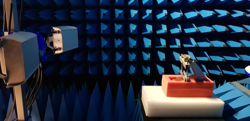
Introduction                                                                            3

1.2    Scope and Contributions of the Thesis

The goal of this thesis is to better characterize the PIM phenomenon in multiband
radio systems. This characterization covers the basics of IMD, the underlying physics
behind the nonlinear behavior of passive components that are prone to generate PIM
when several Tx carriers flow through them, the exacerbation of the problem due to
the enhancements of radio systems and corresponding mitigation techniques and, lastly,
an analysis on external PIM given the measurements performed. While it is difficult
to cover all the details associated with PIM in one thesis due to the complexity of the
problem, the focus of the measurements is on external PIM since this part of the problem
has been long overlooked.

The first contribution of this thesis is the extensive characterization of the PIM phe-
nomenon made throughout the second and third chapter. Starting with the basics of the
IMD to understand the concept, we then review the physics that trigger the nonlinear
behavior in both types of PIM (internal and external), which generate the spurious spec-
tral emissions. For internal sources, studies in the past decade, have concluded that one
of the main contributors for this phenomenon is electro-thermal (ET) conductivity along
with the mechanisms of electric tunneling in contact junctions. For external sources, the
main contributor remains to be the phenomenon called the “Rusty Bolt” effect, however,
PIM can still be generated of scattering in simple metallic sheets. Both of these are ex-
plained by the same approach. Next, we review the enhancements of the radio system,
highlighting key features that have exacerbated the PIM problem, particularly CA and
increased complexity of BS. By using broader, modulated carriers instead of narrowband
ones, the spectral regrowth is increased, worsening the interference issue. To finish this
characterization, we review current PIM mitigation techniques used by manufacturers
and operators. The strategy of physical techniques is to avoid the trigger of nonlinear
behavior on passive sources whereas the strategy of the radio integrated techniques is to
avoid PIM interference by relying on the mathematical model, e.g., frequency planning,
lower Tx power, etc.

The second contribution of this thesis is the analysis of the measurements in the fourth
chapter. The measurement setup emulates different real scenarios of external PIM.
Inside an anechoic chamber a BS transmits a multicarrier signal towards several metallic
objects placed within the RF path. By analyzing the power spectral density (PSD) of the
PIM observed in each antenna element, we derived key observations regarding external
PIM, especially the correlation of observed PIM power with the BS transmitter and
PIM source. From these, it is possible to improve the understanding of external PIM,
namely the physics involved in this scenario. Lastly, we review a digital PIM cancellation
algorithm by applying one to the measurements.
Introduction                                                                             4

1.3     Thesis Outline

Chapter 2 of this thesis gives a literature review of intermodulation distortion, internal
and external PIM sources in radio systems, the physics of the nonlinear triggers behind
PIM, and an understanding on how PIM is generated.

Chapter 3 of this thesis addresses the evolution of radio systems since the time where PIM
first had its effect. In addition, it also accounts with the exacerbation of PIM generation
in these modern radio systems due to the assiduous enhancements for increased data
rates, especially the enlargement of bandwidth by CA and possible PIM sources in the
transmission by the increase in BS complexity. Lastly, this discussion is complemented
with an overview of existing PIM mitigation techniques used by manufacturers and
operators, both physical and radio integrated.

Chapter 4 of this thesis investigates the relation between observed PIM power in the
Rx, possible external PIM sources, and Tx. This is done by assessing PIM power on
the antenna elements, namely by analyzing PIM’s PSD on antenna’s polarization. This
analysis is based on the contents reviewed in the previous chapters. Lastly, a PIM
cancellation algorithm (radio integrated mitigation technique) is implemented in the
results to assess its performance.

Chapter 5 contains a summary of the work performed, the results obtained, and the
significant outcomes from this thesis work.
Chapter 2

Fundamentals of Passive
Intermodulation

In any RF communication system, an ideal behavior is strived for, which translates into
components with linear relation. Unfortunately, it is unavoidable due to the presence
of weak intrinsic nonlinearities. Such nonlinearities result in interference problems, or
intermodulation and harmonic distortion. Intermodulation occurs when an input signal
composed of a sum of frequencies passes through a nonlinear system, generating new
frequency content. The mixing of the fundamental frequencies creates new frequency
components that are integer multiples of the frequencies of the input signal [1, 2, 3]. IM
content appears both above and below the fundamental frequencies in the spectrum, and
occurs in both active and passive “circuits”. An active circuit is driven by a (voltage)
source whereas passive circuit does not require power. For instance, an active circuit
can be the output stage of an amplifier, mixers, etc. A passive circuit on the other hand
could be an RF connector, antenna element, a metal sheet, etc [2, 4, 5, 6]. In this thesis,
the focus is on IMD caused by passive sources, and its implications on radio system per-
formance. However, we first briefly review the fundamental of passive intermodulation
distortion in this chapter. Thus, in the following section, the mathematical formulation
of the IMD is presented, which is followed by a review of the physics behind the most
common PIM sources, e.g., triggering mechanisms.

2.1     Intermodulation Distortion

Intermodulation becomes an interference problem when, in the RF spectrum, the IM
frequencies generated by the circuits fall into the receiver bands near the transmitter
signals. To develop a mathematical model of IMD, consider a simplified case where our

                                            5
Fundamentals of Passive Intermodulation 6
input signal denoted here as Vi , is composed of two tones with frequencies f1 and f2 ,
with corresponding amplitudes of A1 and A2 , which can be written as
Vi (s) = A1 cos(2πf1 t) + A2 cos(2πf2 t). (2.1)
This signal then passes through a non-ideal and, therefore, nonlinear current-voltage
(I-V) system, whose transfer function is represented by a nth-order power series with
coefficients K1 , K2 , K3 , ... The output signal of the nonlinear system, denoted as Vo , can
be described as
Vo (s) = K1 Vi + K2 Vi2 + K3 Vi3 + .... (2.2)
Note that, in the series (2.2), the larger the K − th coefficient, the more dominant is the
nonlinear term, i.e., the bigger the nonlinear contribution. Upon combining both equa-
tions and expanding the series terms using the trigonometry identity and the Binomial
theorem, additional terms at new frequencies are generated [4, 5, 7]. These spurious fre-
quency components are either harmonics (multiples) of the original signal or the result
of the sum or difference of the original signals frequencies. These additions and subtrac-
tions of the original frequencies f1 and f2 are named IM products, or frequencies, that
follow the relationship,
fIM = nf1 ± mf2 , (2.3)
where n and m are integer coefficients. The sum of the absolute value of these coefficients
provides the order of the IM product. For instance, 2f1 ± f2 are 3rd order IM products
(|2| + |±1| = 3), 3f1 ± 2f2 are 5th order IM products and so on. Despite some of the
higher and lower products being easily filtered out, odd order IM frequencies are of
most concern since they are typically located close to the original signals (if the original
frequencies in the original signal are close, which is common for multicarrier signals). An
example of an output spectrum showing the full extent of this phenomenon in frequency
is displayed in Figure 2.1. In general, the proposed concept can be extended to multiple
frequency components, for example, in the case of three frequency components mixing
in a nonlinear system, the corresponding third-order IM products (IM3) would be f1 ±
f2 ± f3 .
In case the signals are modulated, the bandwidth (Bw) of the IM products created must
be considered, not just the center frequency. The bandwidth of the IM products is wider
than the original signals bandwidth, and scales with the order of IM. For instance, if bothFundamentals of Passive Intermodulation 7
f1 f2
f 1+f 2
f 2-f 1
2f1-f 2
2f2-f 1
2f1
2f2
f1
3f1-2f2
3f2-2f1
2f2-2f1
Non-linear
3f1-f 2
3f2-f 1
Function
4f1-3f2
4f2-3f1
f2
DC Tx1 Tx2 f
Fig. 2.1: Intermodulation frequency spectrum
input signals are 1 MHz wide, the third-order product will have a 3 MHz bandwidth,
the fifth-order product will have a 5 MHz bandwidth, and so on [6]. So, it is possible
to conclude that, if both original signals have the same bandwidth then the IM product
bandwidth is the original signal bandwidth multiplied with the IM product order number
[3]. Likewise, for different bandwidth modulated signals, the IM products bandwidth
derives from equation (2.4) [4]
BwIM = |n|Bw1 + |m|Bw2 . (2.4)
Another important consideration of the IM products is the respective amplitudes. IM
products have small amplitudes if the input power on the signals is low, however, if the
input power is high (which is the case in radio systems) the amplitudes will also increase.
From mathematical expressions developed in [4, 5, 7], if we increase the input signals
such that the desired output power is increased by 1 dB, the IM3 product amplitude
increases by 3 dB. In theory, the relation between fundamental signal power and the IMD
distortion components power is directly proportional, with the slope being the product
order number. However, in practice, the power level of the measured IM products are
lower than the theory as proved in [7, 8, 9]. Figure 2.2 shows the theoretical and realistic
plots for output IM3 product signal. It also shows intersection of the theoretical line
extension of output IM3 signal and the desired output power ratio, or the third order
intercept (TOI) point. This is the point where the power growth of the intermodulation
product intersects, or is equal to, the output power growth of the fundamental signal
[10, 11, 12]. In general, the output power of the intermodulation intersect point (OIP)
can be calculated according to the equation:
OIPN = Pout + |IMN /(N − 1)| , (2.5)Fundamentals of Passive Intermodulation 8
IP2
IP3
Pout (dB)
1:1 3:1 2:1
Pin (dB)
Fig. 2.2: Representation of intersection points (IP) of the 2nd and 3rd order IM prod-
ucts with the desired output power, red, green, and blue respectively. The dashed lines
represent the theoretical slope from the calculation whereas the full line represent the
actual plot.
where Pout is the output power of the fundamental signal, N is the order of the product,
and IMN is the level (in dBc) of the intermodulation product relative to the fundamental.
By solving the previous equation in order to IMN and obtaining the distortion values,
it is possible to determine the amplitudes for each IM product. Higher-order terms have
lines with a sharper slope meaning their amplitude variation will be higher, however,
they are restrained due to a lower OIP and spread over a larger bandwidth. Thus, in
addition with the mathematical expansion previously mentioned, we denote that the
amplitude of each order IM is lower than the order before, i.e., 5th order IM products
have lower amplitude than 3rd order IM products, 7th order IM products have lower
amplitude than 5th , and so on. Nevertheless, the increase in input power leads to higher
IM products which may block desired Rx signals.
In conclusion, IMD is a phenomenon characterized by the transmitted signals that are
mixed in the nonlinear device, e.g., respective carrier frequencies, bandwidth and power.
This new frequency content, or IM products, are characterized by the same parameters.
However, the impact of the distortion is also dependent on the Rx characteristics like
sensitivity level of the radio systems.
2.2 Sources of Intermodulation Distortion
As mentioned in the beginning of the Chapter, IMD is the result of two or more sig-
nals interacting in a nonlinear device to produce unwanted signals. This mainly occursFundamentals of Passive Intermodulation 9 in active circuits (devices) such as amplifiers and mixers. In a radio system, nonlin- earity of the power amplifier (PA) has the most significant impact on the transmitter output spectrum. The relative strength of these spurious IMD products can be very strong. In active components such as the PA, intermodulation can be more predictable. This is mainly due to existing models based on measurements taken from specific PA [13, 14, 15]. The nonlinearities from the PA derive from a phenomenon called gain compression. It occurs when increasing the input power in the amplifier does not result in the corresponding increase in the output power when operating near the maximum power. Generally, nonlinearity from active devices can be predicted, and there is already some extensive research on how to model these type of nonlinearities. [3, 4, 16] To a lesser extent, IMD can occur in passive circuits, e.g., passive devices or compo- nents. PIM distortion classifies the effects of the unwanted IM products generated by the nonlinear properties of a passive component in a radio communication system. As stated before, these products may lead to interference in the receiver bands of several RF systems since they can likely obstruct a channel, also leading to a reduction in channel’s signal to noise ratio [1, 3, 4]. In general, the occurrence of the nonlinearities associated with the passive components are hard to predict, and the strength of the products de- pends on the strength of the nonlinear relation. However, there is extensive research on the mechanisms that generate the nonlinear behavior. Thus, it is possible to distinguish different types of PIM sources based on the nonlinear triggering mechanisms. In the following section, we classify the different types of existing PIM sources that are capable of producing IM products, or PIMP. 2.2.1 Classification of PIM Sources PIM has been known as a potential interference source in radio communications systems for a long time, with first studies dating back to 1989-90 [5, 17]. However, due to the adoption of wideband multicarriers signals and increasing saturation of the frequency spectrum, PIM problem has started to regain considerable interest in recent years. In general, PIM distortion can be classified into three distinct types: design PIM, assembly PIM and rusty bolt PIM, [18]. This characterization is based on different types of nonlinear trigger mechanisms that generate PIM interference which, in turn, can require a different solution. Design PIM refers to the choices taken by designers when choosing the layout members, in other words, picking components based on trade-offs of size, power, rejection and PIM performance. Assembly PIM designates the interference created by the degradation of the installed system over time, based on the quality (materials, robustness, stability, interface) of the components and surrounding environment. Rusty bolt PIM is associated
Fundamentals of Passive Intermodulation                                                   10

with reflections of the downlink frequencies towards the uplink in metallic objects (rusty
fence, barn, etc.) in the beam’s propagation path. Essentially, any interference signals
that can couple into the radio receiver and has significant power than the desired received
signal can lead to receiver desensitization. [18]

Based on the short description of PIM above, it is beneficial to, from now on, classify
PIM sources into two types, internal and external. Internal PIM couples design and
assembly PIM sources like coaxial cables, connectors, waveguides, antennas, filters, etc.
[5, 6, 17, 19, 20]. External PIM refers to sources beyond the antenna such as support
structures, tower and masts, wire fences and nearby metallic objects that re-radiate the
prejudicial spurious emission towards the Rx. [5, 6, 18]

The signals mixing in a nonlinear passive source normally come from transmitters shar-
ing an antenna structure or nearby towers with conflicting antenna patterns. Some of
the triggers that derive the nonlinear I-V relation in the passive components to generate
the mixing of the frequency are damaged or poorly torqued RF connections, contami-
nation (oxide, dirt, etc.), fatigue breaks, cold solder joints, electro-thermal conductivity,
metallic material and corrosion. These mechanisms are all inherent to components of
the radio system BS, e.g., internal sources. Each component has its own method to
generate PIM. These methods described here are unavoidable, especially PIM due to
ferromagnetic and ferrimagnetic materials since they are widely used in infrastructures
and microwave components like isolators, circulators, resonators, etc. [1, 6, 7, 21, 22]

In addition to these potential sources, nearby metallic objects are prone to generate
PIM as well. Commonly seen in rusty metallic objects, PIM generation in external
sources is commonly associated to the “Rusty Bolt” effect. However, it can still occur
by scattering of the surface of external metallic objects. These sources are located beyond
the antenna, typically in a site. For instance, sheet metal roof vents, loose cable hangers
behind the antenna, overlapping layers of metal flashing are some of the possible existing
objects that can radiate IM products back into the antenna. Also, depending on the
site configuration, there can be multiple external PIM sources radiating simultaneously,
both in front of and behind the antenna. [23, 24, 25]

On the upcoming sections, the physics of the generating mechanisms for the two possible
type of sources, internal and external, are described in Section 2.3 and Section 2.4,
respectively.
Fundamentals of Passive Intermodulation                                                 11

2.3     Internal PIM sources

In this section we discuss the physics of the triggers of the nonlinear behavior account-
able for PIM generation in internal sources. Since most of these processes can arise
from the same source, it is difficult to establish which one is the dominant during the
PIM generation process. This is mainly due to the variety of models that exist to
describe the different triggers, and the impossibility to concretely assess in a real ap-
plication. Currently, it is known that several physical mechanisms are responsible for
generating PIMP, namely, electron tunneling and thin dielectric layers between metallic
contacts, micro discharge between microcrakcs and across voids (multipactor discharge),
nonlinearities associated with dirt and metal particles on metal surfaces, high current
densities, nonlinear resistivity of materials used, nonlinear hysteresis (memory effects)
due to ferromagnetic and ferrimagnetic materials, electro-thermal (ET) conductivity ef-
fects and poor workmanship that causes loose connections, cracks and oxidization at
joints, [1, 5, 17, 21, 26].

Until recent studies, [1, 27, 28, 29, 30, 31], contact mechanisms in RF components were
considered the main source of internal PIM in radio system elements such as filter,
antennas, connectors etc. However, ET research surfaced and classified itself as another
important contributor for PIM generation in internal sources. To a lesser extent, dirt
particles and corrosion (contamination) still remain as a severe source of PIM and it
is a compulsory problem to deal with in radio systems. Since the physics of contact
mechanisms explain why corrosion can also generate PIM, the explanation of the triggers
will focus on contact mechanisms and ET. This explanation will also play an integral
role when assessing the results derived from the measurements in Chapter 4.

2.3.1    Contact Nonlinearities

As stated previously, one of the main mechanisms responsible for PIMP generation are
the nonlinearities involved in metal contacts. Two physical contact situations can oc-
cur, the metal-insulator-metal (MIM) situation and the metal-metal (MM) situation.
Each of these physical structures, MIM and MM contacts, have several of their own
distinct nonlinear mechanisms. MIM structures are more susceptible to electron tunnel-
ing ,thermionic emission and corona discharge. MM structures, on the other hand, can
create diode like junctions due to differences in metal work functions as well as nonlinear
contact resistances due to thermal processes such as expansion and thermal variation
[1, 21]. These two contact types may occur by a multitude of ways, especially since they
are dependent on both ends of the contacts topography and pressure.
Fundamentals of Passive Intermodulation                                                  12

In general, it is impossible to achieve a full smooth surface on the termination of radio
components during their fabrication process. When coupling two radio components, at a
microscopic level, both contact surface topographies possess numerous peaks in random
positions and a native oxide or sulfide layer covering it. The thickness of this layer
depends on the chosen metals, and is usually in the order of couple nanometers [32].
Therefore, contacting two surfaces of this nature is comparable to contacting needle of
various lengths [1, 21]. From this observations, one can assume that the “real” contact
area is merely a fraction of macroscopic contact and, it is only happening in peaks making
contact. Likewise, due to surface imperfections, the MM situations only occur at the
microasperities where the mechanical pressure was strong enough to force the junction
of the peaks. The analogous MIM situation occurs in case that the mechanical pressure
is insufficient to pierce through the thin dielectric layer covering the metal’s surface
[1, 21, 32]. Hence, due to surfaces topology, a contact can be seen as a combination of
both types of structure. However, an increase in pressure translates into an increase in
mechanical deformation, which enhances the size of the “real” area as it is forcing more
microasperities connections, so it can determine whether MM occurs more often. Based
on the factors that define the type of structure, e.g., deterioration, metals used and
cleanliness, different models exist to describe the nonlinearities that appear [21, 32, 33].

Figure 2.3 shows the physical situation described above, where the current is constricted
to flow through the microasperities. The determination of whether it is MM or a MIM
scenario depends on whether there is a thin dielectric layer in between the microasper-
ities, or appearance of corrosion in the void region. Nonetheless, the number of MM
and MIM scenario depends on the amount of pressure applied. The PIM distortion
generated at a junction can comprise of several contributions, either from MIM or MM,
however some contributions are higher [1, 21, 32, 34]. In most radio systems, the applied
pressure connecting two radio components can decrease, it is very likely that the main
source for IMD occurs from MIM regions, especially since a high number of contacting
zones can appear. In the following subsection, MIM situation is further explained.

2.3.1.1   Metal-Insulator-Metal situations in a RF system

The physic phenomenon responsible for the nonlinear behavior presented in MIM sit-
uations is called tunneling theory as mentioned before. The general idea is that the
current, or electrons, flow through a forbidden region between two propagating medi-
ums. In MIM type of structures, the dielectric layer refers to this forbidden region and
introduces a potential barrier that the electrons can not overcome unless the amplitude
of the wave function (or current as called here) can exponentially decay to the other side
of the barrier due to the transmission coefficient. The tunnel current between metals can
Fundamentals of Passive Intermodulation                                                  13

                                                    Metal

                   Air Regions                  Air Regions             Air Regions

                                                Metal

         Fig. 2.3: Constriction of current in the connection between microasperities

be obtained using the Simmon’s model, where the nonlinear I-V relations are portrayed.
Given this nonlinear relation, IM products are generated. [1, 21, 32, 35]v

Besides electron tunneling, thermionic emission and corona discharge are another phe-
nomenons that occur in MIM. In thermionic emissions, electrons jump the aforemen-
tioned potential wall due to thermal energy. By doing so, a nonlinear current is generated
that is dependent on barrier thickness. This current accumulates with the tunneling cur-
rent but is typically weaker, therefore negligible. Although its current contribution is
considerably less than the tunneling current, it is relevant to point that these weak non-
linear currents can be accumulated at the interfaces. Corona discharge is a process that
usually occurs in low pressure cases, i.e., when the junction start to loosen up. In this
process the current flows from a high potential conductor (radio component) towards
a neutral fluid, in our case, air [1, 32, 35]. In summary, one can deduce that the con-
tribution for PIM distortion in contact situations can simultaneously be from multiple
mechanisms.

In [34] and [36], the authors corroborated the relationship between contact mechanisms
and nonlinear I-V equations. After deriving pressure-dependent nonlinear I-V equations
for metallic contact interfaces and PIM models, the consequential PIM’s level can be
obtained. It is dependent on contact resistance, surface current density and the nonlinear
current coefficients. In other words, MIM contact structures can be seen as transmitters
(Tx) of PIM signals, whose total power (in dBm) can be represented as


                                                Pint [J(V )]
                            PPIM = 10 log                          (dBm),              (2.6)
                                                 1 × 10⁻³
Fundamentals of Passive Intermodulation 14 where Pint [J(V )] is the total sum of the current generated by the several nonlinearities (transmitters) mechanisms of the contact. The mathematical approach of obtaining these currents is described in detail in [32]. There are several key conclusions that can be drawn from the discussion above. First of, as the mechanical load increases, the PIM level decreases much faster since the area of contact is dramatically increased. Hence, the thicker the dielectric layer in between contacts, the higher the PIM level. Secondly, for proper mechanical connections, i.e., no loose contacts, the cleanliness of the surface determines the PIM level. Based on these arguments, one can argue that the use of soft metals for contacts as the inherent coating and oxidation is thinner. Unfortunately, for this type of materials, there is the possibility that the deformation from the thermal increase of applying mechanical load permanently changes the surface’s original shape. This leads to a decrease in contact pressure when the contact temperature unavoidably decreases, which creates a gap between surfaces. As a consequence, inside the gap, dirt particles can intrude, creating undesired MIM PIM transmitters. Thus, the emphasis on cleaning and maintaining the radio system structure is enhanced. In sum, PIM interference can be originated in contacts, mainly due to the ferromagnetic materials and dirtiness. These mechanisms are present throughout the RF network, beyond contacts and junctions, including transmission lines, resonant structures and antennas. Nonetheless, physical situation embedded in the radio system components generate PIM signals that can be accumulated throughout the system. These interfer- ences become more and more pronounced in high power BS radio systems, where the downlink signals contributing to PIM generation are substantially strong. 2.3.2 Electro-Thermal PIM Sources In the previous subsection, we review how contact mechanism in BSs components can induce PIM interference. Additionally, these high power transmit signal can also produce electro-thermal effects which also induce PIM. The constant change in both thermal and electrical domain when modulated RF signals travel lead to time variant nonlinear conductivity, which is responsible for PIMP generation [1, 30]. As stated previously as well, PIM generation due to ET conductivity are also one of the main contributors to aggravate the problem in internal sources, so its physics are discussed in the following subsections.
Fundamentals of Passive Intermodulation                                                  15

2.3.2.1   Electro-Thermal Theory

In general, metals possess disturbing influences that impede the free flows of the electrons
under a electric field, known as electrical resistance. According to the Wiedemann-Franz
Law, metals also exhibit a thermally-based resistance, Rth [37]. Therefore the specific
resistivity of a material can be written according to a function of temperature (T ),
expressed as equation (2.7) [1, 27, 30]

                              ρe (T ) = ρe0 (1 + αT + βT 2 + ...),                     (2.7)

where ρe0 is the static resistivity constant and α and β are temperature coefficients of
resistance (TCR).

In a resistive element, the heat generated per unit volume, Q, is directly proportional to
the current density, J. Thus, the electrical domain is coupled with the thermal domain
according to equation (2.8)

                                           Q = J 2 ρe .                                (2.8)

The time needed to conduct the heat from the element to its surrounding environment
at a given rate is captured by the thermal capacity Cv , and it is propelled by the heat
conduction equation, given by equation (2.9) [1, 27, 30].

                                         OT         ∂T
                                   O·(       ) − Cv    = Q.                            (2.9)
                                         Rth        ∂t

Combining equations Equations (2.7) to (2.9), equation (2.10) is originated, which de-
scribes a nonlinear system. This is a crucial result because it means that the electro-
thermal process can be separated into static and dynamic components, with static and
dynamic power signals Ps and Pd , respectively. They are dissipated through the respec-
tive static and dynamic resistance components Rs and Rd , respectively. The total power
dissipated over these resistive components is converted to the heat signal Q(Ps + Pd )
and filtered by the material’s thermal response (baseband lowpass). This is relevant
because, in a situation where two or more signals are applied to a resistive element
(two-tone case), the instantaneous power of the signal varies periodically at the beat
frequency of the two-tone input to the device. If the beat frequency is within the ther-
mal bandwidth of the lowpass filter, periodic heating and cooling of the element occurs
at baseband frequencies due to the oscillation of the instantaneous power. Consequently,
Fundamentals of Passive Intermodulation 16
the resistance of the element varies periodically. This periodic oscillation creates a pas-
sive mixer producing intermodulation distortion through up conversion (heterodyning)
of the envelope frequencies at baseband to RF frequencies [1, 27, 30].
OT ∂T
O·( ) − Cv = J 2 ρe0 (1 + αT + βT 2 + ...) (2.10)
Rth ∂t
The process described above is displayed in Figure 2.4. In sum, the electrical and ther-
mal domain couple at RF frequencies due to low frequency variations in the dissipated
electrical power. Note that the filtering property response (lowpass) of the thermal
domain is due to the diffusive nature of heat conduction [1, 30, 31].
Thermal Response
PI (f,T)
f1 f2 f
(a)
IM products
VO (f,T)
f1 f2 f
(b)
Fig. 2.4: Passive mixing inherent in electrical and thermal coupling process: (a) input
power spectrum Pi , resulting from two-tone excitation, interacting with the thermal
response of the passive component, and (b) corresponding output spectrum voltages Vo
after electro-thermal mixing has occurred
2.3.2.2 Distributed PIM sources
Passive nonlinearities in modern radio systems can be categorized in two main cate-
gories, lumped, where PIM in generated by one main source, typically metal-to-metal
contacts, and distributed, where the sources are scattered throughout the whole infras-
tructure. Similar to the MIM scenario, in modern base stations, weak passive nonlinear-
ities due to ET effects that act like PIM sources are spread throughout the system. The
temperature’s dependence on conductivity produces appreciable electrical distortion in
microwave elements as concluded in [1, 30]. So, due to electro-thermal effects previously
explained in 2.3.2.1, distributed PIM distortion is typically modeled as a nonlinear trans-
mission line (NTL). Note that this model can be used to describe PIM generation due
to ET conductivity in passive components like coaxial cables and microstrips. TheseFundamentals of Passive Intermodulation 17
Δt Δt z
Δz Δz
E1
-E3 +E3 -E3 +E3 -E3 +E3
V(t,x)
z
Fig. 2.5: PIM’s signal strength sequential increase due to the generated fields in non
linear consecutive points in the transmission line
elements, alongside contact terminations (lumped components), play a major role on
generating PIM in a radio system.
In the NTL model, the PIM distortion is generated by singular elements of a nonlinear
transmission line. The sum of all the effect reproduced by the cells generate the total
nth order PIM outage power due to ET effects. For a detailed explanation of how PIM is
generated in each infinitesimal element, the reader is referred to [1, 29, 30]. However, to
briefly summarize it, in a line component, a nonlinear electric field (E) of IM products
is generated through the nonlinear current (J) produced by the varying heat dissipation
(Q). The PIM signal is the sum of the electric fields accumulated throughout the line
via different components. Basically, each line element functions as a nonlinear generator
whose signal power depends on the element’s impedance (varies throughout the line). It
is relevant to note that two electric fields are generated at each point, the forward one
and the reverse. Yet, due to destructive interference after line’s length ∆z = λ/4, the
latter one is negligible. However, PIM can still travel in the reverse way by reflecting
the forward PIM signal at the line’s termination. In Figure 2.5, a representation of
PIM generation from NTL model is displayed. In summary, one can deduce that the
contribution for PIM distortion due to ET conductivity can be from the multiple resistive
elements in which the current flows through.
With this, all main internal PIM sources in radio system components are accounted for.
In the following section, we discuss the physics of external PIM sources to finalize the
theoretical characterization of the phenomenon.
2.4 External PIM Sources
So far, the discussion has been focused on nonlinear triggers of internal PIM sources,
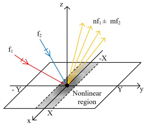
however, the PIM problem goes beyond the internal constituents of a radio system.Fundamentals of Passive Intermodulation 18 PIM can also derive from unpredictable and uncontrollable external sources. In either case scenario, indoor or outdoor, solving the problems of site interference unveils the issues associated with external sources of PIM. In [23], the author performed a study regarding the challenges in a site. It concluded that potential non-linear objects such as sheet metal vents, metal flashing, ceiling tile frames, street lamps, etc. that are typically present in the RF path might generate IM products and re-radiate them into the system. As mentioned previously in 2.2, this effect is commonly referred to as the “Rusty Bolt” effect, demonstrated in [25]. Consequently, antenna location and orientation to remove external sources from the system’s RF path is extremely important. Antenna polarization also as an effect on how energy couples into the nonlinear object and how it is received back into the Rx. As shown also in [23], different antenna’s linear polarization (+45◦ and −45◦ respectively) lead to distinct levels of third order IM products generated externally by overlaying metal sheets. In a typical FDD radio system, Tx and Rx functions are coupled into one antenna and, in a co-site scenario where multiple radios from the same or different operators are deployed, several antennas and bands act simultaneously. Distortion of the signals by intermodulation is a severe concern in site integration. PIM interference in the antennas is usually attributed to internal sources such as contact nonlinearities, explained and cited in 2.3.1 and 2.3.1.1, material nonlinearities, and electro-thermal nonlinearities [1, 5, 17, 20, 38, 39, 40]. However, as it was previously mentioned in section 2.2, PIM can be generated externally (beyond the base stations), in simple metallic components. Simple objects in the RF path like a rusty junctions or metal structures can either generate or reflect PIM products that are captured by the antenna as noise [5, 41, 42, 43]. The characterization of physics behind the triggering mechanisms of external PIM sources is explained in the following subsections. 2.4.1 Reflection on Metal Surfaces As stated previously, metal flashing in the RF path can generate PIM. Not only this specific case, but for any finite metallic or dielectric component in the beam’s path. Although likely, a transient situation will not be considered for simplicity reasons. Con- sider the simple situation where a radio is transmitting towards a metal sheet, showcased in Figure 2.6. The incident wave reflects of nonlinear metallic surface. Consequentially, the scattered electric field by the surface can be calculated by the physical optics (PO) approach since it is a well-known and efficient method for high frequency diffraction techniques [44]. The PO approach abides that a local surface current is induced by the incident wave on the illuminated part of the body’s surface element. Consequently, an- other scattered field is created by summing the contributions of each lit element of the
You can also read