CHECKWEIGHER USING AN EMFC WEIGHING CELL WITH MAGNETIC SPRINGS AND AIR-BEARINGS
←
→
Page content transcription
If your browser does not render page correctly, please read the page content below

Metrol. Meas. Syst., Vol. 28 (2021) No. 3, pp. 465–478
                                           DOI: 10.24425/mms.2021.137135

                             METROLOGY AND MEASUREMENT SYSTEMS
                                             Index 330930, ISSN 0860-8229
                                               www.metrology.wat.edu.pl

CHECKWEIGHER USING AN EMFC WEIGHING CELL WITH MAGNETIC
SPRINGS AND AIR-BEARINGS

Hyun-Ho Lee, Kyung-Taek Yoon, Young-Man Choi

Ajou University, Department of Mechanical Engineering, 206, World cup-ro, Yeongtong-gu, Suwon-si, Gyeonggi-do,
Republic of Korea, Suwon, Republic of Korea (lho3692@ajou.ac.kr, majesty17@ajou.ac.kr, B ymanchoi@ajou.ac.kr,
+82 2108 7854)

Abstract
A dynamic weighing system or a checkweigher is an automated inspection system that measures the
weight of objects while transferring them between processes. In our previous study, we developed a new
electromagnetic force compensation (EMFC) weighing cell using magnetic springs and air bearings. This
weighing cell is free from flexure hinges which are vulnerable to shock and fatigue and also eliminates
the resonance characteristics and implements a very low stiffness of only a few N/m due to the nature of
the Halbach array magnetic spring. In this study, we implemented a checkweigher with the weighing cell
including a loading and unloading conveyor to evaluate its dynamic weighing performances. The magnetic
springs are optimized and re-designed to compensate for the weight of a weighing conveyor on the weighing
cell. The checkweigher has a weighing repeatability of 23 mg (1σ) in static situation. Since there is no low-
frequency resonance in our checkweigher that influences the dynamic weighing signal, we could measure
the weight by using only a notch filter at high conveyor speeds. To determine the effective measurement
time, a dynamic weighing process model is used. Finally, the proposed checkweigher meets Class XIII of
OIML R51-1 of verification scale e 0.5 g at a conveyor speed of up to 2.7 m/s.
Keywords: checkweigher, magnetic spring, electromagnetic force compensation.
                                                                                © 2021 Polish Academy of Sciences. All rights reserved

1. Introduction

    A dynamic weighing system, also called a checkweigher, is a device that measures the
weight of products that are continuously fed through a conveyor and inspects them for defects by
comparing their weights to the nominal mass of the product. In general, a conveyor is installed on
the weighing cell for continuous measurement, and a loading and unloading conveyor is installed
in front and at the back of the weighing cell [1]. As the automation process of the manufacturing
and packaging industry has developed rapidly in recent years, there is a rising demand for
an increase in the conveyor speed of the checkweigher and the level of individual weighing
accuracy [2]. Most modern checkweighers can measure with a throughput of up to 600 items/min

Copyright © 2021. The Author(s). This is an open-access article distributed under the terms of the Creative Commons Attribution-
NonCommercial-NoDerivatives License (CC BY-NC-ND 4.0 https://creativecommons.org/licenses/by-nc-nd/4.0/), which permits use, dis-
tribution, and reproduction in any medium, provided that the article is properly cited, the use is non-commercial, and no modifications or
adaptations are made.
Article history: received March 15, 2021; revised April 29, 2021; accepted June 1, 2021; available online June 13, 2021.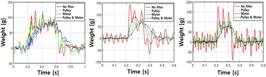
H.-H. Lee et al.: CHECKWEIGHER USING AN EMFC WEIGHING CELL WITH MAGNETIC SPRINGS AND AIR-BEARINGS

and with a high repeatability of 0.01 g in various packaging processes ranging from a few grams
to several hundred kilograms [3]. In checkweighers, measurement accuracy is greatly influenced
by disturbances such as resonant vibration of the mechanical structure, vibrations from conveyor
motors and pulleys, and environmental vibration. To compensate for those disturbances, dynamic
models for checkweigher [4–7], digital notch filters [8, 9], time-varying filters [10, 11], adaptive
filter [12] have been studied. Futhermore, supplementary accelerometer measurements [13],
freqeuency analysis using a least-mean-square algorithm [14], and system identification [15]
have been tried to estimate the disturbance freqeuncy accurately.
     A strain gauge load cell or an electromagnetic force compensation (EMFC) weighing cell are
commonly used as weighing sensors in checkweighers [10]. In the case of the strain gauge load cell,
a compliant structure of the load cell is deformed by the weight of the object, and the deformation
is measured by the strain gauge on the structure. This method exhibits relatively high ruggedness
owing to increased stiffness of the structure of the load cell and has the advantage of low cost, so
it has been mostly applied to heavy weight applications of 100 g or more. Thus, owing to its limit
of measurement resolution, the strain gauge load cell is not appropriate for high precision mass
measurement such as required in the pharmaceutical process which requires resolution of 1 g or
less [8,12]. EMFC weighing cells consist of a compliant hinge-based Roberval mechanism, a lever
mechanism, an electromagnetic actuator, a displacement sensor, and a feedback controller. When
an object is loaded onto the weighing platform hanging on one end of a lever, the other end of the
lever elevates, and the change in the position of the lever ends is measured using the displacement
sensor. The electromagnetic actuator balances the lever using the feedback control, and the current
of the actuator corresponds to the weight of the object. The more compliant the lever, the higher
the measurement sensitivity of the weighing cell. The static weight measurement of these EMFC
weighing cells has a high resolution of up to 0.02 mg and a repeatability of 0.1 mg [16, 17].
Therefore, EMFC weighing cell is more favorable in the high precision inspection process with
dynamic weighing.
     To achieve high throughput and weighing accuaracy simultaneusly in dynamic weighing,
precise system modeling and optimization of the controller are required because the weighing cell
calculates a weight by feedback control [4–6]. Conventional EMFC weighing cells have a natural
frequency of less than 10 Hz due to their low stiffness of the compliant hinge mechanism. This low
natural frequency not only limits system bandwidth, but also introduce a time delay when applying
filters to remove noise generated by the system resonance. In the structural viewpoint, unlike the
strain gauge checkweigher with relatively high rigidity as is inherent in strain gauges, the EMFC
checkweigher has low rigidity which may lead to fatigue failure of the hinges during repeated
measurements. The complex structure also hinders the wider application of EMFC-weighing cells.
Previously, Yoon et al. [18] proposed a new EMFC weighing cell using the non-contact gravity
compensation characteristics of magnetic springs and frictionless air bearing guides instead of
a compliant hinge guide mechanism. In the proposed system, gravity compensation ablity of
the magnetic spring can effectivly compensate heavy system deadweight including conveyors.
Also, near-zero negative stiffness characteristic of the magnetic spring helps avoid the system
resonance while maintaining stiffness as low as that of the flexure mechanism. This feature is
enabled by the magnetic levitation principle [19]. It is also commonly used in high-precision
motion stages [20] or active magnetic bearings [21]. Moreover, high system ruggeddness of the
air bearings can protect the system from fatigue, failure or impact arising from consequtive
weighing.
     In this study, we propose a checkweigher capable of dynamic high-speed weighing of objects
under 100 g by adopting the previously studied EMFC weighing cell. The magnetic springs
in the weighing cell are designed to compensate for the moving mass, including the con-

466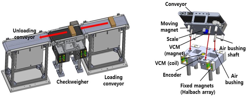
Metrol. Meas. Syst.,Vol. 28 (2021), No. 3, pp. 465–478
                                         DOI: 10.24425/mms.2021.137135

veyors, ensuring near-zero negative stiffness. We fabricated a checkweigher system including
a weighing system and the loading and unloading conveyors. The dynamic weighing process
is modeled to determine the measument timing and interval. For accurate weight measure-
ment, the major vibrational frequencies are analyzed and their effects are eliminated by digital
notch filters. In addition, in order to quantitatively evaluate the weighing performance, the dy-
namic performance was verified by referring to the R51-1 performance index provided by the
OIML [22].

2. Design of an EMFC checkweigher with magnetic springs and air bearings

2.1. Checkweigher

    Figure 1a shows a prototype of the proposed dynamic weighing system using our EMFC
weighing cell with magnetic springs and air bushing guides. It comprises a loading conveyor
for transferring an object to the checkweigher, an EMFC weighing cell with a conveyor on it,
and an unloading conveyor to deliver the object to the next process. Figure 1b demonstrates the
EMFC weighing cell, which allows relative movement of the upper part towards the lower part;
a conveyor is installed on the upper part and the lower part is fixed to the ground. Three pairs of air
bushings and their shafts are installed in both upper and lower part to form an air film between the
two, providing frictionless motion in the direction of gravity and high rigidity in other directions.
A magnetic spring consists of a cube-shaped moving magnet fixed to the upper part and a Halbach
magnet array of six rectangular parallelepiped magnets fixed to the lower part so that it surrounds
the moving magnet. Four magnetic springs compensate for the weight of the upper part and, at
the same time, provide the system a negative stiffness close to zero, enabling high measurement
sensitivity and good vibration damping characteristics [23]. A voice coil motor (VCM) is located
at the center of gravity of the system and generates a force to compensate for the weight of the
loaded object, and this weight is measured from the current required to generate this force. It
offers the advantage of being linearly responsive, and as there is no mechanical coupling between
the coil and magnet, it does not affect the system’s stiffness. In this study, in order to minimize
the vibration and stiffness change caused by the coil wiring, the system is designed as the moving
magnet type with a magnet attached to the top. The proposed weighing cell compensates for
the weight of the object by the feedback control of the upper part’s position change. Hence, the

         a)                                              b)

                  Fig. 1. Proposed EMFC checkweigher: a) total system, and b) weighing cell.

                                                                                                   467
H.-H. Lee et al.: CHECKWEIGHER USING AN EMFC WEIGHING CELL WITH MAGNETIC SPRINGS AND AIR-BEARINGS

resolution of the position sensor is closely related to that of the weight measurement. Therefore,
in the proposed system, an optical linear encoder [24] with a nanometer-level resolution was
selected as a position sensor because it is easy to install and has a good thermal stability as well
as a reasonable cost efficiency compared to an optical slit sensor in conventional EMFC weighing
cells.

2.2. Design of magnetic springs

     The main properties of the magnetic springs [18] in the proposed weighing system are the
near-zero negative stiffness and gravity compensation. Each property brings high mechanical
sensitivity and a precise weighing resolution by lowering the current applied to the actuator. For
the weighing performance that satisfies both properties, the magnetic spring was re-designed
through an optimization process, as in [18]. The optimization goal was to minimize the system
stiffness in the given constraints where the magnetic spring force was set to compensate for the
system deadweight (4.3 kg) with ±5% tolerance in the moving range of ±1 mm. The size constraint
of the magnetic spring was set to 40 mm ×30 mm ×55 mm taking into account the system volume,
and the length of the cube shaped moving magnet was fixed at 8 mm. In addition, the parasitic
forces except the measurement direction were limited to 0.5 mN to minimize parasitic motion.
The permanent magnet was modeled using a surface current model based on the Biot–Savart law,
and optimization was performed through the sequential quadratic programming method provided
by the MATLAB optimization toolbox (MathWorks Inc.). The detailed design optimization
procedure followed the method described in [18].
     Figure 2 shows the force and stiffness characteristics in the weighing (Z-axis) direction
of the optimized magnetic spring. The maximum variation in force is approximately 0.2 mN
and the RMS value of the stiffness is only 0.03 N/m, which means near-zero stiffness. Even
when the moving magnet is deviated from its original position in the x,y parasitic direction, the
change in the Z-directional force is very small, as shown in Figs. 3a and 3b. In addition, its
own X- and Y-directional parasitic forces are limited to approximately ±0.5 mN, as depicted in
Figs. 3c and 3d. Since the actual parasitic movement is limited by an air-gap clearance of the
air bearing of several micrometers or less, those parasitic forces might be much less in actual
conditions.

          a)                                                  b)

      Fig. 2. Simulation results of the: a) force and b) stiffness in the z-direction of the optimized magnetic spring.

468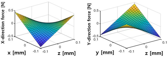
Metrol. Meas. Syst.,Vol. 28 (2021), No. 3, pp. 465–478
                                              DOI: 10.24425/mms.2021.137135

          a)                                                  b)

          c)                                                  d)

Fig. 3. Force characteristics of the optimized magnetic spring: Z-directional force over: a) the x-z plane; b) y-z plane; c)
                   X-directional force over the x-z plane, and d) Y-directional force over the y-z plane.

3. Design of EMFC checkweigher with magnetic spring and air bearings

3.1. Prototype fabrication

    The proposed checkweigher uses a voice coil motor (AVM 30-15, Akribis Systems) with
a force constant of 7.35 N/A as an electromagnetic actuator, and an air bushing (S301301, New
Way Air Bearings) with a shaft diameter of 13 mm. The fabricated magnet has a magnetic flux
density of 1.41 T and a coercive force of 1376 kA/m. Also, a linear optical encoder (Ti4000,
RENISHAW) with a resolution of 5 nm was used as a displacement sensor. Figure 4a shows the
fabricated checkweigher. The system bodies are made of aluminum alloy (AL6061). The conveyor
is equipped with a brushless DC motor (R88M-G10030H-S2, OMRON) to enable high-speed
weighing. The size of the conveyor is 300 mm in length, 180 mm in width, and 30 mm in thickness.
The measured deadweight of the uppper part including the conveyor is 4.51 kg, which differs by
0.2 kg from the predicted weight. Figure 4b presents the experimental setup of the proposed EMFC
checkweigher. Feedback control and data acquisition were performed by a real-time controller
(MicroLabBox, dSPACE GmbH). A linear current amplifier (TA105, Trust Automation Inc.) was
used to power the voice coil motor. A simple proportional–integral–derivative (PID) feedback
control algorithm was implemented using MATLAB Simulink (MathWorks Inc.) and a graphical
interface (ControlDesk, dSPACE GmbH), provided by the controller manufacturer. The loading
and unloading conveyors for transport were manufactured at the same size as the checkweigher,
and a photo sensor was placed between the loading and the weighing conveyor to record the exact
time when an object was loaded from the loading conveyor to the checkweigher.

                                                                                                                       469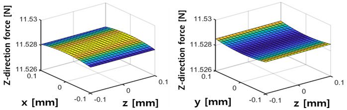
H.-H. Lee et al.: CHECKWEIGHER USING AN EMFC WEIGHING CELL WITH MAGNETIC SPRINGS AND AIR-BEARINGS

   a)                                                                    b)

        Fig. 4. Fabricated checkweigher: a) EMFC weighing cell; b) experimental setup for dynamic weighing test.

    To evaluate the stiffness of the fabricated magnetic spring, the output VCM force was measured
by varying the vertical position of the upper part from −0.5 mm to +2 mm from the original.
Since a rubber pad was installed to prevent collision, the moving range in the negative direction
was smaller than that in the positive direction. The compensation force generated by the magnetic
spring could be derived by subtracting the VCM compensation force from the system upper part
deadweight according to weighing direction. As a result, the magnetic spring stiffness could be
achieved numerically from the force difference. As shown in Fig. 5, it was confirmed that the
experimental result was within the range of the finite element model (Maxwell, Ansys Inc.) and
the analytic model, and the stiffness value measured in the experiment was negative over the
entire moving range as desired. The average stiffness value was −8.87 N/m between −0.5 mm
and +0.5 mm, which is the effective motion range of the feedback control.

                       Fig. 5. Comparison of stiffness from analytic model, FEM and experiment.

3.2. Evaluation of static weighing performance
    The fabricated EMFC checkweigher performed feedback control using a PID control algo-
rithm, as shown in Fig. 6. To minimize the effect of high-frequency noise, a low-pass filter (LPF)
with a cutoff frequency of 100 Hz was applied to the PID controller output signal and used for
weight measurement. Figure 7 shows the minimum in-position stability of both displacement
and current when the checkweigher is sufficiently stabilized in the closed-loop control in a static
situation without running the conveyors. The corresponding resolutions were calculated as a value
for 5 s: the displacement resolution was ±4.08 nm (1σ), and the static resolution was ±0.02 g

470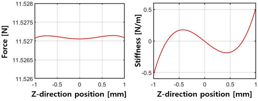
Metrol. Meas. Syst.,Vol. 28 (2021), No. 3, pp. 465–478
                                            DOI: 10.24425/mms.2021.137135

(1σ). Next, an experiment on repeatability in a static situation was conducted using a 10 g E2
grade standard with an error of ±0.06 mg. The final weight was calculated from the difference
between the average current value for 3 seconds before the weight was loaded, and the average
current value for 0.5 seconds after the current settled within ±2% of the final value. The exper-
iment was repeated ten times, and the repeatability was derived through the standard deviation
of the measured weights. The measured repeatability was 23 mg (1σ), which was similar to the
resolution value.

                        Fig. 6. Block diagram of the feedback control and weight calculation.

    a)                                                        b)

         Fig. 7. Static performances of the weighing cell: a) in-position stability and b) weighing resolution.

4. Dynamic weighing

4.1. Filtering and results
    In the case of dynamic weighing, vibration from the motor and pulley of the conveyor [6, 8],
and even floor vibrations [7] impair the measurement accuracy. A simple technique to elliminate
the effect of these vibrations is filtering weight signal with a low-pass filter or a notch filter.
Yamazaki [8] applied a finite impulse response (FIR) filter to achieve an accuracy of less than
0.7% at the conveyor speed of 2.2 m/s. Sun [9] studied an optimized digital notch filter of the
particle swarm optimization (PSO) algorithm. More advanced techinques like identification or
the adaptive method have been studied. Umemoto [12] analyzed three mechanical frequencies
that affect the measurement signal: system natural frequency, motor frequency, and belt pulley

                                                                                                                  471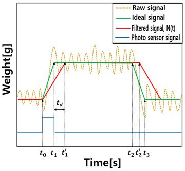
H.-H. Lee et al.: CHECKWEIGHER USING AN EMFC WEIGHING CELL WITH MAGNETIC SPRINGS AND AIR-BEARINGS

frequency, and proposed an adaptive notch filter using the least squares algorithm to achieve 0.86 g
(3σ) accuracy with a throughput of 120 items/min for 160 g weight. Pietrzak [11] used a time-
variant low pass filter to support a wide range of conveyor speeds and Sun [14] studied the self-
adaptive noise cancellation (SANC) notch filter that can find filter gains by itself. Niedźwiecki [15]
demonstrated an identification-based approach satisfying the requirements of OIML Class XIII.
In addition, there was a research on calculating the weight without using an object detecting
sensor by analyzing the dominant frequency of the weighing sensor signal [25].
     Since the weight measurement is based on the DC signal, the measurement signal can be
distorted or experience time delay when a filter is used for those low frequency disturbance
components. Therefore, an efficient filtering strategy to choose a proper filter and determine
proper weight data in accordance withthe conveyor speed is required. Our weighing cell has near
zero friction and negative stiffness due to the magnetic spring and air bushing guide, so there
was no distinct resonance at the natural frequency of the system. Therefore, it was determined
that high measurement accuracy could be achieved by using a notch filter instead of the advanced
filters described above.
     The frequency that affects the dynamic measurement for the use of a filter depends on the
conveyor speed Vcon . Based on the object’s length l, the distance between objects d, the conveyor’s
length L and throughput Tp in items/min, the conveyor speed Vcon is calculated as follows.

                                                     d = L + l,                                              (1)
                                                  Vcon = d · Tp .                                            (2)

     We evaluated our checkweigher at three different throughputs of 100 items/min, 300 items/min,
500 items/min. The motor and pulley frequencies for each throughput were calculated based on
the length of the object of 60 mm and the length of the conveyor of 275 mm. Table 1 shows the cal-
culated frequencies and the ones measured in the experiments. In the case of a conveyor speed of
0.5 m/s (100 items/min), the pulley frequency component did not appear in the measured weight
signal because it was well suppressed by the feedback controller. Among the two vibrational
frequencies, the pulley frequency has a greater influence on the weight measurement because it
is relatively closer to the closed-loop frequency. To eliminate these vibrational effects, we used
a second-order notch filter [26] for both the motor driving frequency ωm and the pulley frequency
ω p . The filter parameters were chosen through trial and error to eliminate the vibrational effect
and minimize the time delay.

                                         Table 1. Motor and pulley frequency.

                                                      0.5 m/s                1.6 m/s           2.7 m/s
                   Parameters
                                                  (100 items/min)        (300 items/min)   (500 items/min)
      Calculated pulley frequency [Hz]                   3.2                    10.3            17.2
      Measured pulley frequency [Hz]                      –                     10.8            17.9
      Calculated motor frequency [Hz]                    8.8                    26.6            44.4
      Measured motor frequency [Hz]                      8.5                    26.7            44.3

    For dynamic weighing, we tested two rectangular objects of weight 23.15 and 78.85 g which
had been fabricated with 3D printing. The details of the objects are shown in Table 2. These are
typical weight values in the pharmaceutical packaging process. The mass of the fabricated objects
was calibrated using an industrial scale of 0.01 g resolution (MW-200, CAS).

472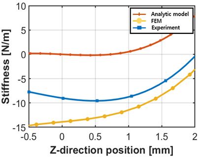
Metrol. Meas. Syst.,Vol. 28 (2021), No. 3, pp. 465–478
                                             DOI: 10.24425/mms.2021.137135

                                      Table 2. Specifications of weighed objects.

                                   Parameters                         Object A              Object B
                      Weight [g]                                        23.15                78.85
                      Width [mm]                                          80                  80
                      Thickness [mm]                                      60                  60
                      Height [mm]                                         15                  35
                      Material                                                     PLA

     In order to check the effect of each filter on the weight signal, four cases were investigated: no
filter, a filter only for the pulley frequency, a filter only for the motor freqeuncy, and both filters.
Fig. 8 shows results at three different conveyor speeds. Here, Object B was chosen because it yields
stronger vibrations due to its larger weight. At the conveyor speed of 0.5 m/s (100 items/min), the
pulley and motor frequencies are too low to apply notch filters. As shown in Fig. 8a, they distorted
the measurement signal and caused significant time delays. However, since a sufficient amount of
data can be obtained at this speed, the weight is calculated without using a filter. At the conveyor
speed of 1.6 m/s (300 items/min), the two filtered signals(green and blue respectively in Fig. 8b)
applied to the pulley frequency experienced a time delay and did not give enough effective weight
data. So, a notch filter was applied only for the motor frequency. Finally, at the conveyor speed
of 2.7 m/s (500 items/min), since the pulley frequency is relatively far from the DC component
the influence of the filter on the weight signal is not critical. When both frequencies are filtered,
the vibration is greatly reduced and the weight signal is very close to the actual weight of Object
B as shown in Fig. 8c. However, it can be seen that the unloading completion time is delayed by
tens of milliseconds compared to the raw signal.
a)                                      b)                                         c)

Fig. 8. Filtered weight signals with a) conveyor speed 0.5 m/s; b) conveyor speed 1.6 m/s, and with c) conveyor speed
                                                  2.7 m/s for Object B.

4.2. Dynamic weighing process model
    For accurate weight calculation, even in the presence of vibrations or a time delay arising
from the use of filters, the effective measurement time in which the weight signal is averaged
to calculate the final weight should be determined. Figure 9 shows a dynamic weighing process
model including raw signal, ideal signal, filtered signal and photo sensor signal. The raw signal is
the weight signal from the low-pass filter in Fig. 6, and the ideal signal is mathematically derived
taking into account only the conveyor speed. The photo sensor signal detects the entry timing of

                                                                                                                473
H.-H. Lee et al.: CHECKWEIGHER USING AN EMFC WEIGHING CELL WITH MAGNETIC SPRINGS AND AIR-BEARINGS
the loaded object: t 0 is the ideal loading start time, t 1 is the ideal loading complete time. t 2 is
the ideal unloading start time, and t 3 is the ideal unloading complete time. The filtered signal,
N (t), presents data filtered by a series of filters to reduce the influence of the motor and pulley
vibrations. The filtered signal experiences an inevitable time delay t d due to the notch filters.
Fig. 9. Dynamic weighing process model.
First, effective measurement time t e , i.e. when the object is completely loaded on the conveyor,
can be calculated through the conveyor length L, input object length l, and the speed of the
conveyor Vcon , as shown in (3).
L−l
te = = t2 − t1 . (3)
Vcon
However, in the filtered signal N (t), time delay t d must be considered for proper selection of
the effective measurement time range. The actual weight w of an object is calculated from the
difference between the average value of the weighing signal under the “loaded” condition (Wload )
and that under the “unloaded” condition Wunload . First, Wunload is calculated for a predetermined
time interval (t p ) before t 0 , and then Wload is averaged in the effective measurement time ranges
between t 10 and t 20 considering the time delay as shown in Fig. 9. When the notch filter is not
used, the effective measurement time range is between t 1 and t 2 detected by the photo sensor. The
procedure for dynamic weight measurement is described in the flow chart presented in Fig. 10.
If the delayed unloading start time t 20 exceeds the ideal unloading completion time t 3 , the next
object is loaded before the weighing of the currently measured object is completed. To prevent
this case from occurring, the effective measurement time t e is adjusted to t 3 − t 10 , which allows
maximum data to be acquired without affecting the weight measurement of the next input object.
4.3. Evaluation of dynamic weighing performance
An evaluation of dynamic weighing performance was conducted at three conveyor speeds
of 0.5 m/s (100 items/min), 1.6 m/s (300 items/min), and 2.7 m/s (500 items/min), for the two
objects in Table 2. Repeated dynamic weighing was evaluated based on the average error of the
repeated measured weights and the standard deviation of the error to verify the rating of the
proposed checkweigher through the standard performance R51-1 provided by the International
Organization of Legal Metrology (OIML) [22]. In this study, the final weight of the object was
derived based on the data repeatedly measured 10 times by the procedure in Fig. 10 for each
474Metrol. Meas. Syst.,Vol. 28 (2021), No. 3, pp. 465–478
DOI: 10.24425/mms.2021.137135
Fig. 10. Flow chart of dynamic weighing signal processing.
conveyor speed. The mean error ( x̄) and standard deviation of error (s) for each object and
conveyor speed are shown in Table 3.
Table 3. Dynamic weighing results.
0.5 m/s 1.6 m/s 2.7 m/s
Object
(100 items/min) (300 items/min) (500 items/min)
Object A x̄ = 0.09 g x̄ = 0.07 g x̄ = 0.06 g
(23.15 g) s = 0.106 g s = 0.104 g s = 0.078 g
Object B x̄ = 0.18 g x̄ = 0.10 g x̄ = 0.17 g
(78.85 g) s = 0.217 g s = 0.131 g s = 0.216 g
Next, the maximum permissible mean error (MPME) and maximum permissible standard
deviation (MPS), as defined by the OIML, belonging to the weight group of object A and object
B were applied in the actual experiment to confirm the performance level of the measured value
are shown in Table 4. e is the verification scale interval, and the grade of the checkweigher is
classified according to the value of e. The value of e can be derived from the maximum mean error
which for all conveyor speeds with object A and object B was 0.18 g, and then e was chosen to be
Table 4. Required performance of OIML Class XIII.
MPS
Weight range (M) MPME (as a percentage of M
or in grams)
M ≤ 50 g 0.5e 0.48%
50 < M ≤ 100 g 0.5e 0.24 g
475H.-H. Lee et al.: CHECKWEIGHER USING AN EMFC WEIGHING CELL WITH MAGNETIC SPRINGS AND AIR-BEARINGS
bigger than 0.36 g. If we select the verification scale interval e as 0.5 g considering the general
unit, the standard deviations for the weight measurement also satisfy the MPS requirement which
is a maximum 0.46% for Object A, and 0.217 g for object B. Since OIML Class XIII requires
0.1 g ≤ e ≤ 2 g, it was confirmed that the final proposed checkweigher satisfies the requirements
of OIML Class XIII (0.5) at all the three conveyor speeds.
5. Conclusions
In this study, we proposed a new type of checkweigher incorporating a recently developed
EMFC weighing cell using magnetic springs and air bearings. The proposed checkweigher
consists of a set of magnetic springs to compensate for the deadweight and air bearings for
a frictionless non-contact motion guide, which has the advantages of a robust design, reduced
assembly difficulty, and low cost. In order to improve the resolution, a magnetic spring is designed
to minimize the stiffness of the system, which is only −8.87 N/m with a moving mass of 4.3 kg.
In static weighing, it has a sufficiently high resolution of ±23 mg (1σ).
In addition, we analyzed the frequencies of both pulley and motor through experiments,
and used a minimum number of filters to reduce the influence of disturbances while ensuring an
effective measurement time. Even at the conveyor speed of 2.7 m/s (500 items/min), both weighing
results for Object A and Object B achieve a mean error of 0.06 and 0.17 g, and a standard deviation
of 0.078 and 0.216 g. The proposed checkweigher meets OIML Class XIII(0.5) requirements at
a maximum speed of 2.7 m/s, suggesting that it has sufficient potential as a high-speed precision
dynamic weighing solution.
Acknowledgement
This work was supported partly by the Ajou University research fund and the Technology Innovation
Program, 10067103, “Development of Integrated Packing System for Tablet Blister Packaging of up to 900
blisters per minute”, funded by the Ministry of Trade, Industry & Energy (MOTIE, Republic of Korea).
References
[1] Schwartz, R. (2000). Automatic weighing-principles, applications and developments. Proceedings of
XVI IMEKO, Austria, 259–267.
[2] Yamazaki, T., & Ono, T. (2007). Dynamic problems in measurement of mass-related quantities.
Proceedings of the SICE Annual Conference, Japan, 1183–1188. https://doi.org/10.1109/SICE.2007.
4421164.
[3] Mettler-Toledo GmbH. (2021, June 13). https://www.mt.com/.
[4] Yamakawa, Y., Yamazaki, T., Tamura, J., & Tanaka, O. (2009). Dynamic behaviors of a check-
weigher with electromagnetic force compensation. Proceedings of the XIX IMEKO, Portugal, 208–
211. https://www.imeko.org/publications/wc-2009/IMEKO-WC-2009-TC3-184.pdf.
[5] Yamakawa, Y., & Yamazaki, T. (2010). Dynamic behaviors of a checkweigher with electromagnetic
force compensation (2nd report). Proceedings of the XIX IMEKO, Portugal. https://www.imeko.org/
publications/tc3-2010/IMEKO-TC3-2010-001.pdf.
[6] Yamakawa, Y., & Yamazaki, T. (2013). Simplified dynamic model for high-speed checkweigher.
International Journal of Modern Physics. 24, 1–8. https://doi.org/10.1142/S2010194513600367.
476Metrol. Meas. Syst.,Vol. 28 (2021), No. 3, pp. 465–478
DOI: 10.24425/mms.2021.137135
[7] Yamakawa, Y., & Yamazaki, T. (2015). Modeling and control for checkweigher on floor vibra-
tion. Proceedings of the XXI IMEKO, Czech Republic. https://www.imeko.org/IMEKO-WC-2015-
TC3-093.pdf.
[8] Yamazaki, T., Sakurai, Y., Ohnishi, H., Kobayashi, M., & Kurosu, S. (2002). Continuous mass
measurement in checkweighers and conveyor belt scales. Proceedings of the SICE Annual Conference,
470–474. https://doi.org/10.1109/SICE.2002.1195446.
[9] Sun, B., Teng, Z., Hu, Q., Lin, H., & Tang, S. (2020). Periodic noise rejection of checkweigher
based on digital multiple notch filter. IEEE Sensors Journal, 20(13), 7226–7234. https://doi.org/
10.1109/JSEN.2020.2978232.
[10] Piskorowski, J., & Barcinski, T. (2008). Dynamic compensation of load cell response: A time-
varying approach. Mechanical Systems and Signal Processing, 22(7), 1694–1704. https://doi.org/
10.1016/j.ymssp.2008.01.001.
[11] Pietrzak, P., Meller, M., & Niedźwiecki, M. (2014). Dynamic mass measurement in checkweighers
using a discrete time-variant low-pass filter. Mechanical Systems and Signal Processing, 48(1–2),
67–76. https://doi.org/10.1016/j.ymssp.2014.02.013.
[12] Umemoto, T., Sasamoto, Y., Adachi, M., Kagawa, Y. (2008). Improvement of accuracy for continuous
mass measurement in checkweighers with an adaptive notch filter. Proceedings of the SICE Annual
Conference, 1031–1035. https://doi.org/10.1109/SICE.2008.4654807.
[13] Boschetti, G., Caracciolo, R., Richiedei, D., & Trevisani, A. (2013). Model-based dynamic compen-
sation of load cell response in weighing machines affected by environmental vibrations. Mechanical
Systems and Signal Processing, 34(1–2), 116–130. https://doi.org/10.1016/j.ymssp.2012.07.010.
[14] Sun, B., Teng, Z., Hu, Q., Tang, S., Qiu, W., & Lin, H. (2020). A novel LMS-based SANC for
conveyor belt-type checkweigher. IEEE Transactions on Instrumentation and Measurement, 70, 1–
10. https://doi.org/10.1109/TIM.2020.3019618.
[15] Niedźwiecki, M., Meller, M., & Pietrzak, P. (2016). System identification -based approach to dy-
namic weighing revisited. Mechanical Systems and Signal Processing, 80, 582–599. https://doi.org/
10.1016/j.ymssp.2016.04.007.
[16] Choi, I. M., Choi, D. J., & Kim, S. H. (2001). The modelling and design of a mechanism for
micro-force measurement. Measurement Science and Technology, 12(8), 1270–1278. https://doi.org/
10.1088/0957-0233/12/8/339.
[17] Hilbrunner, F., Weis, H., Fröhlich, T., & Jäger, G. (2010). Comparison of different load changers for
EMFC-balances. Proceedings of the IMEKO TC3, TC5, and TC22 Conferences Metrology in Modern
Context, Thailand. https://www.imeko.org/publications/tc3-2010/IMEKO-TC3-2010-016.pdf.
[18] Yoon, K. T., Park, S. R., & Choi, Y. M. (2020). Electromagnetic force compensation weighing cell
with magnetic springs and air bearings. Measurement Science and Technology, 32(1). https://doi.org/
10.1088/1361-6501/abae8e.
[19] Zhang, H., Kou, B., Jin, Y., & Zhang, H. (2014). Modeling and analysis of a new cylindrical magnetic
levitation gravity compensator with low stiffness for the 6-DOF fine stage. IEEE Transactions on
Industrial Electronics, 62(6), 3629–3639. https://doi.org/10.1109/TIE.2014.2365754.
[20] Choi, Y. M., & Gweon, D. G. (2010). A high-precision dual-servo stage using Halbach linear
active magnetic bearings. IEEE/ASME Transactions on Mechatronics, 16(5), 925–931. https://doi.org/
10.1109/TMECH.2010.2056694.
[21] Lijesh, K. P., & Hirani, H. (2015). Design and development of Halbach electromagnet for active
magnet bearing. Progress in Electromagnetics Research C, 56, 173–181. https://doi.org/10.2528/
PIERC15011411.
477H.-H. Lee et al.: CHECKWEIGHER USING AN EMFC WEIGHING CELL WITH MAGNETIC SPRINGS AND AIR-BEARINGS
[22] International Organization of Legal Metrology. (2006). Automatic Catchweighing Instruments. Part
1: Metrological and Technical Requirements – Tests (International Recommendation OIML R 51-1).
https://www.oiml.org/en/files/pdf_r/r051-1-e06.pdf.
[23] Choi, Y. M., Lee, M. G., Gweon, D. G., & Jeong, J. (2009). A new magnetic bearing using Halbach
magnet arrays for a magnetic levitation stage. Review of Scientific Instruments, 80(4), 45–106.
https://doi.org/10.1063/1.3116482.
[24] Diethold, C., Fröhlich, T., Hilbrunner, F., & Jäger, G. (2010). High precision optical position
sensor for electromagnetic force compensated balances. Proceedings of the IMEKO TC3, TC5,
and TC22 Conferences Metrology in Modern Context, 91–94. https://www.imeko.org/publications/
tc3-2010/IMEKO-TC3-2010-022.pdf.
[25] Fukuda, K., Yoshida, K., Kinugasa, T., Kamon, M., Kagawa, Y., & Ono, T. (2010). A new method
of mass measurement for checkweighers. Metrology and Measurement Systems, 17(2), 151–162.
https://doi.org/10.2478/v10178-01-0014-8.
[26] Juseop, L., & William, J. (2012). Tunable high quality-factor absorptive bandstop filter de-
sign. IEEE/MTT-S International Microwave Symposium Digest, Canada. https://doi.org/10.1109/
MWSYM.2012.6259759.
Young-Man Choi received his B.S., Hyun-Ho Lee received the B.S. and
M.S., and Ph.D. degrees from the M.S. degrees in mechatronics en-
Department of Mechanical Engi- gineering from Korea Polytechnic
neering of the Korea Advanced In- University, Republic of Korea, in
stitute of Science and Technology 2016 and 2018, respectively. Now
(KAIST), Republic of Korea, in he is a Ph. D candidate at the De-
2002, 2004, and 2008, respectively. partment of Mechanical Engineer-
He is Associate Professor at the De- ing of Ajou University. His current
partment of Mechanical Engineering research interests include the high-
of Ajou University, Suwon, Repub- precision mechatronics systems, ac-
lic of Korea. From 2008 to 2011 he tuator design, and biomechanical de-
worked at the National Institute of vices.
Standards and Technology (NIST),
United States, where he worked on a project on MEMS nano-
positioning and metrology systems for NEMS/MEMS. From 2012
to 2016 he was a Senior Researcher at the Korea Institute of Ma-
chinery and Materials (KIMM), Daejeon, Republic of Korea, where
he worked on precision machines and processes for printed flexible
electronics. His research interests include high precision machines
and biomechanical devices.
Kyung-Taek Yoon received the B.S.
and M.S. degrees in mechanical en-
gineering from Ajou University, Re-
public of Korea, in 2017 and 2019,
respectively, where he is currently
working toward the Ph.D. degree.
His current research interests in-
clude the high-precision mechatron-
ics systems, actuator design, and
biomechanical energy harvesting.
478You can also read