CLEAN METHODOLOGY FOR REMEDIATION OF ANALYTICAL RADIOACTIVE WASTE BY RECOVERING Pu AND Am - BARC/2021/E/004 B - International Nuclear Information ...
←
→
Page content transcription
If your browser does not render page correctly, please read the page content below
BARC/2021/E/004

                                                                      BARC/2021/E/004
CLEAN METHODOLOGY FOR REMEDIATION OF ANALYTICAL
    RADIOACTIVE WASTE BY RECOVERING Pu AND Am
                              by
          Jisha S. Pillai and Satyajeet Chaudhury
                    Fuel Chemistry Division
          Seraj A. Ansari and Ashutosh Srivastava
                   Radiochemistry Division

                         2021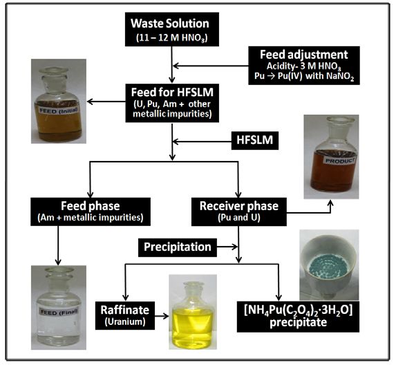
BARC/2021/E/004
BARC/2021/E/004

                                  GOVERNMENT OF INDIA
                              DEPARTMENT OF ATOMIC ENERGY

                  CLEAN METHODOLOGY FOR REMEDIATION OF ANALYTICAL
                      RADIOACTIVE WASTE BY RECOVERING Pu AND Am
                                                 by
                            Jisha S. Pillai and Satyajeet Chaudhury*
                                       saty@barc.gov.in*
                                      Fuel Chemistry Division
                            Seraj A. Ansari and Ashutosh Srivastava
                                     Radiochemistry Division

                          BHABHA ATOMIC RESEARCH CENTRE
                                  MUMBAI, INDIA
                                       2021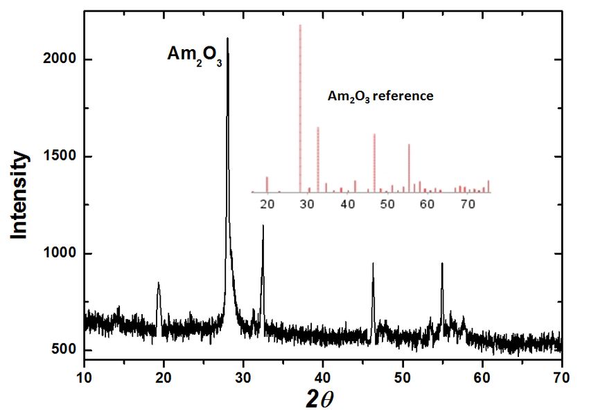
BARC/2021/E/004

              BIBLIOGRAPHIC DESCRIPTION SHEET FOR TECHNICAL REPORT
                                (as per IS : 9400 - 1980)

01   Security classification :    Unclassified

02   Distribution :               External

03   Report status :              New

04   Series :                     BARC External

05   Report type :                Technical Report

06   Report No. :                 BARC/2021/E/004

07   Part No. or Volume No. :

08   Contract No. :

10   Title and subtitle :         Clean methodology for remediation of analytical radioactive waste
                                  by recovering Pu and Am

11   Collation :                  18 p., 4 figs., 3 tabs.

13   Project No. :

20   Personal author(s) :         1. Jisha S. Pillai; Satyajeet Chaudhury
                                  2. Seraj A. Ansari; Ashutosh Srivastava

21   Affiliation of author(s) :   1. Fuel Chemistry Division,
                                  2. Radiochemistry Division,
                                  Bhabha Atomic Research Centre, Mumbai

22   Corporate author(s) :        Bhabha Atomic Research Centre, Mumbai - 400 085

23   Originating unit :           Fuel Chemistry Division,
                                  Bhabha Atomic Research Centre, Mumbai

24   Sponsor(s) Name :            Department of Atomic Energy

     Type :                       Government

                                                                                       Contd...
BARC/2021/E/004
30 Date of submission : March 2021
31 Publication/Issue date : April 2021
40 Publisher/Distributor : Head, Scientific Information Resource Division,
Bhabha Atomic Research Centre, Mumbai
42 Form of distribution : Hard copy
50 Language of text : English
51 Language of summary : English, Hindi
52 No. of references : 5 refs.
53 Gives data on :
Abstract : A clean methodology has been developed and demonstrated for the recovery of Pu
60
and Am from the radioactive analytical waste generated after chemical quality control of FBTR
fuel samples. With this methodology, pure Pu and Am are recovered individually leaving behind
alpha-free raffinate. The entire waste is processed in three stages: (i) Selective recovery of U
and Pu together with hollow fibre membrane technique leaving behind Am and other metallic
impurities in the raffinate, (ii) from the mixture of U and Pu obtained in stage (i), Pu was selectively
precipitated as ammonium plutonium(III) oxalate [NH4Pu(C2O4)2·3H2O], leaving most of
uranium in the supernatant solution, and (iii) Am from the raffinate is selectively recovered with
TODGA column chromatography. The raffinate after the recovery of actinides is free from
alpha activity (CLEAN METHODOLOGY FOR REMEDIATION OF ANALYTICAL
RADIOACTIVE WASTE BY RECOVERING Pu AND Am
Jisha S. Pillai1, Seraj A. Ansari2, Ashutosh Srivastava2 and Satyajeet Chaudhury*1
1
Fuel Chemistry Division,
2
Radiochemistry Division,
Bhabha Atomic Research Centre, Trombay, Mumbai - 400 085, India
*saty@barc.gov.in
Abstract
A clean methodology has been developed and demonstrated for the recovery of Pu and Am
from the radioactive analytical waste generated after chemical quality control of FBTR
fuel samples. With this methodology, pure Pu and Am are recovered individually leaving
behind alpha-free raffinate. The entire waste is processed in three stages: (i) Selective
recovery of U and Pu together with hollow fibre membrane technique leaving behind Am
and other metallic impurities in the raffinate, (ii) from the mixture of U and Pu obtained in
stage (i), Pu was selectively precipitated as ammonium plutonium(III) oxalate
[NH4Pu(C2O4)2·3H2O], leaving most of uranium in the supernatant solution, and (iii) Am
from the raffinate is selectively recovered with TODGA column chromatography. The
raffinate after the recovery of actinides is free from alpha activity (Pu तथा Am क� �ाि� �ारा िवश्लेषणात्मक रे िडयोस��य अपिशष्ट के
उपचार हेतु स्वच्छ ��या िविध
जीशा एस. िपल्लैa, िसराज ए. अन्सारीb, आशुतोष �ीवास्तवाb एवं सत्यजीत चौधरीa*
aइं धन रसायिनक� �भाग, भाभा परमाणु अनुसंधान क� �, मुंबई-400 085, भारत
bरे िडयो रसायिनक� �भाग, भाभा परमाणु अनुसंधान क� �, मुंबई-400 085, भारत
* : संबंिधत लेखक : ई-मेल : saty@barc.gov.in
सारांश
एफबीटीआर �धन नमून� के रासायिनक गुणता िनयं�ण के पश्चात उत्पा�दत रे िडयोस��य िवश्लेषणात्मक
अपिशष्ट म� से Pu एवं Am क� �ाि� हेतु एक स्वच्छ ��यािविध का िवकास एवं िनदशर्न �कया गया है। इस
��यािविध के माध्यम से अल्फा-मुक्त रै �फनेट को अलग करके िवशु� Pu एवं Am को अलग-अलग �ाप्त �कया
जाता है। पूरे अपिशष्ट को तीन चरण� म� ��िमत �कया जाता है । (i) रै �फनेट म� Am एवं अन्य धाित्वक अशुि�य�
को अलग करके खोखली फाइबर िझल्ली तकनीक के माध्यम से U एवं Pu क� एक साथ चयनात्मक �ाि�, (ii)
चरण (i) म� �ाप्त U और Pu के िम�ण से प्लावी िवलयन म� अिधकांश यूरेिनयम को छोडते �ए, Pu को
अमोिनयम प्लूटोिनयम (III) ऑक्सालेट [NH4Pu(C2O)23H2O] के �प म� चयनात्मक �प से प�रक्षेिपत �कया
गया, तथा (iii) TODGA कॉलम �ोमैटो�ाफ� के �ारा रै �फनेट से Am क� चयनात्मक �ाि� क� जाती है।
ऐिक्टनाइड� क� �ाि� के बाद रै �फनेट अल्फा स��यता (0.37 Bq/mL) से मुक्त होता है िजसका आसानी से
�ाबंधन �कया जा सकता है। इसके अलावा, �ाप्त ऐिक्टनाइड उत्पाद पुन:च�ण हेतु वांिछत शु�ता का होता है।
िनद�शर्त ��यािविध अवक्षेपण/आयन-िविनमय तकनीक क� तुलना म� ती� है, इसके �ारा कायर्स्थल पर
कमर्चा�रय� को कम िव�करण उ�ासन �ाप्त होता है एवं कम मा�ा म� ि�तीयक अपिशष्ट उत्पन्न होता है।
�मुख शब्द : नािभक�य अपिशष्ट; एिक्टनाइड� का पृथक्करण ; TODGA ; खोखली फाइबर िझल्ली ;
एिक्टनाइड ।CONTENT 1. INTRODUCTION .................................................................................................... 1 2. EXPERIMENTAL PROCEDURE ............................................................................ 2 2.1. Preparation of Feed for U/Pu Separation ................................................................... 2 2.2. Hollow Fibre Membrane Separation .......................................................................... 2 2.3. Precipitation of Pu .................................................................................................... 3 2.4. Recovery of Am by TODGA Column ....................................................................... 4 3. RESULTS AND DISCUSSION ................................................................................ 5 3.1. Separation of U and Pu by Hollow Fibre Membrane ................................................ 5 3.2. Selective Precipitation of Pu Over U ......................................................................... 6 3.3. Recovery of Am by TODGA Column ....................................................................... 6 3.4. Precipitation of Am .................................................................................................... 7 4. CONCLUSION .......................................................................................................... 9 ACKNOWLEDGEMENT ..................................................................................................... 9 REFERENCES ...................................................................................................................... 10
List of Figures
   Fig. No.                              Title                                Page
   Fig.1       (a) Hollow fibre module, (b) Flow pattern in module, and   3
               (c) Schematic representation of the HFSLM set-up
   Fig.2       Flow diagram for the processing of Pu bearing waste        4
               solution
   Fig.3       Column set-up for Am separation                            5
   Fig.4       XRD pattern of americium oxide                             7

                                   List of Tables
Table No.                                  Title                               Page
Table.1       Composition of the actual laboratory waste used and analytical 8
              results of various metallic impurities at different stages of
              separation
Table.2       Specifications of hollow fibre membrane contactor              8
Table.3       Decontamination factor of various metallic ions during 9
              separation of plutonium
1. INTRODUCTION
As a part of chemical quality control of Fast Breeder Test Reactor (FBTR) fuel samples, large
volumes of analytical radioactive waste are generated in our laboratory. In the laboratory, the
fuel samples are received as solid (U/Pu)-carbide which is dissolved in acid for chemical
analysis. The waste solution after analysis (analytical waste) and un-used sample solution is
then collected as nuclear laboratory waste. About 0.5 L of such waste is generated every
month in our laboratory which needs treatment before its safe disposal. Since these wastes
contain actinides such as Pu (2 – 5 g/L), U (2 – 5 g/L) and Am (20 – 30 mg/L) in different
composition (depending upon the type of the fuel and its age), they are extremely hazardous
to the environment. Additionally, the waste also contains inactive process chemicals like Na,
Ti, Fe, Ag and Cr etc. along with actinides. Since the half-lives of alpha emitting actinides
(particularly, 241Am, 243Am, 239Pu and 238Pu) are in hundreds of years, disposal of waste
containing these actinides possesses a challenge from environmental safety considerations.
However, if actinides are removed from it, the residual waste can be managed safely at very
low risk and at a reduced cost. Additionally, Pu being an important nuclear material
(primarily 239Pu which is fissile), its accounting is necessary from Nuclear Material
Accounting (NUMAC) point of view. Also, the recovery of actinides (particularly, Pu and
Am) from the waste has an added advantage from the “wealth from waste” belief.
In the literature, several methods can be found for the separation and purification of Pu from
analytical laboratory wastes [1]. The most widely used method in our laboratory is the
precipitation, where Pu and Am are precipitated as oxalate, and U is left in the raffinate [2].
However, one of the main drawbacks of precipitation method is the huge loss of Pu and Am
in the supernatant (mg level) and lower purity of the product that necessitates several cycles
of operation. Apart from this, Am(III) is also co-precipitated along with Pu(III) that requires
an additional step for their mutual separation. Therefore, the conventional precipitation
method is considered as very tedious due to several purification steps, and associated risk of
radiation exposure to the working personnel. The risk of radiation exposure becomes higher
while working with the waste containing higher percentage of 241Am which a major source of
gamma radiation. In this context, we developed a simple and clean methodology for the
treatment of laboratory waste where Pu and Am are quantitatively recovered individually in
desired purity with the raffinate free from all actinides.
In this communication, we report a clean methodology for the recovery of Pu and Am from
the radioactive analytical waste generated during the chemical quality control of FBTR fuels.
The entire waste treatment is done in three stages. Stage-I: Recovery of U and Pu by Hollow
Fibre Supported Liquid Membrane (HFSLM). Stage-II: Mutual separation of U and Pu by
precipitation, Stage-III: Recovery of Am by chromatography column. Following this method,
several litres of laboratory waste has been processed and several grams of Pu were recovered.
The novelty of this work lies in its ease of operation without risk of personnel radiation
exposure, and a clean separation that gives a complete solution for the treatment of nuclear
laboratory waste.
12. EXPERIMENTAL PROCEDURE 2.1. Preparation of Feed for U/Pu Separation The mixed U/Pu carbide FBTR fuel samples, received for chemical quality control, are the main source of nuclear analytical laboratory waste. The solid sample is dissolved by refluxing in a mixture of (1:1) concentrated HNO3/H2SO4. Heating with only concentrated HNO3 is avoided due to incomplete dissolution and it also leads to the formation of organic acids like oxalic acid and maleic acid, which interfere in the analysis of U and Pu by electroanalytical methods. Since the boiling point of H2SO4 is above 300˚C, it acts as a sink and dissolves the sample instantaneously without forming the organic acids. This method of dissolution is fast and gives clear solution ready for analysis. After analysis, the analytical waste and the left over dissolved fuel sample are collected as analytical waste. To the waste solution containing U, Pu and Am along with other metallic impurities at about 10 M HNO3, calculated amount of 0.1 M HNO3 was added so as to bring the acidity of the solution to about 3.5 – 4.0 M HNO3. The composition of a typical analytical waste used in this work is given in (Table.1). Two litres of this solution was transferred into a 2.5 L capacity carboy for HFSLM separation. The valency of Pu in this solution was adjusted to Pu(IV) by adding 10 g of NaNO2 in the carboy. The final solution after valency adjustment was at 3.7 M HNO3 which was used as feed for the separation of U and Pu by HFSLM. 2.2. Hollow Fibre Membrane Separation Hollow fibre module was made up of 10,000 hydrophobic microporous polypropylene hollow fibers enclosed in a polypropylene shell of 2.5”x8” dimension. Detail specification of the module is given in (Table.2). The HFSLM was prepared by pumping ligand solution (30% TBP / n-dodecane) through lumen side of the module at a pressure of ~20 kPa in recirculation mode. To ensure the complete soaking of the membrane pores, the ligand solution was circulated for ~15 minutes when it started percolating from lumen side to the shell side. The excess of ligand solution was washed out completely by passing distilled water from both the sides (lumen side and shell side) prior to the introduction of the feed and receiver solutions. The HFSLM thus prepared was used for the separation of U and Pu from the waste. For the entire procedure, the feed solution was passed through the lumen side while the receiver solution was passed through the shell side of the module at a flow rate of 300 mL/min. A schematic diagram showing the HFSLM transport is shown in (Fig.1). 2
Fig.1. (a) Hollow fibre module, (b) Flow pattern in module, and (c) Schematic
       representation of the HFSLM set-up.

2.3. Precipitation of Pu
The product received from HFSLM separation (U and Pu) was diluted with 0.1 M HNO3 so
as to make the final acidity of 1 M. The Pu valency in this solution was Pu(III) which was
directly precipitated by adding saturated oxalic acid solution. After adding oxalic acid, the
solution was stirred to get greenish colour [NH4Pu(C2O4)2·3H2O] precipitate. The precipitate
was filtered, dried and heated at 450°C to get PuO2 powder. A flow diagram for the
processing of waste solution is shown in (Fig.2).

                                                                                           3
Fig.2. Flow diagram for the processing of Pu bearing waste solution. 2.4. Recovery of Am by TODGA Column Extraction chromatography resin was prepared by impregnating TODGA on chromosorb-W as described earlier [3]. A known amount of TODGA (about 50 g) was dissolved in sufficient quantity of acetone in a 1000 mL stoppered conical flask. To this flask, an equal weight of previously washed and dried chromosorb-W was added. The slurry was then equilibrated for 24 hours in a mechanical shaker. After equilibration, the solvent (acetone) was removed by flushing nitrogen gas with gentle stirring. The resultant resin material was dried in vacuum at 80 – 90o C to a constant weight. The weight percentage of the TODGA loaded on the resin, calculated from the weight gain of the resin before and after impregnation, was found to be ~50% w/w. The chromatography column was prepared by packing 72 g of TODGA resin in a 2.8 cm diameter glass column having suitable standard joints for connecting to the vacuum. The bed height of the column was 25 cm with a bed density of 0.47 g/cm3. This column was set-up in a glove box (Fig.3.), and the flow rate was adjusted to ~5 mL/min with the help of external fume hood suction. The column was preconditioned by passing two bed volumes of 1.5 M HNO3 before passing the actual waste solution. The raffinate solution leftover after separation of U and Pu (containing entire Am and other metallic impurities) was directly passed through TODGA column where Am(III) was selectively held on the column. Finally, the loaded Am(III) from the column was eluted with 0.01 M EDTA. The entire Am(III) solution eluted from the column (in about 1.5 L) was evaporated under IR lamp to reduce its volume to about 300 mL, and Am(III) from this solution was precipitated as Am/oxalate. 4
Fig.3. Column set-up for Am separation

3. RESULTS AND DISCUSSION
3.1. Separation of U and Pu by Hollow Fibre Membrane
The separation of U and Pu was carried out with 30% TBP as the carrier in HFSLM. The
separation was based on the principle that TBP can complex only with U(VI) and Pu(IV)
at 3 – 4 M HNO3, but not Pu(III) or Am(III) and other metallic impurities present in the
waste. On the other hand, the extracted U(VI) and Pu(IV) from the TBP phase can be stripped
by complexing with ammonium sulphate, and by reducing Pu(IV) to Pu(III). By following
this fundamental principle, the feed solution for HFSLM was kept at 3 – 4 M HNO3 and Pu
valency in the feed was adjusted to Pu(IV). Similarly for efficient stripping of Pu and U in the
receiver phase, a mixture of complexing and reducing solution containing 2 M (NH4)2SO4 +
0.5 M Hydrazine hydrate + 0.5 M Hydroxyl amine dissolved in distilled water was employed.

A typical 2.0 L of waste solution (Table.1) containing 2.67 g/L Pu(IV), 1.98 g/L U(VI) and
26.2 mg/L Am(III) at 3.7 M HNO3 was used as feed for TBP-HFSLM run. The receiver
solution was 0.5 L complexing solution. Though the strip solution was made in water, its
acidity reached to 3 M HNO3 after 30 minutes due to co-transport of acid from feed to
product side. After 30 minutes, the feed and receiver phase acidity became
equal (3 M HNO3), which restricted further co-transport of acid and this equilibrium
remained constant throughout the HFSLM operation. After 3 h of HFSLM run, >99% Pu and
U were transported into the receiver phase with
step in the Pu recovery where ammonium plutonium oxalate precipitate is converted into PuO2. After precipitation, the Pu/oxalate solid was dried and calcined at 450o C to get PuO2 powder. The choice of using optimized composition of receiver phase (2 M NH4)2SO4 + 0.5 M Hydrazine hydrate + 0.5 M Hydroxyl amine) in HFSLM has two important role. Firstly, it helps in the stripping by reducing Pu to Pu(III), and by complexing U and Pu with sulphate. Secondly, this composition also helps in the final oxalate precipitation of Pu(III). 3.2. Selective Precipitation of Pu Over U It should be noted that the selective precipitation of Pu over U is carried out at 1 M HNO3 in the presence of 0.5 M ammonium sulphate and ascorbic acid [2]. In the conventional precipitation method, 0.05 M ascorbic acid is added to the feed to reduce Pu to Pu(III) followed by addition of saturated oxalic acid solution when Pu(III) is selectively precipitated as ammonium plutonium oxalate [NH4Pu(C2O4)2·3H2O]. In the present work, our choice of using hydrazine hydrate and hydroxyl amine as reductant in the strip solution of HFSLM was to avoid additional use of reductant at precipitation stage. In the present work, therefore, the product received from the HFSLM separation stage (U and Pu) was diluted with 0.1 M HNO3 to make the final acidity of 1 M and Pu(III) was directly precipitated by adding saturated oxalic acid solution. As shown in (Table.3), excellent decontamination factor was recorded after precipitation cycle. 3.3. Recovery of Am by TODGA Column The leftover Am(III) and other metallic impurities present in the raffinate after HFSLM separation step was further processed to separate Am(III) by TODGA chromatography column. The separation of Am was carried out from a typical 2.0 L leftover raffinate in HFSLM separation containing 26.2 mg/L Am. (Table.1) gives the composition of the waste before and after U/Pu separation by HFSLM. Here, the concentrations of Am and other metallic impurities in the waste decreased by ~1.4 times after the separation of U and Pu. This is due to dilution of the waste from HFSLM washings collected in the same container (after its operation). At this stage, the feed acidity of the Am containing waste solution was 1.5 M HNO3. The separation of Am(III) from the acidic feed by TODGA column was based on the excellent complexation ability of diglycolamide ligands for trivalent actinides over other metallic impurities [4]. The feed solution was passed through the column at a flow rate of 5 mL/min where Am(III) was quantitatively held on the column. The entire raffinate (about 2.5 L) was collected in a single container and analyzed for Am and other metallic impurities. As summarized in (Table.1), the Am loss in the raffinate was < 1 µg/L. On the other hand, all the other metallic impurities were entirely present in the raffinate indicating that none of them were held on the column. The gross alpha activity of the raffinate collected from the column was about 110 Bq/L, which corresponded to ~0.87 g/L of 241Am. This raffinate was sent as low level liquid waste for final treatment and disposal at waste management facility. After loading the Am(III) on the TODGA column, it was washed with another 1 L of 6
1.5 M HNO3 to remove any entrapped impurities. After washing, the entire Am was eluted
with 1.5 L of 0.01 M EDTA. Reason for using EDTA as an eluent was based on our reported
work [5], where it has been shown that the loaded metal ion can be efficiently eluted with a
complexing solution as dilute acid gave a long tailing in the elution curve. The purity of the
Am product was found to be >99% as certified by alpha & gamma spectrometry for Am, and
ICP-AES analysis for non-radioactive elements. Finally, the Am from the product solution
was quantitatively precipitated as americium oxalate.

3.4. Precipitation of Am
Before precipitation of Am from the product solution, it was necessary to remove EDTA in
the solution, which otherwise may interfere during the Am/oxalate precipitation due to its
strong complexing ability. Additionally, presence of EDTA in the Am/oxalate precipitate will
also impart organic impurities in the final product. To remove EDTA from the solution,
concentrated nitric acid was added so as to make the final acidity ~1 M HNO3 which lead to
the precipitation of EDTA. This solution was filtered through Whatman® 42 filter paper (pore
size 2.5 µm) to remove EDTA. The precipitate was washed with 1 M HNO3 to recover the
entire Am. To the clear filtrate solution (about 400 mL) containing Am, 3 g of ascorbic acid,
25 g of ammonium sulphate and about 80 mL saturated oxalic acid solution was added with
constant stirring to get americium oxalate precipitate. After settlement of the precipitate,
supernatant solution was decanted carefully. Gross alpha counting of the supernatant solution
ensured the quantitative precipitation of Am. This precipitate containing Am was filtered
through Whatman® 41 filter paper (pore size 20 µm), washed with 1:1 mixture of 1 M HNO3
and 0.2 M oxalic acid. Finally, the precipitate was carefully transferred into alumina boat and
heated in a muffle furnace at 700°C to get black coloured Am2O3 powder. As shown in
(Fig.4), the XRD pattern of the Am2O3 was matching with that of standard XRD data,
confirming the formation of Am2O3 powder.

                         Fig.4. XRD pattern of americium oxide.

                                                                                             7
Table.1. Composition of the actual laboratory waste used and analytical results of
various metallic impurities at different stages of separation
Feed before U/Pu Feed after U/Pu Raffinate after Am
Element
separation separation loading on column
U 1.98 g/LTable.3. Decontamination factor of various metallic ions during separation of
plutonium
Decontamination factor for Pu fraction*
Element Feed Conc.
After HFSLM After precipitation
U 1.98 g/L 1.8 160
Am 26.2 mg/L 2620 104
Fe 1.65 mg/L 4930 104
Cr 37.4 mg/L 2370 105
Mo 7.48 mg/L 2815 104
Al 1.48 mg/L 1890 104
Ni 173 mg/L 2150 104
Cu 0.24 mg/L 2340 105
*Decontamination factor was calculated as the ratio of the concentration of impurity in the
feed to that of its concentration in the product.
4. CONCLUSION
A simple and clean two stage separation method was developed for quantitative recovery of
Pu and Am individually from the laboratory waste. In the first stage, U and Pu are recovered
by hollow fibre membrane, followed by selective Pu precipitation and conversion to PuO2
powder. In the second stage, the Am from the leftover raffinate is recovered by column
chromatography. The final raffinate after the recovery of entire actinides is almost free from
alpha activity and is easy for handling as low level liquid waste. The idea of complete
recovery of actinides from the waste (waste free from alpha activity) would help in the final
radioactive waste management as it will reduce the alpha radiation load to the solid waste
blocks (radioactive liquid waste is converted into solid glass matrix for geological burial).
Apart from the waste management aspects, the recovered actinides have several potential
applications, and may be considered as “wealth from waste”.
ACKNOWLEDGEMENT
The authors are thankful to Dr. P.K. Pujari, Associate Director, RC&I Group of BARC, and
Dr. S. Kannan, Head, Fuel Chemistry Division for their keen interest in this work.
9REFERENCES
[1] Baron, P. et al. “A review of separation processes proposed for advanced fuel cycles
based on technology readiness level assessments”, Progress in Nuclear Energy,
117:Article 103091, 2019.
[2] Sali, S.K. et al. “A novel methodology for processing of plutonium-bearing waste as
ammonium plutonium(III)-oxalate”, Nuclear Technology, 151(3):289-296, 2005.
[3] Ansari, S.A. et al. “Extraction chromatographic studies of metal ions using N,N,N,N-
tetraoctyl diglycolamide as the stationary phase”, Talanta, 68(4):1273-1280, 2006.
[4] Ansari, S.A. et al. “Chemistry of diglycolamides: Promising extractants for actinide
partitioning”, Chemical Reviews, 112(2):1751-1772, 2012.
[5] Ansari, S.A. and Mohapatra, P.K. “A review on solid phase extraction of actinides and
lanthanides with amide based extractants”, Journal of Chromatography A, 1499:1-20,
2017.
10You can also read