Corner Design For All Users - A review of geometric design practices to improve safety for pedestrians and bicyclists at intersection corners ...
←
→
Page content transcription
If your browser does not render page correctly, please read the page content below
PERSPECTIVES IN PRACTICE

Corner Design For All Users
A review of geometric design practices to improve safety for
pedestrians and bicyclists at intersection corners

SUMMARY
Historically, intersections have been designed to facilitate easy turning by infrequent design vehicles. This approach has
resulted in countless intersections that are much larger than they need to be; intersections where pedestrians and bicyclists
confront long crossings that leave them exposed to turning vehicle traffic moving quickly along large corner radii. Balancing
access for more infrequent larger vehicles with the safety needs of vulnerable roadway users is possible and cities across
North America have been experimenting with designs for years. This white paper makes the case, with case study examples,
for a more thoughtful approach to intersection corner design as communities place greater priority on reducing serious
injuries and deaths among vulnerable road users.

Contributors:

Joe Gilpin, Vice-President
Matt Pinder, Senior Designer
Kristi DiCocco, P.E. Senior Engineering Associate
Derek Abe, Planning Associate
Nataliya Pekar, Engineer in Training

ALTA

                                   As a global leader in mobility innovation
                                  for over 22 years, Alta helps make positive
                                    changes in communities to empower all
                                     people to live active, healthy lives. We
                                     are dedicated to connecting people to
                                   places by working across disciplines and
                                  scale to address social equity, access, and
                                           environmental resilience.

© Alta Planning + Design, 2020.

Corner Design for All Users by Alta Planning + Design is licensed under a Creative Commons Attribution-NoDerivatives 4.0 International License.

Disclaimer: The design details, recommendations and conclusions in this document are based on interviews with city staff throughout North
America, Alta project experience, and industry design guidance. This white paper uses design resources and discoverable original research by
various institutions to make conclusions, though it is possible that other research that may be relevant was not identified. Engineering judgment
should always be used in roadway design decisions.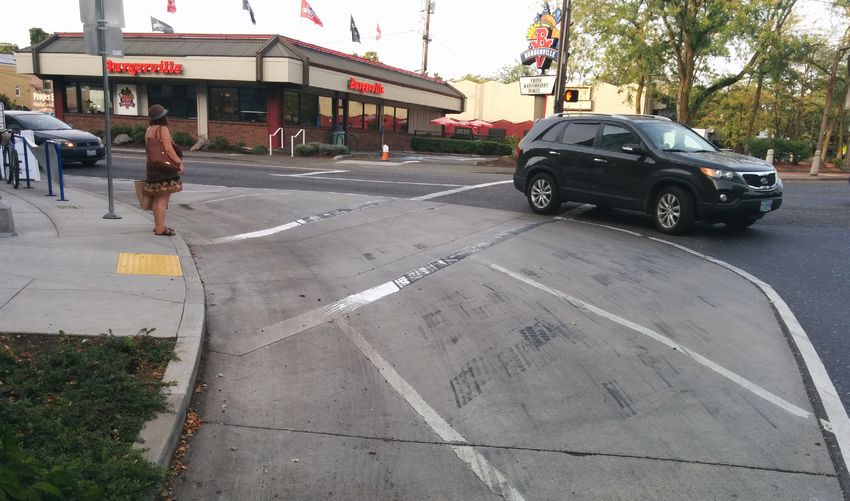
CONTENTS

01 INTRODUCTION .  .  .  .  .  .  .  .  .  .  .  .  .  .  .  .  .  .  .  .  .  .  .  .  .  . 5
       Background  . . . . . . . . . . . . . . . . . . . . . . . . . . . . . . . . . . . . . . . . . . . . . . 5
       Engineering Basis  . . . . . . . . . . . . . . . . . . . . . . . . . . . . . . . . . . . . . . . . . 5
       Relationship between Radius and Speed . . . . . . . . . . . . . . . . . . . . . 6
       Physical vs Effective Radius  . . . . . . . . . . . . . . . . . . . . . . . . . . . . . . . . 8
       Relationship between Stopping Sight Distance and Speed . . . . . 8
       Pedestrian Risk  . . . . . . . . . . . . . . . . . . . . . . . . . . . . . . . . . . . . . . . . . . 10
       Pedestrian Exposure . . . . . . . . . . . . . . . . . . . . . . . . . . . . . . . . . . . . . . 11
       Other Factors . . . . . . . . . . . . . . . . . . . . . . . . . . . . . . . . . . . . . . . . . . . . 12
       Conclusion . . . . . . . . . . . . . . . . . . . . . . . . . . . . . . . . . . . . . . . . . . . . . . 13

02 CORNER DESIGN  .  .  .  .  .  .  .  .  .  .  .  .  .  .  .  .  .  .  .  .  .  .  .  . 15
       Design Objectives . . . . . . . . . . . . . . . . . . . . . . . . . . . . . . . . . . . . . . . . 15
       Typical Applications . . . . . . . . . . . . . . . . . . . . . . . . . . . . . . . . . . . . . . 15
       Vehicle Accommodation  . . . . . . . . . . . . . . . . . . . . . . . . . . . . . . . . . . 16
       Design Variables  . . . . . . . . . . . . . . . . . . . . . . . . . . . . . . . . . . . . . . . . . 17

03 POLICY SUPPORT .  .  .  .  .  .  .  .  .  .  .  .  .  .  .  .  .  .  .  .  .  .  .  . 25
       Local Agency Examples . . . . . . . . . . . . . . . . . . . . . . . . . . . . . . . . . . . 25
       State/Provincial Examples  . . . . . . . . . . . . . . . . . . . . . . . . . . . . . . . 25

04 RECOMMENDATIONS  .  .  .  .  .  .  .  .  .  .  .  .  .  .  .  .  .  .  .  . 27
       Identify Vehicles  . . . . . . . . . . . . . . . . . . . . . . . . . . . . . . . . . . . . . . . . . 27
       Define Turning Paths . . . . . . . . . . . . . . . . . . . . . . . . . . . . . . . . . . . . . . 27
       Select Materials . . . . . . . . . . . . . . . . . . . . . . . . . . . . . . . . . . . . . . . . . . 27
       Monitor Results . . . . . . . . . . . . . . . . . . . . . . . . . . . . . . . . . . . . . . . . . . 27

05 CASE STUDIES  .  .  .  .  .  .  .  .  .  .  .  .  .  .  .  .  .  .  .  .  .  .  .  .  . 29
       Agencies Consulted  . . . . . . . . . . . . . . . . . . . . . . . . . . . . . . . . . . . . . . 29
       Mississauga, Ontario, Canada  . . . . . . . . . . . . . . . . . . . . . . . . . . . . . 30
       St. Louis Park, Minnesota . . . . . . . . . . . . . . . . . . . . . . . . . . . . . . . . . 32
       New York City, New York . . . . . . . . . . . . . . . . . . . . . . . . . . . . . . . . . . . 34
       Austin, Texas . . . . . . . . . . . . . . . . . . . . . . . . . . . . . . . . . . . . . . . . . . . . 36
       San José, California  . . . . . . . . . . . . . . . . . . . . . . . . . . . . . . . . . . . . . . 38
       Portland, Oregon  . . . . . . . . . . . . . . . . . . . . . . . . . . . . . . . . . . . . . . . . 40
       Atlanta, Georgia . . . . . . . . . . . . . . . . . . . . . . . . . . . . . . . . . . . . . . . . . . 42
       Bend, Oregon . . . . . . . . . . . . . . . . . . . . . . . . . . . . . . . . . . . . . . . . . . . . 44

06 ENDNOTES  .  .  .  .  .  .  .  .  .  .  .  .  .  .  .  .  .  .  .  .  .  .  .  .  .  .  .  . 47

                                                                                                             CORNER DESIGN FOR ALL USERS | 3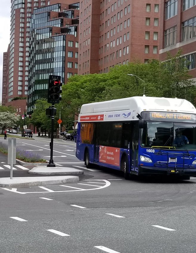
Minneapolis, MN

4 | ALTA PLANNING + DESIGN
01 INTRODUCTION
This white paper explores the relationship between intersection corner design and pedestrian and bicyclist safety.
Intersection design often involves balancing the needs of larger design vehicles with standards that sometimes conflict
with pedestrian and bicycle safety. This white paper outlines the inherent conflicts that exist between turning vehicles and
pedestrians/bicyclists, explores the design challenges, and catalogs solutions and lessons learned from cities across the US
and Canada.

Background
Cities in the US and Canada have long recognized the
relationship between vehicle speed and crash severity for
vulnerable road users and many have attempted a variety
of solutions to manage this conflict. The inherent problem
in intersection design is the need to accommodate a large
design vehicle, often a semi truck or large emergency
vehicle, through a tight right turn or a left turn (from a
one-way street). Designing such corners often has the
following results:                                              Crashes between pedestrians and right turning vehicles are
                                                                a common pedestrian crash type in most US and Canadian
• Large vehicles, which compose a small fraction of             communities.
  roadway traffic, are typically provided large corner radii
  to complete their turns
                                                                Engineering Basis
• Large corner radii can substantially lengthen pedestrian
  crossings and exposure to vehicular traffic                   The following section explores design considerations in
                                                                the geometric design of an intersection corner radius.
• Large corner radii enable smaller passenger vehicles,
                                                                This section is intended to be technical and utilize North
  which compose the vast majority of roadway traffic, to
                                                                American geometric design guidance and industry technical
  make turns at higher speeds
                                                                research to link corner radii size with implications for
• At higher vehicle turning speeds,                             drivers and pedestrians. The AASHTO A Policy on Geometric
                                                                Design of Highways and Streets 2018 Edition (“Green Book”)
  • Driver reaction time and stopping distance require
                                                                supports the findings of this white paper and provides in
    more space
                                                                section 9.6.1.4 general recommendations for curb radii of:
  • The likelihood of a driver yielding to crossing
    pedestrians and/or bicyclists is lower                      • as low as 15 feet (5 meters) to accommodate passenger
                                                                  vehicles
  • Potential for crashes with pedestrians and bicyclists is
    higher with an increased likelihood of injury or death      • 40 feet (12 meters) or more to fit the paths of large trucks
    to the non-motorized user                                     or buses

These relationships will be explored in detail along with       This section explores common engineering principles and
various design and policy solutions which will allow large      guidance to explore the relationships between minimum
vehicles to complete turns while improving the safety of        turn radius, stopping sight distance, and reaction time, as
pedestrians and bicyclists.                                     well as research on driver speed and yielding behavior in
                                                                varying conditions.

                                                                                                        CORNER DESIGN FOR ALL USERS | 5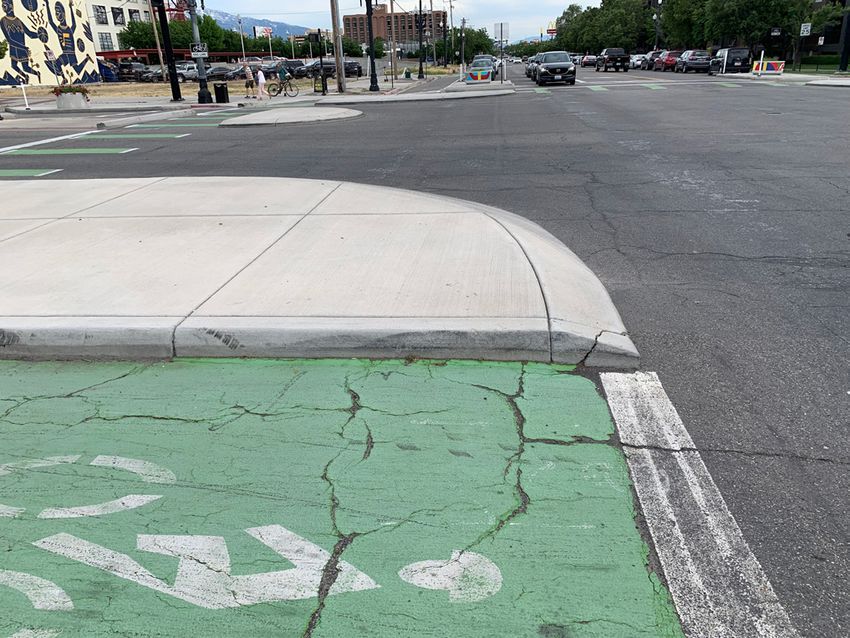
Relationship between Radius and Speed
       The relationship between radius and speed is determined                         reality, there will be some cross slope variation dependent
       by the balance of forces as a vehicle navigates a curve,                        on the amount of crowning present. Lateral friction factors
       where lateral friction results in a centripetal force, and                      (f) are dependent on a number of variables, including
       superelevation results in gravitational force. The 2018                         speed, roadway surface, and the type and condition of tires.
       AASHTO Green Book (Section 3.3.3.3) describes minimum                           Rmin for design is based on emax and fmax at the limits of what
       radius of horizontal curvature in design is derived from this                   is comfortable for most drivers. As such, lateral friction
       relationship and represented by the following equation                          factors recommended by AASHTO and TAC are conservative
       (Equation 3-8)2:                                                                relative to the capabilities of most modern vehicles in order
                                                                                       to ensure skidding is avoided. In urban scenarios, drivers are
                                                             (Imperial)                more likely to complete a turn with several stops due to the
                                                                                       nature of urban surroundings as opposed to at a constant
                                                                                       speed more common in suburban and rural settings.
                                                             (Metric)
                                                                                       Using superelevation as zero and design friction factors
       Where,
                                                                                       from AASHTO, the relationship between speed and curve
          emax - maximum rate of superelevation
                                                                                       radius is plotted in Figure 1. The equation is to the vehicle’s
          Fmax - maximum side friction factor
                                                                                       center of gravity. To compensate and estimate curb radii
          V - design speed mph (kph)
                                                                                       size, 7 feet (1.9 meters) has been subtracted.
          Rmin - radius of curvature ft (m)
                                                                                       The AASHTO equation in Figure 1 produces an estimate of
       The equivalent is found in the TAC GDGCR in Section 3.2.2.6
                                                                                       vehicle speed based on radius. A 2004 study by the Texas
       with Equation 3.2.3.
                                                                                       Transportation Institute17 looked at vehicle free flow speeds
       For the purpose of evaluating urban intersections,                              through channelized right turns and found that speed was
       superelevation is set to zero, as horizontal curves on                          rarely constant with general deceleration slightly past the
       low-speed streets are not substantially influenced by it. In                    midpoint of curvature and then acceleration towards the
                                                                                       exiting tangent. The study conducted speed observations in
                mph
                kph

                50 30

                40 25

                     20
                30
        Speed

                     15
                20
                     10

                10
                      5

                 0    0
                          0         20             40                   60                 80        100             120         140            160 ft
                          0     5           10               15              20             25       30         35         40          45        50 m
                                                                                  Radius
       Figure 1: Vehicle Speed vs. Horizontal Curve Radius

6 | ALTA PLANNING + DESIGN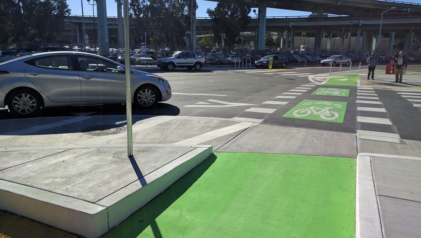
mph
          kph
          50 30

                             Beginning of Turn
          40 25
  Speed                                                                                             Middle of Turn

                20
          30

19 different
           15channelized turns with curb radii ranging from        The TexasAASHTO
                                                                              Transportation
                                                                                     Eq 3-8   Institute study also created
       20
27 feet (8 meters) to 86 feet (26 meters). Interestingly, as       equations to approximate the observed data which could
           10
shown in Figures   2 and 3, observed average midpoint curve        be utilized or modified in practice. Many of the variables
speeds matched closely with the AASHTO equation 3-8;               cited are unique to channelized right turn lanes. The
       10
            5
however, speeds    at the beginning of the curve were higher,      study did discuss the implications of the data on selecting
               20            30
as were 85th percentile speeds.            40 shows that
                                   This study            50the      60
                                                                   crosswalk      70
                                                                              locations,       80
                                                                                         suggesting  that the90middle of the
                                                                                                                          100 ft
AASHTO equation may represent    10 less than half of vehicles
                                                        15                  20 produce the lowest
                                                                   turn would                                             30 ma
                                                                                                  25turning speeds. Overall,
                                                                 Radius
traveling through a right turn at the midpoint of the curve,       designer could conclude from the study that in constant
with half of vehicles exceeding the predicted speeds. This         speed scenarios, vehicles are capable of higher turning
makes sense given the conservative friction inputs into the        speeds than the AASHTO equation would predict and
AASHTO equation.                                                   a extremely small turning radius would be needed to
                                                                   guarantee low turning speeds.
                mph
          kph

          50 30

          40 25              Beginning of Turn
  Speed

                                                                                                    AASHTO Eq 3-8
                20
          30

                15
          20                                                                      Middle of Turn
                10

          10
                 5
                      20     30           40          50           60            70            80              90         100 ft
                                    10               15                    20                       25                    30 m
                                                                 Radius
Figure 2: TTI Study Average Speeds
                mph
          kph

          50 30

                             Beginning of Turn
          40 25
                                                                                                    Middle of Turn
  Speed

                20
          30

                15                                                          AASHTO Eq 3-8
          20
                10

          10
                 5
                      20     30           40          50           60            70            80              90         100 ft
                                    10               15                    20                       25                    30 m
                                                                 Radius
Figure 3: TTI Study 85th % Speeds

                                                                                                            CORNER DESIGN FOR ALL USERS | 7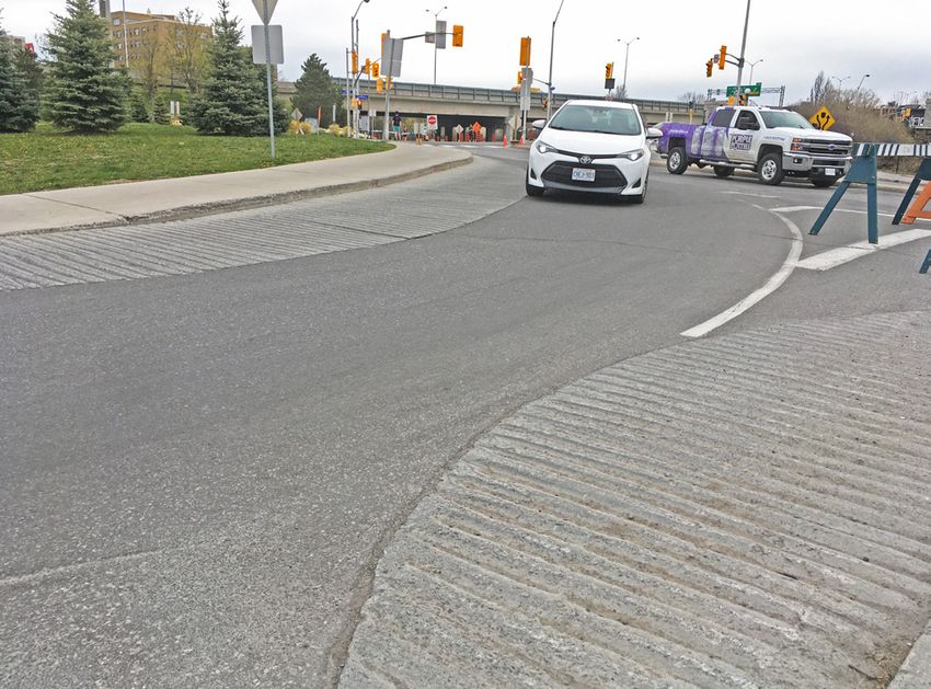
Physical vs Effective Radius
       There is a distinction between the physical corner radius        The stopping sight distance is a combination of distance
       and the effective radius that a vehicle can exploit given        until a driver reacts and begins to apply the brakes (braking
       other intersection factors11. This distinction is sometimes      reaction distance), and the distance required to stop after
       overlooked in street design and can further exacerbate           the brakes have been applied (braking distance). The
       the potential for high turning speeds through intersection       first component is dependent on reaction time. Reaction
       corners. The effective radius can vastly exceed the physical     times vary widely depending on factors associated with
       radius if features such as wide travel lanes, bicycle lanes,     the environment and the driver. For suburban, urban,
       or parking lanes exist that push the entry and receiving         urban core, and rural town contexts, a reaction time of 1.5
       travel lanes further away from the physical curb. Figure 4       seconds is used per AASHTO. Drivers are also expecting to
       illustrates some typical examples.                               decelerate at a turn in order to safely navigate and may start
                                                                        to decelerate regardless of the presence of an obstacle.
                                                                        Finally, while 11.2 ft/s2 is a comfortable/conservative
                                                                        deceleration rate used in design, most drivers decelerate at
                                                                        a rate greater than 14.8 ft/s2 when confronted with the need
                                                                        to stop for an unexpected object in the roadway (AASHTO).
                                                                        This is reflected below by equation and plotted in Figure 5.
                                                US
                                             DI                         This relationship can be plotted:
                                           RA DIUS
                                       E   RA
                             PHYSICAL IV
                                   CT

                                                                                                                  (Imperial)
                                 FE
                              EF

                                                                                                                  (Metric)

                                                                        Where,

                                                                            a - driver acceleration assumed at

       Figure 4: Effective corner radius examples
                                                                            t - perception-brake reaction time, assumed to be 1.5s
                                                                            V - initial speed, mph (kph)
       Relationship between Stopping Sight                                  d - stopping sight distance, ft (m)
       Distance and Speed                                               The equivalent is found in the TAC GDGCR in Section 2.5.3
                                                                        with Equation 2.5.2
       Stopping sight distance is the distance required along a
       roadway for a driver to identify and react to an obstacle        As Figure 5 illustrates, stopping distances vary considerably
       and to come to a complete stop in advance of the obstacle.       by speed. Figure 6 adds contextual visualization to this
       Drivers turning a corner at an intersection require clear        relationship and depicts where a vehicle would need
       sightlines and enough distance to come to a stop and             to start the reaction and braking processes at various
       yield to pedestrians and bicyclists (if applicable). At higher   speeds on approach to a right turn with a 25 foot or 7.4
       speeds, the distance required to stop safely increases. At       meter physical radius. Even speeds of 20mph (32kph) yield
       larger radii, the potential for increased speeds may result      distances that may be unrealistic for a driver to register the
       in insufficient distance to perceive and yield to pedestrians    need to stop for a pedestrian and be able to do so safely.
       given the greater distance covered during reaction time and
       braking.

8 | ALTA PLANNING + DESIGN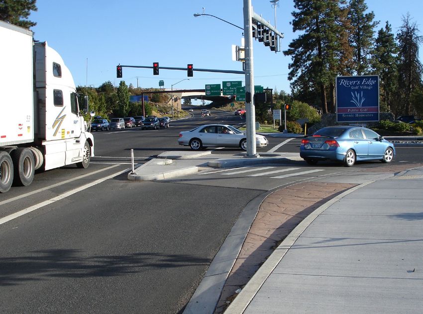
m

                               ft
                          50 160
                          45
                             140
                          40
                             120
Stopping Sight Distance

                          35                                                                                              Quick Reaction
                          30 100                                                                                          Time (1.5 sec)
                                        At 20mph (32kph), stopping sight distance is 70-82 ft (22-25m)
                          25   80
                          20
                               60                                                                                                                       Quick Reaction
                          15                                                                                                                            Time & Fast
                               40                                                                                                                       Deceleration
                          10
                               20
                           5
                           0    0
                                    0                    5                        10                            15                    20                              25 mph
                                    0           5              10               15                20                 25          30                35                 40 kph
                                                                                                 Speed
Figure 5: Stopping Sight Distance by Speed

                                25 mph 40 kph                       20 mph     32 kph                         15 mph 24 kph            10 mph 16 kph
                                                                       82 ft   25 m                                                      31 ft 9 m
                                  114 ft 35 m                                                                   54 ft 16 m                         8 mph 13 kph
                                                                                                                                                   24 ft 7 m

                                                                                        Uno
                                                                                                bstru
                                                                                                       cted
                                                                                                                                                         m

                                                                                                              View
                                                                                                                                                   9.8

                                               At a turn speed of 25mph (40kph), a motorist
                                                                                                                                                                               Yield Point
                                                                                                                                                ft,

                                               needs to detect a pedestrian 114 ft (35m)
                                                                                                                                            32

                                               before the yield point in order to safely stop
                                                                                                                                                              6m
                                                                                                                                           =

                                                                                                                                                           .
                                                                                                                                       g

                                                                                                                                                       t, 7
                                                                                                                                      Rc

                                                                                                                                                   f
                                                                                                                                                25
                                                                                                                                           R=

Figure 6: Stopping Sight Distance by Speed

                                                                                                                                                                   CORNER DESIGN FOR ALL USERS | 9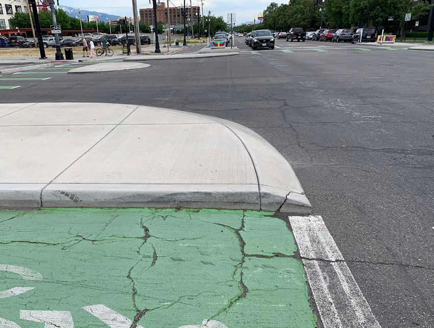
Pedestrian Risk
       Numerous studies have shown a direct correlation between                                                               100%
       vehicle speed and pedestrian crash severity. The probability
                                                                                                                                                                                       ry
       of a pedestrian being killed by a vehicle traveling at 20                                                                                                                     ju
                                                                                                                                                                                 If n
       mph (32 kph) is approximately 7 percent. At 32 mph (52                                                                                                                   o
                                                                                                                                                                           sk
                                                                                                                                                                         Ri
       kph) that probability increases to 25 percent, indicating                                                                     75%

                                                                                                                                                                                           ath
       the importance of minimizing vehicle speed at points of

                                                                                                                                                                                       f De
       potential conflict to improve pedestrian safety. Figure

                                                                                                                                                                                     ko
                                                                                                                                                                                  Ris
       7 displays the results of a 2011 study which normalized

                                                                                                                   Pedestrian Risk
       1990s data analysis from Presusse and Leaf12 to late 2000s                                                                    50%
       demographics1 with the shaded areas representing a 95
       percent confidence interval.

       There are multiple design guidance documents that
                                                                                                                                     25%
       equate the effective corner radius and potential for vehicle
       speed to pedestrian safety and exposure. FHWA has
       multiple publications that draw this reference including
       their PEDSAFE Countermeasure Selection System under
                                                                                                                              0%
       “Curb Radius Reduction”, the Signalized Intersections:                                                                mph 10          15    20   25       30     35          40       45   50     55         60
       Informational Guide7, and the Selecting Pedestrian Safety                                                             kph 15 20            30        40    50         60             70    80       90       97
       Improvements Library as a treatment for several types of
                                                                                                                  Figure 7: Pedestrian Risk of Injury or Death
       intersection related safety issues.

                                                                                                       X
                                                                                                                                                                                   SIDEWALK
                                                                   . 6 5’
                                                                       )
                                                                 (4 = 1
                                                                      m
                                                                    R
                                                       .6 ’
                                                     (7 2 5
                                                          )
                                                         m
                                                       R=
                                   )
                                  m
                                .2
                              15
                            ’(
                          50
                       R=

                                                        Crossing                                                                       Effective Turning               Vehicle Turning
           Curb Radius (R1)                                                              Crossing Time*
                                                       Distance (X)                                                                      Radius (R2)**                   Speed***
              15 ft (4.6 m)                           37 ft (11.3 m)                        10.6 seconds                                   41 ft (12.5 m)             14 mph (22.5 kph)
              25 ft (7.6 m)                           50 ft (15.2 m)                        14.3 seconds                                   52 ft (15.8 m)             16 mph (25.7 kph)
              50 ft (15.2 m)                          89 ft (27.1 m)                        25.4 seconds                                   74 ft (22.6 m)             18 mph (29.0 kph)
         *Assumes an average crossing speed of 3.5 fps (3.8 kph)
         ** Assumes the following widths: 6 ft (1.8 m) bike lane, 10 ft (3.0 m) travel lane, 7 ft (2.1 m) vehicle, 2 ft (0.6 m) clear from corner. R2 = v2/[15(F)], where F = 0.32, 0.31, and 0.29, respectively.
         *** Average speed in middle of turn

       Figure 8: Pedestrian Exposure vs Corner Radii

10 | ALTA PLANNING + DESIGN
Pedestrian Exposure
In addition to allowing pedestrians using the crosswalk A 2018 evaluation study of San Francisco’s first protected
to come into conflict with faster moving turning vehicles, intersection at 9th and Division Streets16, which features
large turning radii also increase the length of the crosswalk, mountable corner islands with passenger turning curb
which lengthens the time required for pedestrians to clear radii under 20 feet (6 meters), found that 100 percent of the
the intersection and increases their exposure to traffic observed motorists yielded when approaching a pedestrian
stress and potential conflict. and 96 percent yielded when approaching a bicyclist.
It should be noted that the entry legs of the protected
Driver Yielding Behavior intersection also featured raised crossings.
There has been substantial research into driver yielding Substantial work has been done exploring the performance
at uncontrolled intersections and mid-block crossings of pedestrian crossings at roundabouts, particularly
over the past several decades, which has been effectively interactions between visually impaired pedestrians
used to better understand countermeasures that affect and vehicles. Two studies9,14 have shown that driver
pedestrian safety and comfort in these contexts. The yielding behavior is much higher on roundabout entry,
condition that this white paper is analyzing is very different which functions more like a mid-block or perpendicular
in that it is examining vehicle right turns and their conflicts intersection-based crossing, than on roundabout exit.
with parallel pedestrian crossings. Roundabout exits are somewhat similar to right turns at
intersections in that the pedestrians are in a similar visual
Little existing literature is present that explores this subject
position and the driver is in the process of completing a
in detail, which is surprising given that right-turn pedestrian
right turn and accelerating out of it. Both studies found a
crashes are commonplace in North American communities.
correlation between vehicle speed and yielding; however,
A 2013 study on visually impaired pedestrians and driver other factors (see discussion in the next section), also
yielding looked at seven sites across the United States and generated considerable influence.
focused on driver yielding based on the positioning the
pedestrian took during the walk signal. Corner radius was
not discussed as a variable in the research; however, the
study did note in its conclusions that the authors found
“no relationships between curb configuration and drivers’
responses for yielding when making right turns at a green
traffic signal.”3 Vehicle speed was also not observed.
“Selecting a yield of 90% and the entrylane data from both roundabouts, we calculated that vehicles traveling at
18 mph had a positive predictive value of 0.89. Thus, using 18 mph as a cutoff speed for roundabout entry lanes, a
pedestrian could expect that approximately 9 out of 10 drivers would yield. By comparison, at the exit lane, the highest
calculated predictive value of 0.6 was associated with a vehicular speed of 10-11 mph. Unfortunately, even at this
relatively low speed, the pedestrian has only a 60% chance that a driver will yield. ”
CORNER DESIGN FOR ALL USERS | 11The 9th & Division Intersection has various corner designs featuring dual radius truck aprons created with striping and with raised concrete.
Credit: StreetsblogSF. Source article
Other Factors
There does seem to be a significant research gap in The preceding analysis focused on speed control through
understanding driver yielding and conflicts with pedestrians corner geometry. It should also be stated that geometry
during right turns at signalized intersections in the North alone is only one of several variables that can influence
American context. There are several international studies driver yielding and pedestrian safety at intersection
that do explore this issue, though the applicability is corners. Pedestrian assertiveness and pedestrian visibility
uncertain due to differences in driver culture, training, and are two other key variables which have been shown to
pedestrian behavior. Still, one study done in Shanghai strongly influence driver yielding behavior under a variety of
China in 201119 found that the number of conflicts between crossing conditions. One 2020 study4 on mid-block crossing
right-turning drivers and pedestrians could be expected yielding behavior even suggests that the higher the retail
to be lower with tighter corner radii. Conflicts were also value of the vehicle, the lower the driver was observed
observed to be dependent on the relative flows of vehicles to yield to pedestrians. Intersection designs which put a
and pedestrians. waiting pedestrian in a highly visible location or provide a
head start either through geometry or through tools like a
Leading Pedestrian Interval (LPI) will also improve yielding
behavior and reduce the chance for a crash that could
cause serious and fatal injuries.
12 | ALTA PLANNING + DESIGNTable 1: Summary of Variables
EFFECTIVE AVG VEHICLE 85TH% VEHICLE STOPPING SIGHT RISK OF SEVERE RISK OF
R ADIUS* SPEED** SPEED*** DISTANCE INJURY**** DEATH****
10 ft 3m 10 mph 16 kph 12 mph 19 kph 32 ft 9.8m 2-7% 1-4%
15 ft 4.5m 11 mph 18 kph 13 mph 21 kph 36 ft 11m 2-8% 1-4%
20 ft 6m 12 mph 19 kph 14 mph 23 kph 40 ft 12m 3-8% 1-4%
25 ft 7.6m 13 mph 21 kph 14.5mph 23 kph 45 ft 13.7m 4-9% 1-5%
30 ft 9m 14 mph 23 kph 15 mph 24 kph 50 ft 15.2m 5-11% 1-5%
40 ft 12m 15 mph 24 kph 16.5 mph 27 kph 55 ft 16.8m 6-13% 2-5%
50 ft 15.2m 16 mph 26 kph 17.5 mph 28 kph 60 ft 18.3m 7-15% 3-6%
60 ft 18.2m 17 mph 27 kph 18.5 mph 30 kph 65 ft 19.8m 8-18% 3-7%
70 ft 21.3m 18 mph 29 kph 19 mph 31 kph 71 ft 21.6m 10-20% 3-8%
80 ft 24.4m 19 mph 31 kph 20 mph 32 kph 77 ft 23.5m 13-21% 4-8%
95 ft 29m 20 mph 32 kph 21 mph 34 kph 82 ft 25m 14-22% 5-9%
*Not physical radius, this is the inside turning path of the vehicle
**Average speed expected through AASHTO Eq 3-8
***85th Percentile speed expected through data interpolation from TTI Study
****Estimated risk of injury or death from average turning speed
Conclusion
The preceding sections reviewed a number of engineering • Stopping sight distance for vehicles approaching a turn
factors and industry studies. These have shown: may not provide sufficient opportunity for a driver to
yield at even moderate speeds (20mph / 32kph)
• Average cornering speeds in the middle of the turn
roughly equate to the AASHTO horizontal curve • Smaller effective radii will reduce pedestrian exposure
equation; however, roughly half the vehicles will exceed and crossing time
this speed
• Driver yielding behavior to pedestrians is complex, but it
• Smaller effective turning radii will result in lower does show correlation to speed as one variable
expected turning speeds
Based on these findings, it is reasonable to conclude that
• The potential for crashes involving a pedestrian or effective corner radii must be extremely small to result
bicyclist resulting in serious injuries or death increases in low vehicle speeds which will improve the safety of
dramatically with vehicle speed vulnerable users such as pedestrians and bicyclists.
CORNER DESIGN FOR ALL USERS | 13Ottawa, ON 14 | ALTA PLANNING + DESIGN
02 CORNER DESIGN
This section provides design objectives for corners designed to limit turning speed for passenger vehicles while still allowing
larger vehicles to complete the turn. A design that works for both will likely have some form of a truck apron, which creates a
tighter effective radius for smaller vehicles while still accommodating large trucks without endangering other road users.

Design Objectives                                                     accumulating snowfall, the ability of the apron to function
                                                                      during and after snow events and its compatibility with
For a truck apron to be effective, it must:                           snow removal equipment is also a consideration.

• Deter smaller vehicles from turning across it
                                                                      Typical Applications
• Clearly convey to drivers of larger control vehicles that it
                                                                      Truck aprons are a fixture of numerous North American
  is a traversable surface
                                                                      cities and are most commonly found in roundabouts. In
• Be traversable by large vehicles without threatening                roundabouts, the design objectives are the same as those
  stability                                                           stated above: to provide a tighter turning path for passenger
                                                                      vehicles to manage speeds through the roundabout, while
• Deter pedestrians and bicyclists from stopping or
                                                                      providing space for larger vehicles to still navigate through.
  queuing on it

If an apron fails to meet any of these objectives, its                This white paper examines how the same concept has been
effectiveness as a pedestrian/ bicyclist safety measure               (and can be) applied to the following examples.
may be diminished. Additionally, for cities that experience

                                                             Mountable truck apron

Channelized Right Turn                        Conventional Intersection Corner            Protected Intersection Corner

                                                                                                           CORNER DESIGN FOR ALL USERS | 15
Vehicle Accommodation
In the 2019 NACTO publication Don’t Give Up at the instances, it may be useful to consider emergency vehicle
Intersection10, a useful framework is introduced involving access as even more permissive than the control vehicle.
three types of vehicles to be planned for in the design of a Austin is allowing emergency vehicles to mount medians,
corner. This framework is similar to those traditionally used corners, and encroach into pedestrian areas if necessary to
by AASHTO and others with the distinction of highlighting complete turns that occur very infrequently. Fire apparatus
the “managed vehicle”. is permitted to mount raised street features and objects
are kept out of these areas of potential encroachment by
• The managed vehicle is the vehicle that will most often
design.
be completing the turn. This is typically a personal
vehicle. The managed vehicle is capable of high turning The design and control vehicles are typically determined
speeds, makes up the vast majority of vehicles using the using a combination of data and policy (policy examples
corner, and is the target for corner design measures. are discussed in Section 3). Factors typically taken into
consideration are:
• The design vehicle is the largest vehicle that will
frequently be completing the turn. This varies • Measured turning volumes for different vehicle types
significantly by context and can include transit vehicles,
delivery vehicles, or single-unit trucks. • The classification of the intersecting roadways (local,
collector, arterial) and their contexts (industrial,
• The control vehicle is the largest vehicle that is commercial, residential)
expected to complete the turn on an infrequent basis.
Significant allowance can be provided for the turning • Existing and planned transit networks, truck routes, and
path of this vehicle (such as straddling the approach emergency vehicle response routes
lanes and oversteering past the receiving centerline), and • Safety and collision data
very slow or “crawl speed” turns should be the default
design condition. Within these typical applications the truck apron is
provided to slow the managed and design vehicles while
Emergency vehicles require access to all types of roadways accommodating the control vehicle.
and have challenging maneuvering characteristics to
allow for in constrained urban environments. In some
Design Vehicle Control Vehicle Managed Vehicle
Figure 9: Types of vehicles accommodated at an intersection corner Source: NACTO
16 | ALTA PLANNING + DESIGNDesign Variables
This section explores the various types of corner treatments Examples of a mountable zone include:
that have been deployed around North America and
classifies them by similar traits.
Type of Accommodation for Design and Control
Vehicle
SINGLE RADIUS WITH MOUNTABLE ZONE
This group features a single curb line that is intended to
be usable for the vast majority of vehicles (design and
managed). Only very infrequent control vehicles (such as
fire trucks) are expected to mount the curbs, which are
designed to allow mounting by larger vehicles while strongly
deterring smaller vehicles. There is no secondary curbline
or path defined for the control vehicle. City experience
Atlanta, GA
has shown that the mountable zone must be tall enough
to deter most drivers from using it. Corners built lower
have not been effective at minimizing unnecessary vehicle
encroachment.
Austin, TX
Salt Lake City, UT
CORNER DESIGN FOR ALL USERS | 17DUAL RADIUS WITH DEFINED APRON AREA
This group features a defined apron area that is intended Examples of a dual path corner design include:
for encroachment by larger design and control vehicles on
a more frequent basis, while providing a tighter radius for
managed vehicles. When compared with the single path
typology, this type exhibits a more obvious wider curb line
for larger vehicles. Managed vehicle compliance in staying
out of the apron will depend on the design details discussed
in the next section. Pedestrian and bicyclist waiting areas
should be designed outside of the truck apron.
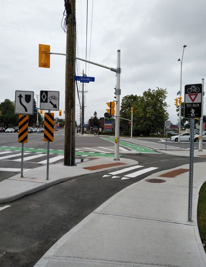
Curb extension (Ottawa, ON)
Right turn channel (Bend, OR)
Signalized intersection (Portland, OR)
18 | ALTA PLANNING + DESIGNElevation and Curb Profile
The elevation of a raised apron may be between the
existing road grade and the adjacent sidewalk or pedestrian
corner area. Many raised aprons use an intermediate height
between the two, allowing for a mountable surface while
still providing clear vertical distinction from the sidewalk.
For raised aprons, the profile of the edge of the mountable
element determines how easily a vehicle can mount it.
• A traversable curb is better for the stability of larger
design and control vehicles, but may not provide enough
deterrence for some managed passenger vehicles.
Traversable Curb (St. Louis Park, MN)
• A mountable curb typically has a steeper bevel,
providing more deterrence to passenger vehicles.
Atlanta, Salt Lake City, and Austin use curb profiles with a
vertical plus a mountable portion. Less frequent control
vehicles should be accommodated with greater vertical
portions, to increase the penalty for encroachment.
If pedestrians or bicyclists need to cross the apron,
traversable curbs may be more suitable.
Elevation and curb profile variations include:
Traversable Curb (Mississauga, ON)
Flush with roadway (Ottawa, ON) Mountable Curb (Salt Lake City, UT)
CORNER DESIGN FOR ALL USERS | 19Color and Materials
Color reinforces the distinction between the apron and
other road elements. A surface material that is the same
color as the sidewalk reinforces the distinction from the
roadway for drivers, but may encourage pedestrians to
dwell on it, as it may be mistaken as a continuation of the
pedestrian area. A more aesthetically enhanced apron
distinguishes it from both the roadway and sidewalk, but if
the surface finish looks too “nice” it may be unclear to truck
drivers that the surface is intended to be driven over.
Textured, colored concrete (Austin, TX)
The City of Austin found that a brick color worked best to
distinguish the mountable area from the roadway surface,
sidewalk and bikeway. Edge striping can also specifically
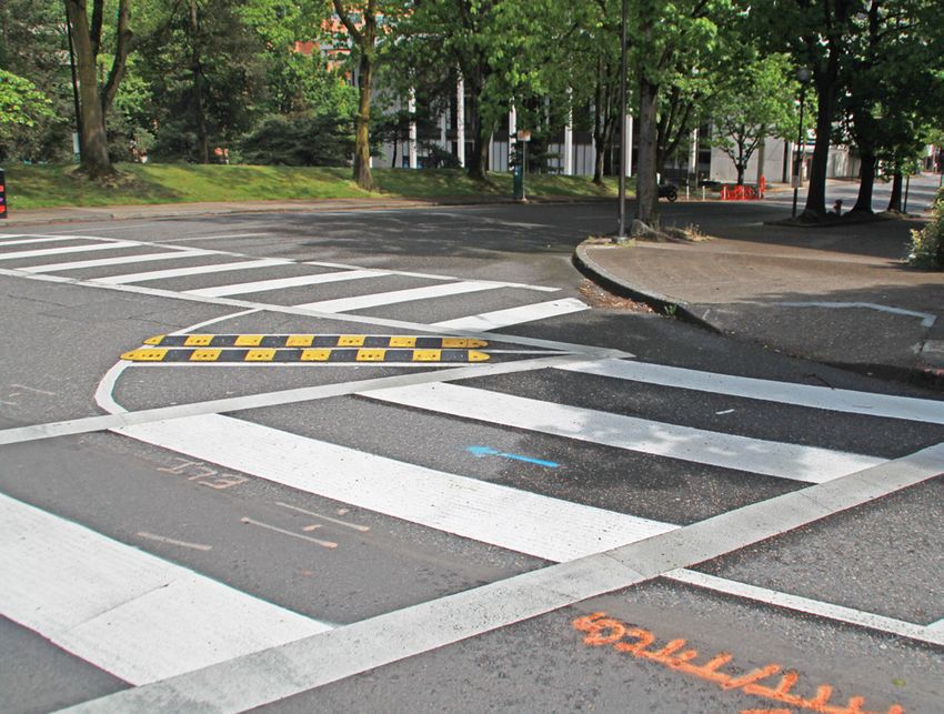
reinforce the desired turning path. The City of Portland uses
edge striping in applications where the turning path may
not be clearly conveyed by the apron shape, such as corner
speed humps (see Rumbles, Humps, and Bumps section
below).
Color and material variations include:
Pavers, cobbles or other similar materials (Atlanta, GA )
Pavers with concrete to denote walking path (Atlanta, GA)
Gore striping/hatching (Cambridge, MA)
Edge striping (Portland, OR)
20 | ALTA PLANNING + DESIGNRumbles, Humps and Bumps
Textured surfaces provide a tactile feedback to the
managed vehicle driver, making it intentionally unpleasant
to drive over the apron. Unlike aprons defined by curbs,
textured surfaces do not need to cleanly define a turning
path for the managed vehicle; while some cities, including
Portland, Oregon, use edge striping to reinforce the desired
turning path, New York City has experimented with a
box-shaped speed bump area. Experience from New York
City and Portland shows that modular speed bumps are an
effective retrofit application, requiring no reconstruction Speed humps/cushions (Portland, OR)
of the corners. At the time of publication, New York City
has implemented this treatment at over 300 intersection
corners. San José’s quick-build program took advantage
of readily-available pavement reflective markers to create
bumps in the apron area.
Cities like Ottawa, Ontario have experimented with rumble
strips within the apron, while other cities that do not need
to consider snow removal options have installed larger
bumps and humps in the apron. Textured or rumble strip
options may generate additional vehicle noise, which
should be considered in residential contexts. Speed bumps, defined turning path (Portland, OR)
Variations of rumbles and bumps include:
Speed bumps, square area (New York, NY)
Rumble strips/surface (Ottawa, ON)
Pavement reflective markers as bumps (San José, CA)
CORNER DESIGN FOR ALL USERS | 21Coverage/Extents
Aprons may pass through the crossing paths of pedestrians
and bicyclists or may terminate before and/or after.
Detectable warning surfaces should be placed outside of
the apron surface so as not to put pedestrians in risk of
conflict with a large turning vehicle. One exception to this is
Austin, Texas, which allows very infrequent control vehicles
(fire trucks) to mount over the area where pedestrians or
bicyclists would be expected to dwell. Similarly, stop bars
for bicyclists, where applicable, should be set back behind
aprons.
Variations in the coverage/extents of aprons include:
Tangent to physical corner, crosswalk painted over apron
(Portland, OR)
Between crosswalks (Portland, OR) Between crossrides (Ottawa, ON)
Crosswalk does not continue across mountable apron (Bend,
OR)
22 | ALTA PLANNING + DESIGNThis page intentionally blank
CORNER DESIGN FOR ALL USERS | 23Cambridge, MA 24 | ALTA PLANNING + DESIGN
03 POLICY SUPPORT
Implementing corner designs that reduce pedestrian exposure while still accommodating larger vehicles may constitute
a different approach to design for many transportation practitioners. Without a supportive policy framework and design
guidance, each project could meet a measure of resistance as the design is refined. Many agencies have adopted proactive
policies intended to aid designers when considering the needs of different roadway users.

The AASHTO Green Book (2018) identifies and addresses           The City of Edmonton, Alberta published its Complete
the need for design flexibility by stating that “the design     Streets Design Standards in 20185, which includes a section on
criteria presented in this policy are not fixed requirements,   corner radius (Section 3.6.2). The standard defines the design
but rather are guidelines that provide a starting point         vehicle based on the classifications of intersecting streets
for the exercise of design flexibility.”2 In response to the    and provides a “design domain” for corner radii to be used as
need for design flexibility, AASHTO further identifies three    a starting point. Guidance is provided for where design and
additional resources to aid engineers in applying flexibility   control vehicles may cross center lines of receiving roadways,
where appropriate. Policies can take many forms, but many       and where two-centered curves may be used. The standard
agencies are building more flexible design principles into      also provides a discussion on the use of mountable curbs
their local design standards, leaving no question as to their   in combination with truck aprons at intersection corners
applicability. The following examples are not intended to       to accommodate control vehicles (or less frequent design
be comprehensive, but to serve as inspiration for agencies      vehicles), and how to integrate them with pedestrian curb
looking to formalize policies and design standards that         ramps.
permit more flexible intersection design.
                                                                The City of Austin, Texas is updating its Transportation
Local Agency Examples                                           Criteria Manual in 2020 to define design and control vehicles,
                                                                turning path allowances, and encroachment criteria. The
The City of Toronto, Ontario created a new section in May       Criteria Manual contains the design criteria to support the
201818 to supplement its Road Engineering Design Guidelines     city’s code of ordinances. Austin has many constrained streets
focused on curb radii design. Some key highlights include       and one of the largest challenges has been to accommodate
defining what constitutes frequent truck turns, defining        the needs of the larger fire apparatus.
the design and control vehicles for a variety of intersection
contexts, and defining optimal turning vehicle speeds for       State/Provincial Examples
a variety of vehicle types (with a maximum of 10 mph or
                                                                The Georgia Department of Transportation covers large
15 kph). Large control vehicles are allowed to cross the
                                                                vehicle turns in its Design Policy Manual8 in Section 3.2. It
centerline and use the full width of the receiving roadway in
                                                                differentiates the design vehicle from the check (control)
some intersection contexts. Additionally, the City provides
                                                                vehicle which is more infrequent and may utilize “all available
the following supplementary resources:
                                                                space including opposing travel lanes and areas outside of
• A Curb Radii Design Worksheet is provided with the            travel lanes designed to accommodate off-tracking.” Local
  recommendation that it should be filled out and kept on       context is stressed when selecting design and check vehicles
  file for each project                                         with the use of simulation software recommended to model
                                                                the paths of both on projects.
• Truck and large truck right turning volumes at most
  major intersections, mitigating the need for field counts     The Florida Department of Transportation has established
  for projects                                                  guidance on accommodating design and control vehicles on
                                                                state roadways in the FDOT Design Manual, Section 201.66. It
• A series of design tables for a variety of corner
                                                                has similar definitions of design and control vehicles; however,
  configurations, varied by vehicle type, frequency, and
                                                                FDOT allows control vehicles to have minor encroachment
  lane widths, mitigating the need for AutoTURN analysis
                                                                onto curbs and areas within the curb return if no critical
  for conceptual design
                                                                infrastructure such as traffic signal poles are present.

                                                                                                    CORNER DESIGN FOR ALL USERS | 25
San José, CA 26 | ALTA PLANNING + DESIGN
04 RECOMMENDATIONS
This white paper has reviewed engineering design principles and behavioral characteristics of drivers and crossing
pedestrians as well as potential corner designs that can reduce the risk of a permissive turning collision between a vehicle
and a pedestrian or bicyclist. This section outlines a recommended intersection design strategy that can be adopted at any
level into an agency’s design process.

Identify Vehicles                                                Managed vehicles, being the most commonly present
                                                                 vehicle, should be provided a carefully selected effective
Alta recommends identifying the relevant types of                turn radius that self-enforces the desired design speed. For
vehicles that will be using each intersection, which will        this to work, the corner must not only take into account
vary depending on roadway classification and context.            the physical radius, but should utilize the “fastest path”
For example, a local street intersection with an arterial        methodology commonly used in roundabout design
roadway will have different control vehicles than an arterial    to validate the design speed. Despite a smaller radius,
intersection with a collector. Similarly, intersections with     extenuating factors discussed in the section on “physical vs.
frequent turning buses will have different considerations        effective radius” may still allow faster turning than desired,
than those with no bus service. Projects should be validated     and adjustments to the physical radius may be necessary.
to their local conditions. Emergency vehicle access must         The mountable apron should discourage use by the
also be considered (see Section 03 for further discussion).      managed vehicles.
Furthermore, Alta recommends agencies adopt the NACTO
definitions of the Managed, Design, and Control vehicles.        Select Materials
This framework is extremely useful when selecting which
vehicles need to be considered and how they will travel          The corner typologies and case study examples in this
through the corner.                                              white paper show a variety of possible designs in use
                                                                 throughout North America. No two cities, at the time of
Define Turning Paths                                             writing, are alike. Agencies seeking to adopt mountable
                                                                 corner designs should carefully consider materials, drainage
This white paper recommends that each intersection               standards and implications, use of accent colors, and
under design be specifically tailored to the design vehicles     use of raised mountable curb profiles to best serve their
expected to use it. The important distinction here is to         communities. Standardization should be a local goal, so
not utilize standard details or to simply consult vehicle        that new intersections or retrofits use similar materials and
turning profile data sheets. Rather, turning software such as    treatments to promote uniformity and driver expectancy on
AutoTURN should be utilized at each intersection to provide      the local level.
certainty that allocated space is not only appropriate to
accommodate vehicle turning needs, but also minimizes            Monitor Results
pedestrian crossing distance and risk. Some larger control
vehicles can be modeled at slower 10 mph (15 kph) or crawl       Roadway safety is a topic that is supported across the
speeds to optimize the design.                                   population. Monitoring programs that can quantify the
                                                                 safety benefits will be helpful in allocating funding to
Control vehicles should be accommodated utilizing all            improve existing intersection corners. If all cities could show
receiving lanes and in some lower-order streets be allowed       results similar to San Francisco’s 100% observed driver
to cross the centerline if extremely rare in frequency.          yielding to pedestrians, it would be logical that safety funds
                                                                 would be easily prioritized for corner improvements on a
Design vehicles should be allowed to complete their turn
                                                                 large scale.
by utilizing a mountable apron with waiting pedestrians and
bicyclists held outside of this swept path.

                                                                                                      CORNER DESIGN FOR ALL USERS | 27
New York City 28 | ALTA PLANNING + DESIGN
05 CASE STUDIES
To support this white paper, the authors conducted interviews with staff at nine US and Canadian agencies
who have implemented some form of truck apron in their corner designs. Each agency has developed
locally context-sensitive solutions which differ from each other. Interviews focused on the particular
problem being solved, the solution, the efficacy of the designs, and any key takeaways or lessons learned
through experience. It is Alta’s hope that the information contained within these case studies will help
normalize these design principles in everyday intersection design throughout the US and Canada.

             PORTLAND, OR

                                                                      MISSISSAUGA, ON
                                                ST. LOUIS PARK, MN
               BEND, OR

                                                                         NEW YORK CITY, NY

             SAN JOSÉ, CA

                                                                      ATLANTA, GA

                                              AUSTIN, TX

Agencies Consulted
City of Mississauga, Ontario, Canada

City of Austin, Texas, USA

New York City Department of Transportation, New York, New York, USA

Upper Westside Improvement District, Atlanta, GA, USA

Atlanta Downtown, Atlanta, Georgia, USA

Portland Bureau of Transportation, Portland, Oregon, USA

City of San Jose, San Jose, California, USA

Oregon Department of Transportation, Region 4, Oregon, USA

Minnesota Department of Transportation, Minnesota, USA

                                                                                             CORNER DESIGN FOR ALL USERS | 29
CASE STUDY
MISSISSAUGA, ONTARIO, CANADA
The design solution is an intermediate-height apron with
KEY TAKEAWAYS a salmon-colored concrete surface separated from the
A traversable curb profile to define the apron appears roadway by a traversable curb. The design vehicle is a
to work well at deterring passenger vehicles, even with WB-20 truck (similar to a WB-67 in the United States); as
a temporary asphalt surface. This may be due to the this is the only vehicle type expected to use the apron.
large apron radius not imposing significant restrictions The apron maintains the previous corner radius, while the
on smaller turning vehicles. physical corner radius was adjusted to a two-centered
curve to suit the observed truck turning path, and was
verified with AutoTURN. When complete, the painted
crosswalk and crossride will extend only across the asphalt
EGLINTON AVENUE WEST AT
portion of the roadway, and the apron will be left without
MISSISSAUGA ROAD
pavement markings.
Context
Efficacy
Eglinton Avenue West is a major truck route, and
At the time of this writing, the construction was not
Mississauga Road provides the main goods movement
complete, however the apron path had been implemented
connection into the nearby village of Streetsville in
with a temporary asphalt surface. The City has visited
Mississauga. Mississauga Road has one receiving lane, so
the temporary condition multiple times and noted that
there is little opportunity for trucks to oversteer through the
observed compliance is excellent; all passenger vehicles
turns when making the westbound right turn movement. As
are avoiding the apron, while trucks are using it without
a result, the back wheels of trucks frequently sweep across
encroaching onto the sidewalk. When the project is
the pedestrian area and the adjacent boulevard. In 2020,
completed in Summer 2020, including the trail and
the City of Mississauga added a shared use path along the
crossride, the City plans to conduct more substantial field
north side Eglinton Avenue, which triggered an opportunity
observations.
for design improvements at the intersection.
Problem Solved Typology
Turn type Signalized intersection
The problem was two-fold: the City wanted to provide a
Accommodation Type Dual path
legitimate turning path for trucks at this intersection, but
Elevation and Curb Profile Traversable (3 inches / 75 mm)
with the planned trail project, they were concerned that
Color and Material Red painted concrete
increasing the physical corner radius would lead to faster
Rumbles and Bumps None
vehicle turning speeds, worsening the comfort level for
Coverage/Extents Fully through corner
bicyclists and pedestrians.
Solution and Process
A truck apron was proposed as a solution to the problem.
The City conducted a peer review and spoke with other
agencies, then circulated an internal memo with its
proposed design approach. One of the greatest concerns
raised through the design development was the potential
for pedestrians to stand on the apron surface.
30 | ALTA PLANNING + DESIGNABOVE: As of Summer 2020, the
corner design is partially complete.
The final design will feature a
painted red concrete apron surface
and a crossride. Credit: City of
Mississauga
AT LEFT: Design drawings for the
intersection showing the multi-use
trail (M.U.T.) that will be added.
Credit: City of Mississauga
CORNER DESIGN FOR ALL USERS | 31CASE STUDY
ST. LOUIS PARK, MINNESOTA
a tighter path. The apron meets the roadway with a fully-
KEY TAKEAWAYS mountable curb profile, and is separated from the sidewalk
Freeway interchanges are especially likely to require area by a vertical barrier curb. Flush dropped curbs with
accommodation of large vehicles. When higher tactile surface indicators meet the apron surface at the
pedestrian and cycling volumes are expected, aprons pedestrian crossings.
can be effective for accommodating all users. Crosswalk markings are provided, but they only extend
across the asphalt surface and terminate at the apron
edges. Solid white painted lines define the edge of the
WOODDALE AVE S AT MINNESOTA apron for added visibility.
HIGHWAY 7 INTERCHANGE
The control vehicle for the aprons is a WB-65 truck, which
was dictated by MnDOT given the context as a freeway
Context
interchange. In each of the three corners, the corner angle is
Minneapolis is currently expanding its LRT network to skewed and only one receiving lane is available, requiring a
the southwest, into the municipality of St. Louis Park and large physical corner radius. The apron radii are significantly
beyond. To improve connectivity to the future LRT station, smaller, leading to large apron areas. The asphalt area of
a local high school, and support future development, the right turn channel throats is kept to roughly 12 feet or
St. Louis Park commissioned the reconstruction of the 4 meters for the managed vehicle.
Wooddale and MN Highway 7 freeway interchange,
including the widening of the overpass structure by 12 feet Efficacy
on each side.
Though a detailed assessment has not been conducted,
anecdotally, based on post-construction site visits, the
Problem Solved
designs appear to be working as intended.
To support walking and cycling comfort in the area,
one goal of the project was to minimize the pavement Typology
areas of each of the crossings. At the same time, MnDOT
Right turn Type Stop-controlled intersection corner (1),
required that the intersection corners support the turning
yield-controlled right turn channel (2)
movements of WB-65 trucks.
Accommodation Type Dual path
Elevation and Curb Profile Traversable (3 inches / 75 mm )
Solution and Process
Color and Material Concrete, white painted stripe to
delineate apron
The reconstructed intersection contains three corners with
Rumbles and Bumps None
truck aprons – one regular corner and two yield-controlled
Coverage/Extents Fully through corner
right turn channels. Inspired by the effectiveness of truck
aprons in roundabouts, the lead consultant for the project
proposed the truck apron design approach for the three
right turn treatments, and it was approved by St. Louis Park
as well as MnDOT.
The chosen design treatment consists of a concrete apron
surface at intermediate height, providing an area for the
swept path of trucks while restricting passenger vehicles to
32 | ALTA PLANNING + DESIGNABOVE: A road user’s view of one of the right turn channels at the interchange with a traversable apron treatment.
BELOW: A close-up view of the same channel showing the traversable curb profile.
CORNER DESIGN FOR ALL USERS | 33CASE STUDY
NEW YORK CITY, NEW YORK
Passenger vehicles are used as the managed vehicle for
KEY TAKEAWAYS the corner bump areas, and AutoTURN is typically used to
validate the turning path. Trucks and buses are expected to
1. Focus on being as data driven as possible, don’t do it
turn by driving over the mountable areas.
on a request basis.
The corner mountable areas are typically placed between
2. Forget the bollards and go right to the rubber speed the two crosswalks and are outlined with yellow pavement
bumps. markings when configured for left turns and white pavement
markings when configured for right turns. Black and yellow
speed bumps are either placed diagonally within the defined
CITY-WIDE PROGRAM area or along the edges.
For winter maintenance, the speed bumps are typically
Context
placed outside of the snowplow sweep path, and after one
As part of NYC DOT Vision Zero program, the agency wanted winter season with a few days of plowing operations, there
to target the high number of collisions due to motorists was minimal damage to the implemented treatments.
cutting corners when turning left from a one-way street onto
The implementation of these interventions is tied exclusively
another one-way street. The City’s program also includes
to pedestrian injury data, with high-injury locations being
“Centerline Hardening,” where left turns are from a one-way
prioritized. The program deliberately does not operate on
to a two-way street. In New York City, left-turn-related killed
a public request basis to ensure that the most sensitive
or seriously injured (KSI) crashes outnumber right-turn locations are targeted first.
crashes by 3:1 (19% vs 6%). Certain high-injury right-turn
pedestrian crash areas have also been treated, though these Efficacy
are much fewer in number.
Over 300 locations have been treated as of early 2020. NYC
DOT has conducted studies of the effectiveness of these
Problem Solved
measures and found turning speeds are reduced by up to
NYC DOT’s data revealed that left turns pose a greater threat 40% with the corner wedges, and serious pedestrian injuries
to pedestrian safety than right turns. This is particularly are down 30% to 40%.
due to the nature of many streets being one-way and that
the driver side vehicle pillar limits visibility of pedestrians The agency also reports data on the maintenance of the
for drivers turning left. The goal was to develop a scalable rubber speed bumps. In an 18-month study period, 55 of 95
design solution to slow down turning vehicles and force locations studied required no repair or replacement, and on
turns at closer to a right angle to reduce the probability and average there were 1.15 repair/replacements per location.
severity of collisions between motor vehicles and vulnerable
road users.
Typology
Turn Type Left turns from a one-way street to
Solution and Process another one-way street. Some right turns.
Mostly at signalized intersections.
Initially NYCDOT experimented with the creation of “corner
Accommodation Type Dual path
wedges” using flex post bollards, but these were frequently
Elevation and Curb Profile Flush with roadway
damaged and became a significant maintenance issue. In
Color and Material Yellow pavement markings to define
recent years the agency has moved to a mountable bolt-in
turning path and accent the rubber speed
rubber bump solution, placed on the corner between the
bumps
two roadways.
Rumbles and Bumps Rubber speed bumps
While many NYCDOT implementations have drawn resistance Coverage/Extents Between crosswalks
and opposition, their corner wedges program has been
implemented with relative ease and broad acceptance.
34 | ALTA PLANNING + DESIGNABOVE LEFT: a passenger vehicle turns left at the intersection of two one-way streets, steering around a rounded corner apron with diagonal
speed humps. Credit: NYC DOT. ABOVE RIGHT: an example of a square corner apron outlined with speed bumps. Credit: NYC DOT.
BELOW: a left-turn speed bump design combined with a hardened receiving centerline treatment. Credit: NYC DOT
CORNER DESIGN FOR ALL USERS | 35CASE STUDY
AUSTIN, TEXAS
KEY TAKEAWAYS
1. Work collaboratively with city fire departments
2. Use high-contrast materials to increase visibility of
the mountable area and deter passenger vehicles
CITY-WIDE PROGRAM
Context
This Dual Path apron at a channelized turn lane helps slow vehicles
The City of Austin is working to design and implement through the turn. Credit: City of Austin
pedestrian safety improvements and separated bikeways
in many constrained environments. Many of the city’s
streets are constrained in width, making improvements for that the vehicle can overhang constrained locations
bicycling and walking difficult when accommodating larger without coming into conflict with street furniture and signal
vehicle turns. The city desires solutions which do not allow equipment during design. These mountable curbs are not
any encroachment from passenger vehicles. seen as appropriate for more frequent large vehicles like
buses.
Problem Solved
Working with the fire department, Austin Transportation
Austin has developed a mountable curb for bikeways that Engineering staff have developed a mountable curb profile
still accommodates mounting by fire apparatus, but would which seeks to make the curb undesirable for passenger
not be inviting for passenger vehicles. It is also expanding vehicles, while allowing fire apparatus to access and mount
use of mountable dual path corners for more frequent if needed.
vehicles. Each project is treated as a custom design.
The city has a three-tiered design review process for new
projects which features:
Solution and Process
1. Internal Transportation Engineering staff geometric
Given the infrequent passage of fire trucks, it was
review. Designers know which elements have support
determined that these vehicles may encroach on the areas
in various approval positions and have these people on
of an intersection where pedestrians or bicyclists may
the review team. Design assumptions are defined prior to
queue. Physical corner radii are set based on the design
design. This includes running simulations on:
vehicle, and mountable corner elements are provided to
a. Passenger vehicle turning at 10 mph (15 kph)
allow fire trucks to make turns. Large vehicles are permitted
b. Design vehicles
to encroach into the adjacent approach lane by straddling
c. Control vehicle (Quint)
the lane line and can complete their turn through mounting
hardscape if needed. Austin has a design process which 2. Fire Marshal’s office review. The office has an engineering
analyzes the turn path of the largest fire apparatus (the review team which does street design review.
“Quint”) with additional modeled extents including the
bucket envelope, body envelope, the front and rear tire 3. Field engineering review during construction to make any
paths and the overall apparatus path. Doing so ensures adjustments due to site realities.
36 | ALTA PLANNING + DESIGNYou can also read