MPO Guide for Implementing DSRC Technology in PennDOT District 8-0
←
→
Page content transcription
If your browser does not render page correctly, please read the page content below
MPO Guide for
 Implementing DSRC
      Technology in
PennDOT District 8-0   June 2019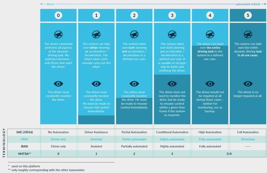
This document is intended to assist PennDOT District 8’s Planning Partners and MPOs/RPOs across
Pennsylvania with their development and implementation of Dedicated Short-Range Communication
(DSRC) technology into the planning process. DSRC technology provides the opportunity to create a safer,
more efficient, roadway network. This document is comprised of three sections which are as follows:

   1. Define the Technology – This section summarizes what is meant by Connected and Automated
      Vehicles (CAV) including the differences between these terms and various roles of communication
      technology for Connected Vehicles (CVs). Some of the pros and cons of the leading technology
      candidates, such as DSRC, Cellular Vehicle to Any Device (C-V2X) and 5G, are explained within the
      document.
   2. DSRC V2I Deployment Impacts and Priorities – This section summarizes possible CV applications
      using DSRC, the likely/expected penetration timeline, and a GIS-based criteria map to assist in the
      selection of corridors which are best suited for DSRC technology. There are several
      communications technologies that could advance vehicle-to-infrastructure (V2I) applications,
      such as DSRC, C-V2X, and Cellular 5G. However, this plan is focused on DSRC as it has been widely
      tested and deployed in the U.S.
   3. Cost & Design Considerations – This section provides general, preliminary, cost and design
      considerations along with scenario schedule recommendations to assist with understanding when
      facilities should undergo design and construction. Additional topics such as compatible
      equipment identification, and ownership and maintenance responsibilities, are also addressed.

                                                 Page i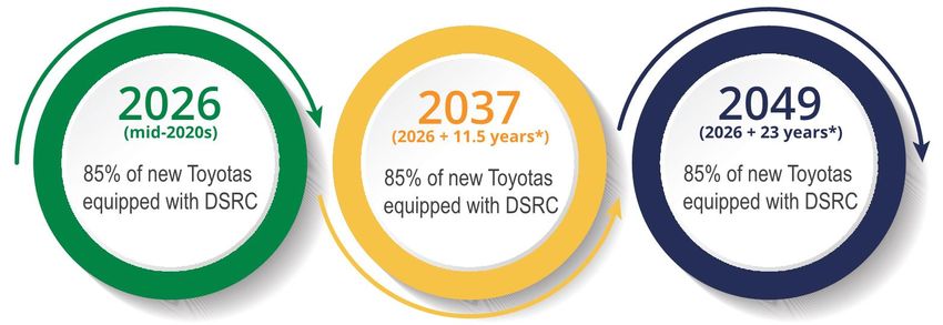
ADAS          Advanced Drive-Assisted Systems
ATC           Advanced Traffic Controller
AV            Automated Vehicle
BSM           Basic Safety Message
CAV           Connected and Automated Vehicle
Cellular 5G   Cellular 5th Generation
CMAQ          Congestion Mitigation and Air Quality Improvement Program
CV            Connected Vehicle
C-V2X         Cellular Vehicle-to-Everything
DSRC          Dedicated Short-Range Communications
FCC           Federal Communications Commission
FMVSS         Federal Motor Vehicle Safety Standard
GIS           Geographic Information System
IPv6          Internet Protocol Version 6
I-SIG         Intelligent Traffic Signal System
ITS           Intelligent Transportation System
ITS-JPO       USDOT’s Intelligent Transportation System Joint Program Office
LRTP          Long-Range Transportation Plan
MMITSS        Multi-Modal Intelligent Traffic Signal System
MPO           Metropolitan Planning Organization
NTCIP         National Transportation Communications for Intelligent Transportation Systems Protocol
OBU           On-board Unit
PCIT          Pennsylvania Crash Information Tool
PoE           Power-over-Ethernet
RPO           Rural Planning Organization
RSU           Roadside Unit
SAE           Society of Automotive Engineers
SPaT          Signal Phasing and Timing
STIP          PennDOT State Transportation Improvement Program
TIM           Traveler Information Message
TIP           Transportation Improvement Program
TSAMS         Traffic Signal Asset Management System
TSMO          Transportation Systems Management & Operations
TYP           Twelve Year Program
V2I           Vehicle-to-Infrastructure
V2V           Vehicle-to-Vehicle
V2X           Vehicle-to-Everything
WAVE          Wireless Access in Vehicular Environment protocol

                                               Page ii
Document Overview .............................................................................................................................. i
      Common Terms and Acronyms ............................................................................................................. ii
Section 1. Defining the Technology ....................................................................................................1
   1.1.      Technology Background ................................................................................................................ 1
      Automated Vehicles .............................................................................................................................. 1
      Connected Vehicles ............................................................................................................................... 2
      Connected and Automated Vehicles (CAV) .......................................................................................... 5
   1.2.      Role of Communication Technologies for Connected Vehicles – DSRC & 5G............................... 5
      DSRC ...................................................................................................................................................... 5
      Fifth Generation (5G) Cellular Communications ................................................................................... 7
Section 2. V2I Deployment Impacts & Priorities .................................................................................9
   2.1.      Priority Applications ...................................................................................................................... 9
      Safety .................................................................................................................................................... 9
      Mobility ............................................................................................................................................... 10
      Environment........................................................................................................................................ 11
      Agency Data ........................................................................................................................................ 11
   2.2.      Projected Penetration Rate Scenarios & Anticipated Impacts ................................................... 12
      General Timeline ................................................................................................................................. 12
      Scenarios ............................................................................................................................................. 13
      Planning for Connected Vehicles ........................................................................................................ 15
   2.3.      Corridor Prioritization ................................................................................................................. 16
      Initial Criteria....................................................................................................................................... 16
      Urban Corridor Criteria ....................................................................................................................... 16
      Rural Corridor Criteria ......................................................................................................................... 17
      Feasibility of Implementation ............................................................................................................. 17
   2.4.      Long Range Plan Integration ....................................................................................................... 18
      Priority Corridor Identification ............................................................................................................ 18
      Stakeholder Engagement .................................................................................................................... 18
      Plan Integration................................................................................................................................... 19

                                                                           Page iii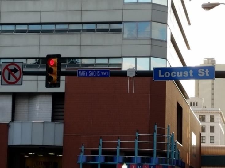
Future of DSRC Coordination Plans..................................................................................................... 19
Section 3. Cost & Design Considerations .......................................................................................... 20
   3.1.      Project Selection ......................................................................................................................... 20
      Selecting the Right Project .................................................................................................................. 20
      Project Lifecycle Timing ...................................................................................................................... 20
      Project Types ....................................................................................................................................... 21
      Project Funding ................................................................................................................................... 21
   3.2.      Design Considerations................................................................................................................. 22
      Compatible Infrastructure .................................................................................................................. 22
      Unit Placement.................................................................................................................................... 22
   3.3.      Cost Overview ............................................................................................................................. 24
      Element Cost Breakdown for the Deployment of One DSRC Unit ...................................................... 25
      Deployment Cost Scalability ............................................................................................................... 26
      Additional Cost Considerations ........................................................................................................... 26
   3.4.      Ownership and Maintenance Responsibilities............................................................................ 27
Appendix A – Current Pilot Programs ................................................................................................ 29
Appendix B – Example 2019 TIP Projects in PennDOT District 8 ......................................................... 30
References....................................................................................................................................... 31
      Section 1. Defining the Technology .................................................................................................... 31
      Section 2. V2I Deployment Impacts and Priorities ............................................................................. 32
      Section 3. Cost & Design Considerations ............................................................................................ 33

                                                                        Page iv
Emerging transportation technologies are promising to significantly improve the safety and accessibility
of our nation’s transportation network. Technologies such as those enabling Connected and Automated
Vehicles propose to reduce crashes, improve transportation efficiency, and increase transportation access
to those with mobility challenges. While connected and automated vehicles promise to be the future of
transportation technology, both of these solutions rely on different types of technology and could require
different types of interaction with the transportation infrastructure and support environment. These
technology types could work independently, or ultimately in cooperation, with each other.

Automated vehicles (AVs) by definition supplement or replace, part or all of the dynamic driving task of a
human vehicle operator. Within the 5 levels of automation adopted by the Society of Automotive
Engineers (SAE) and the U.S. Department of Transportation (USDOT), the “highly automated vehicles”
exhibit level of automation 3 or higher. These levels (from 0 to 5) are described in Figure 1. The advanced
automated driving systems for these future vehicles are designed and built by vehicle manufacturers,
frequently partnering with technology companies.

Currently, the highest level of automation available for a consumer passenger vehicle is Level 2, most
commonly seen in vehicles manufactured by Tesla, and the SuperCruise function in some General Motors
products. Other automobile manufacturers will also soon be bringing Level 2 vehicles to market. Most
currently available vehicles with automation Level 2 do not require any specific input or information from
the infrastructure or transportation system operators. However, as an example, SuperCruise works only
where General Motors has previously mapped the area. The vehicle itself has data about the road
network, and this data could become stale and inaccurate. Low-speed transit vehicles that can operate at
an automation Level 4 are available, but currently are restricted by federal regulations to operate at no
higher than 25 mph on public roadways. These systems also have limited ability to operate in a dynamic,
uncontrolled traffic environment.

                                               Page 1 of 33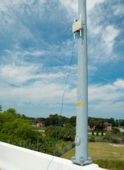
Figure 1 – Displays the various levels of Autonomy. Level 0 represents traditional driving and level 5 represents
complete vehicular autonomy.

Auto manufacturers are working on deploying passenger vehicles with Level 4 automation capabilities
within the next 5 years, that can reportedly be deployed in a very controlled, geo-fenced, and centrally
operated system.

Connected Vehicle technologies, in which vehicles can exchange real-time information with other vehicles
and/or transportation infrastructure systems, are designed to support a human driver in performing the
dynamic driving task. With a Connected Vehicle, the human driver is still responsible for all aspects of the
dynamic driving task but may be supplemented by existing advanced driver-assistance systems (ADAS)
such as cruise control, parking assistance, blind spot detection, automated emergency braking and lane
departure warnings. Connected Vehicle technology does not take control over the vehicle systems; it
provides real-time information to assist the driver in avoiding imminent safety hazards or could provide
real-time information back to transportation infrastructure owners and operators. For example,
transportation entities could be provided with traffic data to facilitate where improvements need to be
prioritized.

                                                 Page 2 of 33
In addition, Connected Vehicles are expected to decrease traffic law violations and can be tied into
emergency services for faster deployment. Roadway crews can also be notified of roadway safety hazards
at specific locations because of higher resolution monitoring and sensor data collection made possible
with Roadside Unit (RSU) installation.
Automated data collection from implementing Connected Vehicle technology on infrastructure can be
useful to assess the effectiveness of the roadway by documenting vehicle speed, acceleration, delay,
queue, travel time and traffic density. Origin – destination studies can also provide more insight on what
kinds of drivers are on the road, and when and where they are driving.
Connected Vehicle systems and applications generally fall under the following types of operation:
Vehicle-to-Vehicle (V2V) – Vehicles exchange data with each other regarding their respective status,
speed, direction, and other characteristics, allowing them to generate warnings to avoid collisions. V2V
applications require a vehicle to be equipped with compatible On-Board Units (OBUs), which broadcast,
receive, and process the data from other similarly equipped vehicles. Some benefits of V2V connectivity
are provided in Figure 2.
Vehicle-to-Infrastructure (V2I) – Vehicles exchange data with roadside infrastructure, such as traffic
signals, allowing for a variety of safety and mobility applications, such as (but not limited to) generating
warnings within vehicles of a pending red light, or generating speed warnings to vehicles prior to traveling
around a curve. In a V2I network, communications occur between a vehicle equipped with an OBU, and
infrastructure equipped with one or more RSUs. The RSU’s broadcast data to a vehicle equipped with an
OBU, which in turn receives and processes the data, generating any pertinent warning, alert, or
information for the driver. RSU’s may also be configured to receive broadcasts from vehicle OBU’s,
allowing the exchange of real-time and near real-time data with a larger communications network,
allowing for dynamic analysis of the performance of the transportation network. Some additional benefits
of V2I connectivity are provided in Figure 2.
Vehicle-to-“Everything” (V2X) – A more encompassing term for connected vehicle applications, where
vehicles exchange data with other vehicles, the infrastructure, pedestrians, or a network environment.
The key to any connected vehicle system are the applications that the exchanged data allows. USDOT, in
conjunction with public sector transportation agencies and vehicle manufacturers, has identified dozens
of potential connected vehicle applications that can be deployed.
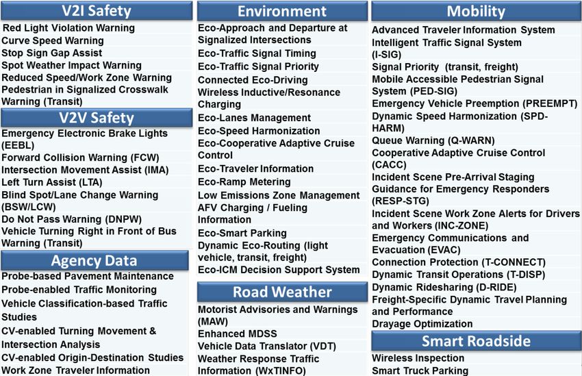
Additional CV benefits related to Agency Data, the Environment, Road Weather, Mobility, and Smart
Roadside are also provided in Figure 2. Information regarding specific examples in Figure 2 can be found
at the USDOT’s Intelligent Transportation System Joint Program Office (ITS-JPO) Website.
Page 3 of 33Figure 2 – Lists many of the capabilities of Connected Vehicle technology. Source: USDOT
Currently, only a few models of vehicles come equipped with connected vehicle capabilities. However,
announcements by major automobile manufacturers such as General Motors and Toyota promise an
increase in the number of new vehicles that will be equipped with these technologies. In addition, there
are “after-market” devices that can be added to existing vehicles that enable the use of connected vehicle
communications and applications.
There are currently functional vehicle-to-infrastructure (V2I) deployments in at least 19 states. In
Pennsylvania, Harrisburg has 8 operational RSUs, Pittsburgh has 46 operational RSUs and an additional 45
planned for deployment, and Philadelphia is planning to equip 160 RSUs by 2020. Most of these are limited
pilot-type deployments to demonstrate the feasibility of the technology and applications, although there
are a few deployments that are intended to be longer-term and expandable.
Early connected vehicle deployments have been spearheaded by US DOT’s Intelligent Transportation
System Joint Program Office (ITS-JPO), which has distributed grants for developing and implementing the
technology as well as provided documentation and technical resources to agencies executing ITS projects.
The Federal Highway Administration (FHWA) has also developed guides in ITS architecture
implementation from a system engineering standpoint to plan, design, construct, test and operate CV
systems. In addition, a national connected vehicle Signal Phasing and Timing (SPaT) deployment challenge
is challenging state and local public sector transportation infrastructure owners and operators to deploy
DSRC infrastructure with SPaT broadcasts in at least one corridor or network in each of the 50 states by
January 2020. Progress and resources can be found at www.transportationops.org/spatchallenge.
Page 4 of 33In the coming years, a vehicle may be connected; or, it may be automated. In reality, the most benefit
will be achieved when these two solutions are deployed concurrently, resulting in Connected and
Automated Vehicles. While the future of CAVs are both promising and exciting, there are currently over
350 million registered vehicles on the nation’s roadways. Thus, for the foreseeable future one can
expect a “mixed fleet,” including: a mix of non-automated vehicles, vehicles with varying levels of
automation, and connected vehicles.
Connected vehicles operating in a V2I and / or a V2V environment require secure, high-speed, low-latency
(low delay) communications. Many connected vehicle applications are safety-related and require a
reliable communications system. Currently, there are two types of communication technologies that are
being promoted for connected vehicle systems: DSRC, and 5G. While some of the hardware configurations
may be different between these technologies, the intent of the systems is the same; using a defined
wireless spectrum to quickly and securely transmit critical safety and mobility information.
Dedicated Short-Range Communications (DSRC) is a wireless communication technology, much like the
Wi-Fi communications that many are familiar with, that allows vehicles to communicate with other
vehicles and the surrounding infrastructure via short range signals. The short range signals avoid/minimize
signal overlap and allow the vehicle to have a 360-degree communication with similarly-equipped
infrastructure and vehicle systems.
The term “Dedicated” refers to the fact that the Federal Communications Commission (FCC) has set aside
a communications bandwidth specifically for transportation safety purposes. DSRC uses channels that
transfer information through a combination of OBUs and RSUs facilitating V2X communications through
the licensed 5.9 GHz band (5.850-5.925 GHz band). This bandwidth was allocated to ITS operations by the
FCC for uses in “traffic light control, traffic monitoring, travelers' alerts, automatic toll collection, traffic
congestion detection, emergency vehicle signal preemption of traffic lights, and electronic inspection of
moving trucks through data transmissions with roadside inspection facilities” (FCC, 1999).
In terms of hardware or physical installation, RSUs operate with point-to-point connections to deliver
deployment location-specific messages. For example, an intersection may need an RSU that is
programmed with a signalized intersection’s road geometry to advise an optimal driving speed for
approaching vehicles 150 feet before getting to the queue. However, a bridge historically known to have
ice patches in the winter, may have an RSU to communicate a weather warning when appropriate climate
changes occur. RSUs will likely be mounted overhead to achieve a better line-of-sight for the radio
communications. They will also require a transmission method, typically Power-over-Ethernet (PoE),
Page 5 of 33which pairs data transmission and power. PoE pairs data and power, but only for short distances (100m
max). For areas requiring additional coverage a PoE injector can be used as a repeater to transmit the
signal over longer distances.
Standards referenced by USDOT include IEEE 802.11p and the 1609 Wireless Access in Vehicular
Environment (WAVE) protocol. ITS hardware and infrastructure have been developed for these systems,
but the technology will continue to further mature as additional deployments occur. This technology will
consist of “open air” broadcasting, meaning anyone (including public transportation agencies) with
compatible equipment can freely access any broadcast data. However, no personally identifiable
information is involved with DSRC systems “open air” broadcasting. Any fixed site that is broadcasting
over the 5.9 GHz band is required to be licensed by the FCC.
Additional standards have been developed by the SAE for V2X communications involving Basic Safety
Messages (BSMs) generated by OBUs, and Traveler Information Messages (TIMs) and SPaTs which are
generated by RSUs. Collection of traffic messages and statistics from DSRCs can be tied into a backhaul
network (a center for data reception, collection and distribution) for remote management and data
processing.
DSRC Pros
DSRC is a guaranteed technology that has been proven for more than 12 years, with significant guidance
and resources available to deploy it nationwide. DSRC-based connected vehicle systems have already
been implemented with preliminary regulatory measures, mainly regarding cybersecurity and standards
for ITS and other V2I infrastructure installation. Transportation agencies across the country, working
jointly with vehicle manufacturers and technology companies, have deployed and support DSRC-based
systems.
One of the greatest advantages of DSRC is its ability to operate without network connectivity. DSRC
communications can still be implemented in rural areas with little to no backhaul (fiber optic or cellular)
coverage in V2V and V2I applications. This allows for many, especially safety-based, V2I applications to be
operated locally in rural areas.
DSRC Cons
DSRC-based V2I systems require the deployment of RSUs within roadway right-of-way. Long-term
updates and maintenance would fall to the transportation infrastructure owners and operators. Currently,
there is limited technical experience when it comes to configuration and maintenance of RSUs, which may
hinder municipal deployment of the technology, especially at the local government level.
Agencies may be discouraged from supporting DSRC deployment under the assumption that rapid
development of technology, standards, software, and methods may render their initial investments
obsolete. However, this can be offset by supporting efforts to make much of the initial hardware
investments in DSRC systems compatible with future emerging technologies that may exist in the V2X
world.
Page 6 of 33While the financial burden of DSRC systems is expected to fall largely to the public sector, ubiquitous
deployment of roadside infrastructure is not required to achieve major benefits. Localized deployment
of infrastructure can achieve safety and mobility goals; additionally, V2V applications do not require
supporting roadside infrastructure.
DSRC Implementation Requirements
Standards for a DSRC-based deployment, while still ongoing some development, have matured
significantly as deployments have progressed. Some of the following standards are available for DSRC
deployments:
• SAE J2735 and SAE J2945 standardize the transmission of data in a DSRC environment.
• National Transportation Communications for Intelligent Transportation System Protocol (NTCIP)
establishes compatibility requirements with roadside communication infrastructure.
• IEEE 802.11p and IEEE 1609 standardize the technical requirements of DSRC communications.
• The USDOT has developed a specification for DSRC RSUs (Version 4.1).
• The FCC has provided guidelines for licensing devices within the 5.9 GHz communications bandwidth
for DSRC and ITS applications.
The National Highway Traffic Safety Administration (NHTSA) has issued a notice of proposed rulemaking,
proposing Federal Motor Vehicle Safety Standard (FMVSS) No. 150 Vehicle-to-Vehicle Communication
Systems, which require all light vehicles to have V2V communications using OBUs with DSRC capabilities.
The proposed rulemaking and comments from interested parties is currently in front of the United States
Office of Administrative Services (OAS) for future action.
Cellular technology is working to advance to 5G connectivity for higher bandwidth, accessibility and
network density. 5G is a radio access technology that will be implemented by retrofitting existing
platforms such as 2G, 3G, 4G, and Wi-Fi. Because 5G it is not yet suitable as the single cellular platform to
support the different needs of today’s users, it will need to coexist with existing platforms until fully
implemented. By the installation of many small cell towers, a shorter range is obtained which allows for a
higher bandwidth and faster speeds. Due to the installation requirements, 5G services will be rolled out
to densely populated areas initially and will take many years to expand to rural, or less dense, areas.
It would be possible to leverage the standards developed by a 5G cellular network to develop 5G-based
V2X technologies. With a 5G-based V2X system, operations would be very similar to a DSRC-based system,
in that dedicated equipment would be required to generate and receive data between vehicles and the
infrastructure. 5G V2X systems would use the same 5.9 GHz band for communications between vehicles
and infrastructure as DSRC systems; the differences lie in the equipment and backhaul communication
configurations. While 5G V2X systems have not yet been developed or piloted, it is expected that most of
the DSRC-based applications would also be used in a 5G V2X environment.
Page 7 of 335G Pros
The development of larger-scale 5G cellular communications networks is expected to enable a future 5G-
based V2X network. As a result, it is possible that much of the infrastructure costs in a 5G V2X network
will be borne by telecommunications companies (although this results in some cons, listed below). 5G V2X
technology is also expected to be able to use much of the same infrastructure as a DSRC-based system,
ensuring that much of the investment in DSRC systems are not “lost” to new technology. Many DSRC
equipment manufacturers are currently developing both RSU and OBU hardware to have both DSRC and
5G V2X capabilities, allowing for the leveraging the benefits of both technologies.
5G Cons
The greatest con of 5G V2X communication is that 5G wireless technology simply does not exist yet. There
are some pilot deployments of 5G communications networks that telecommunications companies have
deployed in the United States, but full-scale deployment has yet to begin. 5G V2X deployment can only
occur where a 5G cellular network exists. As a result, wide-spread deployment of 5G V2X solutions will be
limited geographically to where reliable 5G communications capabilities are available. 5G cellular network
rollout is expected to take several years, and possibly longer in rural areas. A transitional period will likely
occur over the course of many years, emulating the transition from 3G to 4G LTE.
Specific 5G V2X standards and equipment has not yet been developed. It is expected that 5G V2X
technology will have to undergo the same robust and compatibility testing and development for use in an
automotive environment as DSRC has done. This means it could be another 8 – 10 years before real,
practical 5G V2X applications are ready for initial deployment.
The nature of a 5G V2X revolves around “point-to-point” communications, meaning that devices would
communicate directly with each other (and the associated 5G cellular network). As a result, exchanged
data would not be available “open air,” such as would be the case with a DSRC network. As a result, data
generated by equipped vehicles would not be readily available to transportation infrastructure owners
and operators. This eliminates a significant attraction of a connected vehicle network: using data to assist
with the real-time and near-real time ability of managing a transportation network. So, while a 5G V2X
system may reduce public sector infrastructure costs, agencies will have no access to data unless they sign
a contract with the private service provider. This allows private companies to have control over the data
collected, as it will not be available for everyone’s use.
5G Implementation Requirements
Prior to implementing a 5G-based V2X system, a larger 5G cellular communications network would be
required. This will require the installation of many low power small cell towers to be widespread beacons
of signal reception and transmission. Although existing 3G and 4G towers will be used as much as possible
and 5G towers will be less intrusive than 3G and 4G, new towers will likely require property acquisition or
leasing agreements in which to build or expand cell coverage. 5G cellular networks and 5G V2X
deployments would be subject to all FCC rules and regulations regarding cellular communications.
Page 8 of 335G V2X deployments will require OBUs and RSUs, much like with DSRC deployments. Equipment
manufacturers are currently developing hardware with both DSRC and 5G capabilities, so that the same
roadside infrastructure can be used for both types of deployments.
Public agencies can help facilitate the deployment of small-cells by working with the industry to install
hardware on existing infrastructure.
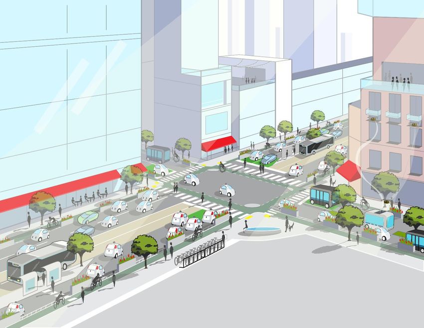
V2I technology allows for DSRC-equipped vehicles (connected vehicles) to communicate with surrounding
DSRC roadway infrastructure. This communication technology has the ability to alert drivers of safety
risks, reduce congestion, send environmental hazard alerts, and reduce the consumption of fuel and
electricity. Below are some examples of V2I applications that improve safety, mobility, the environment,
and agency data/operations to help with an understanding of how this technology can improve the
transportation system and user experience.
Safety is the highest priority of V2I applications. In addition to enhancing vehicular safety, the
implementation of V2I safety applications can help to increase the awareness of, and safety for, nearby
bicyclists and pedestrians. According to PennDOT’s 2017 PA Crash Facts and Statistics, pedestrian- and
bicycle-related crashes represented 4.2% of the total reported crashes in 2017; however, they accounted
for 14% of all traffic fatalities. It is anticipated that implementation of related V2I applications may result
in a significant reduction in the number of bicycle and pedestrian fatalities.
V2I Safety applications currently being tested and under development include:
Red Light Violation Warning – This application would notify connected vehicles approaching a DSRC-
equipped intersection regarding the signal phase and timing, intersection geometry, and position
correction information. If the vehicle is predicted to violate the traffic signal (e.g., run a red light), the
driver would receive a warning sufficiently in advance of the intersection to avoid a violation and potential
crash.
Stop Sign Gap Warning – This application is intended to alert drivers stopped at a stop sign on a side road
of unsafe gaps between vehicles traversing on the major road. If there is insufficient sight distance
between vehicles, a vehicle OBU may not be able to receive messages from other vehicles traveling in
different directions, therefore an RSU would be required to transmit the message of an oncoming vehicle.
This application may be configured to either detect oncoming connected vehicles and then relay a
message directly to the stopped vehicle, or the application can utilize current traffic data collection
Page 9 of 33equipment (e.g., vehicle detectors) to detect all oncoming vehicles and relay the message to a roadside
sign to alert the driver of insufficient gaps or potential collisions.
Pedestrian Warning – This application would notify connected vehicles of the presence of pedestrians in
or approaching the roadway at DSRC-equipped locations (locations with pedestrian activity, signalized
intersections, trail crossings, etc.) through activation of a pedestrian push button. This application may
have the ability to provide day-one benefits to connected vehicles as it does not rely on interaction with
other connected vehicles. Future detection methods for this application may include the use of smart
phones to broadcast their locations, or systems that detect pedestrians in the crosswalk.
Curve Speed Warning – This application would assist drivers in avoiding lane departure crashes by
notifying connected vehicles of an upcoming curve and providing an alert or warning to the driver when
the vehicle approach speed is too high to safely traverse the curve(s).
Spot Weather Information Warning – This application is designed to warn connected vehicles of
inclement weather or adverse roadway conditions by providing an onboard alert or posting a message on
a roadside sign. This application is intended to notify drivers of the need to reduce speed or divert from
their route for multiple types of weather conditions, such as fog, high winds, surface conditions (snow,
ice, rain, flooding), or reduced visibility.
The following are Multi-Modal Intelligent Traffic Signal System (MMITSS) applications that may increase
mobility through corridors in which they are installed by enabling equipped priority vehicles such as public
transit, freight, and EMS to travel through the corridor more efficiently. This is typically accomplished by
modifying existing signal operations at equipped intersections.
Transit/Freight Signal Priority – This application would provide designating signal priority for equipped
transit and freight vehicles. For example, the traffic signal may be adjusted to switch to the phase that will
allow for the transit vehicle to pass through the intersection. This application would typically be utilized
on signalized corridors with a high amount of transit and/or freight traffic.
Emergency Vehicle Preemption Priority – This application would facilitate safe and efficient movement
of emergency vehicles through intersections by clearing queues, stopping/holding conflicting traffic, and
clearing congested traffic. DSRC would allow for ‘network-based’ pre-emption, where connected vehicles
(CVs) communicate within the network to efficiently prioritize emergency vehicles.
Intelligent Traffic Signal (ITS) System – This application would use both vehicle location and movement
measurements of connected vehicles to improve traffic signal operations. The higher the proportion of
connected vehicles in the traffic stream, the more accurately the Intelligent Traffic Signal System would
respond to the traffic demand. This application would typically be utilized on signalized corridors with
high amounts of congestion.
Page 10 of 33Increasing efficiency of vehicular travel has environmental impacts by reducing fuel and electricity
consumption. The following V2I application increases efficiency by reducing headways and delay at
signalized intersections.
Eco-Approach and Departure at Signalized Intersections – This application would use signal phasing and
timing information combined with the connected vehicle location and speed information to provide
suggested speed advice to drivers. Drivers can then adapt their travel speed in order to pass the next
signal on green or to decelerate to a stop in an eco-friendly manner. In congested conditions, this is only
effective if vehicles ahead of the driver are responding similarly, hence, this application would see greater
benefits in a fully penetrated environment.
V2I applications based on data collection from connected vehicles may use this data to create a more
efficient and safer roadway network by allowing for alternate solutions to current traffic detection
methods, traffic modeling, and maintenance needs.
Probe-based Pavement Maintenance – This application would detect vertical wheel movement and/or
body acceleration from connected vehicles to measure road quality. This allows for the detection of
potholes (location and size) and surface roughness.
Traffic Monitoring – This application may allow agencies to reduce or phase out current traffic detecting
methods such as loop detectors and cameras. To replace current detection at signalized intersections, this
application is only viable in a fully penetrated environment. For traffic modeling or monitoring, connected
vehicle probe data combined with statistical methods may replace current detectors prior to full
deployment.
Probe-enabled Traffic Monitoring – This application would use connected vehicle technology to generally
evaluate traffic and travel patterns. This would allow for more accurate traffic model baselining and
predictive traffic studies to be done to create more efficient roadways and connections.
Page 11 of 33While V2I applications have the ability to provide day-one safety benefits to CVs, USDOT has stated that
a 30-50% penetration of DSRC equipped vehicles on the roadway can have a significant impact on safety
for all vehicles.1 Currently vehicle manufacturers have been a critical part in the development of CV
technology. The following case studies provide insight on potential penetration rate scenarios based on
vehicle manufacturer CV deployment rates.
Vehicle Manufacturer Case Study
Over the past 13 years, Toyota has collaborated with other automakers, infrastructure organizations,
and the USDOT to further develop DSRC technology and has stated that most of their models will have
DSRC capabilities by “mid-2020s.” 2 Based on this information, Figure 3 presents a potential DSRC
penetration rate for Toyota’s vehicles on the roadway in the United States.
Figure 3 – Toyota DSRC Penetration Scenario
*Median vehicle fleet age estimated to be 11.5 years. Therefore, assume an additional 23 years for turnover of the existing
fleet
General Motors will likely have a similar DSRC penetration rate to Toyota’s. Currently, General Motors
equips a single Cadillac model with DSRC (CTS Sedan). The automaker plans to introduce the technology
in a crossover vehicle by 2023 and eventually expand the technology across Cadillac’s entire portfolio.3
General Motors and Toyota alone comprised over 30% of the total vehicles sold in the United States in
2018. In addition, other vehicle manufacturers have similar plans and timelines for implementing DSRC
within their vehicles.
1
Source: https://ecfsapi.fcc.gov/file/60001841106.pdf
2
Source: https://corporatenews.pressroom.toyota.com/releases/toyota+and+lexus+to+launch+technology+connect+vehicles+infrastruct ure+in+u+s+2021.htm
3
Source: http://gmauthority.com/blog/2018/06/cadillac-plans-to-bring-v2x-technology-to-new-crossover-by-2023/
Page 12 of 33The following scenarios have been described regarding mixed fleet and full fleet penetration of DSRC.
While related to V2I applications, mixed fleet and full fleet are defined as:
Mixed Fleet – The combination of unequipped and DSRC equipped vehicles on the roadway
Full Fleet – All vehicles on the roadway are DSRC equipped
Urban Corridor
In an urban environment scenario, a highly urbanized, signalized corridor that is prone to congestion and
traffic problems is expected. This type of corridor provides ample infrastructure in place for deployment
of RSUs for V2I applications. In a typical urban corridor, there are many applications (as described in
Section 1) that could be deployed with benefits realized on day-one. This means the driver of a connected
vehicle could receive information immediately to help them make better decisions as they travel through
the corridor.
Many of the applications are focused on signalized intersection operations because they typically require
minimal infrastructure updates to implement. These applications can be deployed to operate in a local
mode, without it being necessary to have backhaul communication in place. The age of the existing signal
controller is the primary limiting factor prohibiting easy implementation.
Mixed Fleet
In a mixed fleet environment, vehicles that are equipped with OBUs will benefit the most, but safety will
be improved for all vehicles on the roadways. The infrastructure RSUs will be providing SPaT information
to aid the driver in reducing potentially unsafe driving actions. As described in Section 2.1, the Red Light
Violation Warning application is one scenario that provides a driver with a warning if they are projected
to run the red light.
The Pedestrian Warning is another application that could be realized by utilizing SPaT information to
inform the driver that the pedestrian push button has been activated.
With deployment of OBUs on emergency, transit, or freight vehicles, signal preemption or prioritization
could be implemented along the corridor to maximize throughput without requiring other passenger
vehicles to be a connected vehicle.
Full Fleet
In a full fleet scenario on the roadway, V2I applications will substantially improve both mobility and safety
as they begin to alter traffic operations (eco-approach, for instance) and significantly reduce driver error.
The Intelligent Traffic Signal System (I-SIG) application can utilize vehicle data collected to create
predictions of lane-specific platoon flow, platoon size, and other vehicle arrival characteristics. The real-
time data availability has the potential to transform how traffic signal systems are designed, implemented
and monitored. Developing new systems that use data obtained from V2V and V2I communications to
control signals in order to maximize flows in real-time can improve traffic conditions significantly. The I-
SIG in a full fleet scenario could play the role of an over-arching system optimization application, that
Page 13 of 33accommodates transit and/or freight signal priority, emergency vehicle preemption, and pedestrian
movements to maximize overall arterial network performance.
Rural Corridor
In a rural environment scenario, a typical corridor would be a low-volume, two-lane highway. There would
be few signalized intersections, two-way stop sign intersections, and limited Intelligent Transportation
System infrastructure. Vehicles may form platoons due to limited traffic, while roadway curvature and
weather-related incidents are to be expected. Therefore, the focus for V2I in rural corridors is geared
more toward safety rather than mobility. The rural environment causes deployment of RSUs to be more
involved due to the lack of existing infrastructure and available power. Communications pose a problem
in rural corridors due to winding roads, mountains and valleys. Cellular service is often nonexistent and
getting long distance line of sight radio systems is problematic. A clear line of sight for DSRC radios will
be crucial for reliable communication. RSU installations should be in appropriate locations in advance of
the point where a vehicle must react to the anticipated application.
Applications best suited for a rural scenario are motorist advisories and warnings, such as speed zone
warnings or curve speed warnings. These applications may be deployed in a local mode by providing a
fixed message to the vehicle without it being necessary to have backhaul communication in place
(communication to a center for data reception, collection and distribution for remote management and
data processing).
Although for some applications, backhaul communications is not necessarily required, many widescale
deployment of rural applications may be limited based on available power, backhaul network availability
and funding to build out the infrastructure required to deploy applications requiring real time data inputs,
like those required in the Spot Weather Warning application.
Mixed Fleet
In a mixed fleet environment there will be some safety benefits to vehicles that are equipped with OBUs,
as the infrastructure is broadcasting information to the vehicle. These applications (speed zone and curve
speed warning) would provide a Traveler Information Message (TIM) to the vehicle allowing the OBU to
determine if the driver is exceeding the upcoming posted speed limit. The OBU would then provide a
warning to the driver.
At two-way stop sign intersections, an appropriate application would be the Stop Sign Gap Assist.
Equipment would need to be installed at stop sign controlled intersections which determines the location
and speed of oncoming vehicles (e.g., using Radar/Lidar). This information, in addition to stop sign
information and intersection map data, is broadcast in the vicinity of the intersection from an RSU. The
vehicle OBU receives this information from the RSU and then provides a warning to the driver.
Full Fleet
In the full fleet environment, a large impact to safety, especially during construction and maintenance
operations, is predicted. Roadwork vehicles can transmit their location through V2V and V2I
communications. This information as well as specific information about roadway impacts can be sent
Page 14 of 33directly to approaching vehicles, thus allowing the driver to move out of a closed lane or reduce their
speed through a work zone. Secondary crashes have the potential to be significantly reduced under a full
fleet environment.
RSUs at strategic locations with backhaul communications would allow additional applications that could
collect passing vehicle data and then provide metric information to roadway agencies. Data such as traffic
volume, probe-based traffic monitoring or probe-based pavement maintenance data could then be
analyzed to further improve the roadway.
Based on the expected timeline for DSRC-equipped vehicle penetration on the roadway, planning for a
mixed fleet in urban and rural scenarios is essential.
While planning for connected vehicles, current systems need to be assessed to determine if they are
compatible with CV requirements (i.e. Internet Protocol version 6 (IPv6), Power over Ethernet (PoE)
capable, etc.). Based on the system compatibility, funding can be planned to upgrade the existing
equipment to support a CV environment and deployment of CV technology (DSRC RSU). While identifying
the status of existing assets, corridor prioritization based upon crash history, congestion, pedestrian use,
bus routes, etc., can be conducted (further discussed in Section 2.3). With this evaluation and ranking of
corridors, deployment of CV equipment can be planned to maximize use of funding for both urban and
rural roadways.
Long-term planning should include routine evaluations of the technology, often referred to as State of the
Practice studies. These evaluations would aid in providing knowledge of any potential changes to the
national CV environment and allow for an analysis on impact to the region. When establishing a long-
term plan for CV deployment, it is beneficial to consider including installation needs in other construction
projects to potentially reduce costs (for example, infrastructure installation to a roadway improvement
project).
As part of this planning effort, it is suggested that MPOs participate at the state level in any committees
related to CVs and AVs. This is an opportunity for MPOs to help shape CV/AV policies and to provide the
state with local concerns and input.
Page 15 of 33Criteria have been developed to assist in the planning of future V2I deployments in both rural and urban
areas. The first step will be to apply the Initial Criteria to narrow down the numerous corridors in the
region. The identified corridors can then be evaluated based on additional criteria (urban and rural) to be
selected as per the user’s interests. Identified corridors can be prioritized further by their existing
infrastructure and alignment with the Transportation Improvement Program (TIP) and traffic impact study
required improvements.
The DSRC Corridor Selection Interactive Map can be used to prioritize corridors in District 8-0 by selecting
various overlapping layers. The map provides a pre-set layer that includes the initial criteria, zero-to-one-
foot shoulders, and bicycle/pedestrian crash locations. In addition to the pre-set layer, other various
criteria are able to be toggled on and off based upon the user’s interest to select corridors. The map can
be accessed at http://arcg.is/1Cnz45
1. Non-Freeway – Freeway use cases are very defined. Corridors/signalized arterials are capable of
many different V2I applications, making them more suitable for early V2I development. While
there are some very important Freeway applications, for the purposes of this effort, the focus will
be on Non-Freeway segments to increase local involvement and to include bicycle and pedestrian
applications.
2. Federal-Aid System – The majority of V2I deployments may qualify for similar federal-aid
programs as ITS deployments (if the deploying agency meets certain eligibility requirements).
a. Ask the question, “where can I put federal dollars?”
The federal-aid roads in the GIS map were obtained through PennDOT.
1. Safety – A high concentration of the following crashes indicates that the corridor would be a prime
candidate for V2I deployment.
a. Red-light violation crashes (Angle, Head-on)
b. Intersection proximity crashes
c. Bicycle/Pedestrian crashes
2015-2017 crash data was obtained from querying the Pennsylvania Crash Information Tool (PCIT)
for each specified criterion.
2. Transit/Bus Route – By applying V2I technology to signalized intersections with transit signal
priority, priority decisions can be optimized while considering vehicle type, passenger count, or
adherence to schedule. Signalized intersections without transit signal priority on a transit/bus
route should be considered for the addition of the transit signal priority V2I application. Transit
routes were obtained through each of the transit providers in District 8-0.
Page 16 of 333. Freight network – A freight network indicates that there is a diverse fleet of vehicles utilizing the
corridor, which allows for diverse applications of V2I technology. The District 8-0 freight network
and freight candidate routes were obtained by contacting PennDOT.
4. Emergency Facility Locations – Applying V2I technology to frequent emergency vehicle routes
would allow for signal preemption to emergency vehicles and the accommodation of multiple
emergency requests. Frequent emergency vehicle routes may be identified by the corridor’s
proximity to emergency resource locations. EMS and fire department locations were obtained
through each County in District 8-0.
For MPOs that maintain a Congestion Management Process, if select corridors are identified as “high
priority congested corridors” and conveyed to TCRPC, TCRPC can add this as an additional layer on the
interactive map.
1. Mix of 2-way stop and signals – This would allow for a diverse set of V2I applications to be
implemented with a minimal amount of infrastructure upgrades.
2. Curvature of roadway – The implementation of V2I technology at curves has the potential to
reduce the number of roadway departure crashes. In 2017, there were 23,023 (18.0%) reported
crashes in Pennsylvania related to the curvature of the road (2017 PA Crash Facts & Statistics
Book). 2015-2017 curve crash data was obtained from querying PCIT.
3. Spot weather issues (reoccurring bad weather crashes) – With a significant number of reported
crashes in Pennsylvania occurring during inclement weather conditions, V2I applications related
to spot weather issue crashes have the potential to greatly reduce crashes due to local hazardous
weather conditions by relaying local weather data to roadside equipment. In 2017, there were
25,406 (19.8%) reported crashes in Pennsylvania which occurred during inclement weather
conditions (2017 PA Crash Facts & Statistics Book). Weather-related crash data from 2015-2017
was obtained from querying PCIT.
4. Corridors with shoulders less than 1 foot – Implementation of V2I technology at defined
locations of departure crashes has the potential to provide additional safety countermeasures
to standard road departure safety improvements. In 2017, there were 37,892 (29.6%) reported
hit fixed object crashes in Pennsylvania (2017 PA Crash Facts & Statistics Book). In addition,
comparing shoulder width data with speed limit data would allow for narrowing down roadways
with minimal shoulders. District 8-0 shoulder width data was obtained by contacting PennDOT.
If the selected corridor has existing compatible infrastructure and is aligned with the TIP, it is a prime
candidate for implementation of V2I applications. If it is not, the desired V2I application may be used to
justify adding compatible infrastructure to future projects.
1. Compatible Infrastructure – Modernized infrastructure already in place could greatly reduce the
cost of implementing various V2I technology, without having to upgrade existing technology. The
two pieces of infrastructure that may have to be modernized are:
Page 17 of 33a. Modern advanced traffic signal controllers (types and model numbers vary by
manufacturer)
b. Robust high-bandwidth backhaul communication system
Municipal fiber locations were obtained through the Traffic Signal Asset Management System
(TSAMS) database. As TSAMS continues to be updated, the municipal fiber locations will become
more refined and accurate. Locations of PennREN fiber was obtained through the PennREN
Network Operations Center and Windstream fiber was obtained through Windstream Enterprise.
2. Alignment with the Transportation Improvement Program (TIP) – Corridors planned for
significant investment in the TIP allow for greater V2I improvement possibilities. Additionally,
projects in the preliminary design stage or before may be able to incorporate V2I applications into
the design. The TIP layers in the DSRC Corridor Selection map show District 8-0 projects currently
on the TIP. These data were obtained by contacting PennDOT.
In planning for the long-term needs of the multimodal transportation system, there are several ways in
which DSRC and related elements can be incorporated into the Long-Range Transportation Plan (LRTP)
planning process. DSRC incorporation is detailed in the following sections related to priority corridor
identification, stakeholder engagement, and plan integration.
A corollary to selecting the appropriate selection criteria in urban and rural areas will identify priority
corridors or networks as a criterion in DSRC investment. The DSRC Corridor Selection Interactive Map
outlined in the previous section of this Guide should be used as a starting point for MPOs in identifying
corridors or roadways where investments in DSRC and related technology should be included as projects
are implemented. These priority networks would become part of the LRTP and would be factored into
the project scope of work when projects are selected within the corridor for maintenance, mobility or
safety improvements.
Ensure operational interests are represented on the plan steering committee – LRTPs are typically
guided by various multimodal transportation interests. As planning for highway transportation continues
to segue from capacity building to more of an operations focus, these interests should be at the table as
the plan is being updated. Related plans such as the Regional Operations Plan, TSMO Strategic Plan, and
Congestion Management Process, should also be consulted as the LRTP is being updated for currency and
to ensure the plan is drawing from the latest thinking as it pertains to transportation operations.
Emphasize DSRC and operations in scenario planning – LRTPs may also consider multiple futures as part
of an exercise in scenario planning. The plan may be used to convey the impacts that different courses of
action could have on financing, land use, and capacity building versus operations or investments in DSRC.
Page 18 of 33You can also read