Delivering Object-Based Immersive Video Experiences
←
→
Page content transcription
If your browser does not render page correctly, please read the page content below
https://doi.org/10.2352/ISSN.2470-1173.2021.18.3DIA-103
                                                                                         © 2021, Society for Imaging Science and Technology

Delivering Object-Based Immersive Video Experiences
Basel Salahieh; Intel Corporation, Santa Clara, CA, USA, basel.salahieh@intel.com
Wayne Cochran; Intel Corporation, Hillsboro, OR, USA, wayne.cochran@intel.com
Jill Boyce; Intel Corporation, Hillsboro, OR, USA, jill.boyce@intel.com

Abstract                                                               coding solution without compromising the interactivity and 6DoF
     Immersive video enables interactive natural consumption of        capabilities of immersive media content. One of MIV operating
visual content by empowering a user to navigate through six            modes is the object-based immersive video coding which enables
degrees of freedom, with motion parallax and wide-angle rotation.      novel use cases for objects within the immersive content at the
Supporting immersive experiences requires content captured by          encoding and decoding stages.
multiple cameras and efficient video coding to meet bandwidth and      In this paper, we first show an example immersive video sequence
decoder complexity constraints, while delivering high quality video    with the generated object maps. Then we discuss the novel use
to end users. The Moving Picture Experts Group (MPEG) is               cases enabled by our object-based coding scheme. Afterwards we
developing an immersive video (MIV) standard to data access and        explain the design of object-based MPEG immersive video coding
delivery of such content. One of MIV operating modes is an object-     and how it is implemented in the Test Model for Immersive Video
based immersive video coding which enables innovative use cases        (TMIV) [3], the reference software of MIV. The quality
where the streaming bandwidth can be better allocated to objects       improvement as well as the bandwidth saving, and the performance
of interest and users can personalize the rendered streamed            gain of the object-based solution are evaluated.
content. In this paper, we describe a software implementation of
the object-based solution on top of the MPEG Test Model for
Immersive Video (TMIV). We demonstrate how encoding
foreground objects can lead to a significant saving in pixel rate
and bitrate while still delivering better subjective and objective
results compared to the generic MIV operating mode without the
object-based solution.                                                 Figure 1. Immersive media capture, platform, and playback stages delivering
                                                                       6DoF experience

Introduction
Advancements in digital media technology are enabling worldwide
adoption of immersive media by bringing innovative six Degrees         Immersive Video Content Sample
of Freedom (6DoF) visual experiences of immersive media                One of the synthetic content sequences, called Museum [4], used
formats, such as multi-view video, point-cloud video and               during the MIV development process has been utilized here. We
volumetric video, to mass-consumer market. By enabling 6DoF            first describe the sequence and its object maps that we have
with motion parallax and wide-angle rotation capabilities, an          generated from it to showcase the object-based solution.
immersive media platform shown in Fig. 1 allows viewers to
                                                                       Museum Content
navigate the content in a more natural, personalized and interactive
                                                                       The dataset represents a time-sequence of 300 frames, where each
way.
                                                                       frame contains 24 views rendered from 24 virtual cameras each
A complete real-time immersive media platform includes
                                                                       directed normal outward to a sphere, see figure 2-left. Each view is
everything from the capturing of immersive content to the
                                                                       made up of a 2048x2048 texture image and a corresponding16-bit
production, processing, and delivery of immersive visual
                                                                       depth image (see Figure 2-right) stored as equirectangular
experiences and services. For a real-time immersive media
                                                                       projections with a 180-degree vertical and horizontal field of view.
platform, it is difficult to move large amounts of captured media
                                                                       Camera position, orientation, and projection information are
data along a media processing pipeline with minimal latency,
                                                                       provided for all 24 views.
compute the immersive media data efficiently with resource
constraints, and deliver the best possible quality of media content
over limited network bandwidth. Given those challenges, such
immersive experiences have previously been limited to virtual
videos, pre-synthesized at the capture side, where the content
creator determines the navigation path, renders ordinary 2D video
for the navigation path, and distributes content using legacy video
distribution methods.
The coded representation of immersive media being developed by
the Moving Picture Expert Group (MPEG), is part of the MPEG-I
[1] project, which is an industry effort to develop a suite of
standards to support immersive media access and delivery. By
                                                                       Figure 2. Capturing camera system composed of 24 cameras (left) along with
leveraging the state-of-art high efficiency video compression          the texture and depth components of one of the views at a given frame
technologies, e.g., HEVC, MPEG Immersive Video (MIV) [2], one
of the MPEG-I standards, is promising to deliver a standard-based

IS&T International Symposium on Electronic Imaging 2021
3D Imaging and Applications 2021                                                                                                           103-1
Object Maps                                                                object-based coded representation, encoder may use contextual
Our object-based coding solution requires input information which          information available to it to decide the relative importance of
indicates which object each pixel within a view per frame belongs          different objects and provide object-based scalability for adaptive
to. This can be provided in a form of supplemental object maps             streaming. For example, unimportant objects, e.g., objects too far
associated with the content. For the Museum sequence, the object           away from a viewport, can be dropped entirely or compressed at
maps feature 25 different objects indexed as illustrated in Fig. 3.        lower visual quality. The quality for objects that are important to
Note that for this content, ObjectIDs [0, 5] are reserved for the          the viewers does not degrade even at lower network bandwidth.
background objects while ObjectIDs [6, 24] are reserved for all
other foreground objects in the scene. The generation of these
                                                                           Objects of Interest
object maps is further explained in appendix A.1.                          Object-based coded representation also allows highly personalized
                                                                           content because each object can be compressed in different visual
                                                                           quality. If one is interested in a specific object, one can select the
                                                                           stream with the object-of-interest encoded in higher visual quality.

                                                                           MPEG Immersive Video Coding
                                                                           The immersive video format that is input to a MIV encoder is a
                                                                           multiplicity of synchronized view videos captured by real and/or
                                                                           virtual cameras that can be arranged in a variety of configurations,
                                                                           including outward-facing, inward-facing, or a planar camera array.
                                                                           The content can be synthetic (i.e. computer generated) or natural
                                                                           (i.e. real-world) and in 360 degree (e.g. equirectangular) or
Figure 3. The indexing of Museum’s Object Maps shown in 3D layout (left)   perspective projection format. Each view is composed of two
and color-indexed object map of v5 – frame 100 (right).                    components; a texture content (e.g. RGB / YUV channels) and its
                                                                           associated depth map (whether captured or estimated).
                                                                           The MIV standard [2] is based on the Visual Volumetric Video-
Object-Based Immersive Applications                                        based Coding (V3C) specification and aims at exploiting
The object-based coded representation of immersive media enables           redundancy between the views and leveraging state-of-art video
many novel use cases for volumetric video coding and rendering.            codecs to deliver the best quality at minimal bandwidth and with a
In addition, it helps addressing several MPEG requirements for             minimum requirement of decoder complexity. The MIV standard
immersive media access and delivery [5] including the                      defines the format of the compressed bitstream and the normative
manipulation of decoded objects at higher level without having             decoding process to deliver the 6DoF experience while TMIV [3],
access to the actual pixel information.                                    its reference software, provides an exemplary full implementation
                                                                           of the encoder and decoder stages. A brief description of the TMIV
Priority Objects Rendering                                                 software is given here to establish the technical background for the
Object-based coded representation of immersive media speeds up             object-based solution described in a later section.
processing of content at the decoding side to meet real-time               The immersive media content streamed in MIV can be navigated
requirements. Each object in the bitstream can be signaled for its         with 6 DoF by a wide range of consumer devices which contain
priority over the rest of the objects. When such object priority           video decoding hardware and a GPU, such as computers with face
information is available at the decoder side, the renderer can             tracking camera, smartphones/tablets with inertial sensors, head-
choose to process the high priority objects only while dropping low        mounted displays, volumetric and multi-view displays.
priority objects to meet latency or computing constraints.
                                                                           TMIV Encoder
Objects Filtering                                                          The TMIV encoder takes as inputs texture and depth videos for
Since each object is coded individually, viewers may choose to             multiple synchronized source views, each at a particular position
view only the objects of interests while not displaying the other          and orientation. The input views are processed using reprojection
objects. Object-based coded representation not only allows such            between views to remove redundant regions, in order to reduce the
kind of personalized viewing on the decoder side but also allows           bitrate and pixel rate needed to represent the whole content.
the encoder to pack only objects of interest in the bitstream in the       The TMIV encoder identifies a few of the views as basic views,
event of limited network bandwidth or supporting less capable              each of which is fully encoded within a single patch. The
client devices.                                                            additional views are then projected against the basic ones (and
Background Rendering                                                       previously pruned ones) to extract the non-redundant information
In object-based code representation, background is considered to           in a form of rectangular patches and pack them into atlases
be a special object that can be rendered by itself independent of          (composed of texture and depth components) during the atlas
other objects. The background object can be synthesized from               construction process. Occupancy maps are also generated to
virtual / pre-rendered content. For example, the venue of a sports         indicate the active pixels (for the non-redundant regions) per patch
game can be synthesized as a 3D model ahead of a live game and             and helps resolving overlapped patches later at the decoding stage.
used for rendering as the background in a scene augmented with             The occupancy maps are embedded within the lower range of the
objects (players, balls, etc.) captured from the live game.                depth component of the atlases. The atlases are finally encoded
                                                                           using the existing HEVC video codec. The associated view
Object-Based Scalability                                                   parameters list (illustrating how views are placed and oriented in
Traditional adaptive streaming technique alters the quality of entire      the coordinate space) and the atlas data (indicating how patches are
video stream in order to fit to different network conditions. In           mapped between the atlases and the views) are carried as metadata

                                                                                         IS&T International Symposium on Electronic Imaging 2021
103-2                                                                                                          3D Imaging and Applications 2021
within the bitstream. The encoding process of a simplified TMIV        Object-Based Encoder
software is summarized in Fig. 4 while example atlases are shown       The modified TMIV encoder features an object-based atlas
in Fig. 7.                                                             constructor which is illustrated in Fig. 6. All other blocks are left
The TMIV encoder attempts to optimize bitrate, to reduce the           unmodified as in the original TMIV encoder. Note that in the
network bandwidth requirements, and to optimize pixel rate, which      object-based solution, object maps for all views and frames are
directly impact decoder complexity requirements. Pixel rate is         made available as an input as well in addition to the texture content
calculated as the resolution of the combined atlases multiplied by     and depth maps. Also, the basic views here are just used for
the frame rate.                                                        pruning and packing but not being streamed since each patch shall
                                                                       carry only pixels that belong to a specific object. Some
                                                                       components of the atlas constructor operate on frame level while
                                                                       others on intra-period level (i.e. random-access period).

Figure 4. Flow diagram of a simplified TMIV encoder

TMIV Decoder
At the decoding stage, video decoding is applied to retrieve the
atlases, the metadata is parsed, and the occupancy maps and block
to patch maps (indicating patchIDs of each pixel in the atlas) are
recovered. The renderer then within the exemplary TMIV decoder         Figure 6. Flow diagram of an object-based atlas constructor inside TMIV
outputs a perspective viewport, selected based upon a viewer’s         encoder
position and orientation, generated from the decoded atlases and
metadata of the immersive decoder. The TMIV rendering process
is illustrated in Fig. 5 which includes a patch culling step to        Frame Level Operations
exclude all patches that do not contribute to the viewport, a          The object-based atlas constructor takes as an input the texture,
geometry process to retrieve the geometry at full resolution and       depth, and object maps of the frame being processed in addition to
find the metric depth, the reconstruction of pruned views, the         what views being labeled as basics along with their camera
unprojection and reprojection to the target viewport, the merging      parameters. A loop is established over the objects selected for the
and inpainting steps. The complexity of the TMIV decoding              encoding (whether preset by a user or decided based on an
process is largely driven by the pixel rate. Note that the MIV         encoding metric) where in each iteration the related object layers
standard [2] itself does not specify the reference renderer but        are extracted from the frame’s views (texture and depth) and
supplies it with the required metadata and decoded content.            passed to the pruner which finds the nonredundant parts and
                                                                       returns the related binary masks. Note that the looping over the
                                                                       pruner can be parallelized over various objects since there is no
                                                                       dependency and to maintain reasonable encoding time.
                                                                       The pixels of the basic views’ masks by default (i.e. in the original
                                                                       atlas constructor) are turned on (i.e. set entirely to max grey level)
                                                                       denoting that the entire basic views are streamed in whole patches.
                                                                       However, for the object-based implementation no patch can have
                                                                       pixels belong to more than one object at a time. Thus, the basic
                                                                       masks are updated in the object masker based on the object maps
                                                                       such that pixels are turned on only for pixels belong to the
                                                                       extracted object. The other pruning masks are refined as well to
Figure 5. Flow diagram of a simplified TMIV renderer
                                                                       accurately represent the object. Then object masks are formed such
                                                                       that the related objectID is assigned to all “on” pixels within the
                                                                       refined masks (across all views) for the frame being processed.
Object-Based Implementation in TMIV                                    The object masks are merged with those in the previous iteration,
As the encoding and decoding stages of the TMIV software have          this way objectID can be tracked and patches can be tagged with
been introduced, we explain here the modifications added on top of     the right objectID label at a later stage. The object layers resulted
the software to bring the object-based capabilities to it. Note that   from the object separator stage are also merged together and
the TMIV software including the object-based solution is               pushed into a buffer so they can be used in the atlas generation
accessible publicly on the Gitlab server at https://gitlab.com/mpeg-   stage. The aggregator then aggregates the pruning binary masks
i-visual/tmiv/.                                                        and the merged multi-level object masks to account for motion
                                                                       across frames within an intra-period.

IS&T International Symposium on Electronic Imaging 2021
3D Imaging and Applications 2021                                                                                                       103-3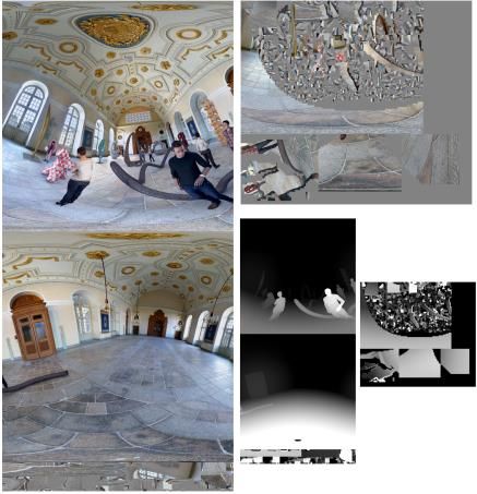
Inter-Period Level Operations
After processing all frames within an intra-period (i.e. random-                      MIV Coding – A97                     Object Coding – E97
access period), the aggregator terminates the accumulation of the
masks and passes them to the patch packer. The aggregated object
masks are then used to filter out the binary masks, so clustering is
applied per object and the resulted clusters are tagged with the
related objectID and queued together. After clustering over all
objects, the clusters are ordered based on how many active pixels
they include (unless they belong to the basic views). Patches are
then formed from the clusters and packed into the atlases. Note that
each patch carries the same objectID of the cluster that initiated it.
Finally, an atlas generator is deployed to write the texture and
depth content of the patches. The content of a given patch is
extracted from the associated object views passed by the object
masker and merger block.
Object-Based Decoder
The TMIV renderer has been modified to support the object-based
filtering and rendering operations, although block-wise it remains        Figure 7. TMIV encoder results (shown for frame 2) for MIV anchor (left)
as illustrated in Fig. 5 (but now the object filtering block will be in   including 2 atlases and encoding full-content and for object-based coding
                                                                          results (right) including 1 atlas encoding only foreground objects.
used). The user can pick a desired set of objects to be rendered,
and the block to patch map per atlas is updated such that the
patchIDs of patches that carry objectIDs of excluded objects are set
                                                                          Three objective metrics are used for the evaluation according to the
to unoccupied. This way the renderer ignores them when
                                                                          CTC: the weighted-to-spherically uniform PSNR [7], the Video
synthesizing the desired viewport. Since pixels of filtered out
                                                                          Multimethod Assessment Fusion (VMAF) [8], and the Immersive
objects might be still occupying pixels in the rendered viewport,
                                                                          Video PSNR (IV-PSNR) [9]. The objective results of the delivered
the inpainter assumes missing info and try to fill them causing
                                                                          quality vs bitrate for various quantization points (QPs) are
stretched artifacts. Thus, in this implementation we are bypassing
                                                                          illustrated numerically in table 1 and as curves in Fig. 8. Note the
the inpainter for inactive pixels outside the rendered objects and
                                                                          significant saving in bit distortion rates across various metrics
simply fill them by a neutral color.
                                                                          (~46% in PSNR, ~57% in VMAF, and ~56% in IV-PSNR) when
                                                                          excluding the background content. Also, in terms of the processing
Object-Based Video Coding Study                                           time the rendering speed of the foreground objects here is nearly
A Common Test Conditions (CTC) [6] procedure has been                     double the speed when rendering the full content.
established by the MIV group to evaluate improvements and
solutions proposed for immersive video coding. We follow the
                                                                          Table 1. Objective results (in terms of low & high bit distortion
CTC guidelines and report below the objective and subjective
                                                                          rates of various metrics) showing the gain when foreground
results of object-based coding (encoding foreground objects only)
compared to the MIV anchor (i.e. encoding full-content but using          object coding is used compared to the MIV anchor.
the ordinary MIV operation mode). For the object-based coding,
we only select the foreground objects to be encoded and reduce the
number of outputted atlases to 1. The study is conducted using
TMIV software-version 7.2.
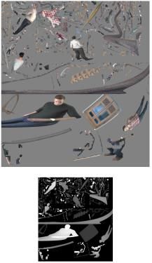
In terms of encoded atlases, the MIV anchors encoding full content
requires 2 atlases (of texture size 2048×4352 and 2048×1824)
however the object-based solution requires only 1 atlas (of texture
size 2048×2272) for encoding foreground objects resulting in
~65% saving in pixel rate. The atlases of both approaches are
shown in Fig. 7. Note how in the object-based solution, patches
packed in the atlas only include content of a single object per each.
Also, there is no basic view being streamed yet the patches coming
from the basic views are prioritized during the packing process.
The atlases are HEVC video encoded following the CTC
guidelines and decoded accordingly. The block to patch maps are
filtered to keep foreground objects as well. The rendered views
have no background content hence the objective metrics are
computed with background pixels being masked out to get an
unbiased objective comparison. In other words, object maps are
used to mask both the reference source views and the reconstructed
ones such that background pixels are substituted with neutral grey.
The masking procedure is also applied to MIV anchor’s rendered
views so only the foreground object pixels are included, for a fair
comparison with the object-based coding results.

                                                                                        IS&T International Symposium on Electronic Imaging 2021
103-4                                                                                                         3D Imaging and Applications 2021
Figure 9. Subjective results of object-based solution compared to MIV anchors
                                                                                showing a zoomed version of v5-frame 2 of MIV anchor-QP5 (top) and object-
                                                                                based coding -QP3 (below). Note the subjective results are shown for different
                                                                                QPs but with nearly matched bitrate.
Figure 8. The rate-distortion curves of object-based solution (dot dashed red
curves) compared to MIV anchor (dashed blue curves) using masked Y-PSNR
(luma channel only) (top), masked VMAF (middle), and masked IV-PSNR
(bottom).
                                                                                Conclusion
                                                                                An object-based coding solution is introduced into the MPEG
                                                                                Immersive Video (MIV) to enable innovative immersive
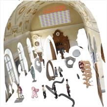
Figure 9 shows subjective comparison between MIV anchors &
                                                                                experiences including efficient bandwidth utilization for encoded
object-based coding results at 3rd frame of v5 [6] at nearly matched
                                                                                objects of interest and personalized rendering of selected objects
bitrate. We can see better subjective results (e.g. more details on
                                                                                on synthesized background. A software implementation is
faces of the actors, fine textures on the snake-shaped sculpture) in
                                                                                available in the Test Model for MPEG Immersive Video (TMIV)
the object-based coding case. There are two key reasons why the
                                                                                for both the encoding and decoding stages. The solution produces
object-based coding produces better subjective results. The first is
                                                                                patches that include a content for a single object per patch,
that by reducing the amount of content to be coded by excluding
                                                                                allowing each patch to be associated with an objectID. When
the background areas, the HEVC QP can be reduced while meeting
                                                                                excluding the background objects from the encoded stream of one
the same bitrate. In addition, the artifacts created by HEVC
                                                                                of the MIV sequences (i.e. the Museum sequence), the coding
encoding the depth atlas can be reduced by avoiding having
                                                                                results show a ~65% saving in pixel rate, ~50% gain in bit-
significant differences in depth values within the same patch, e.g.
                                                                                distortion rate, and rendering at nearly double speed as opposed to
foreground and background depth values.
                                                                                encoding and rendering the full content. Reduction of pixel rate
The improvements in subjective quality prove the main motivation
                                                                                enables support for immersive video playback on a wider range of
of the object-based solution where streaming bandwidth can be
                                                                                decoder devices. We also report significant improvement in the
more efficiently geared to deliver the objects of interest in a better
                                                                                subjective quality of object-based solution compared to MIV
quality rather than sacrificing the whole content to fit in case of a
                                                                                anchors which serves as a proof that the streaming bandwidth
limited bandwidth.
                                                                                budget can be better geared toward delivering the objects of
                                                                                interest in a better quality as oppose to a global reduction in quality
                                                                                when streaming the whole content within a limited bandwidth.

IS&T International Symposium on Electronic Imaging 2021
3D Imaging and Applications 2021                                                                                                                       103-5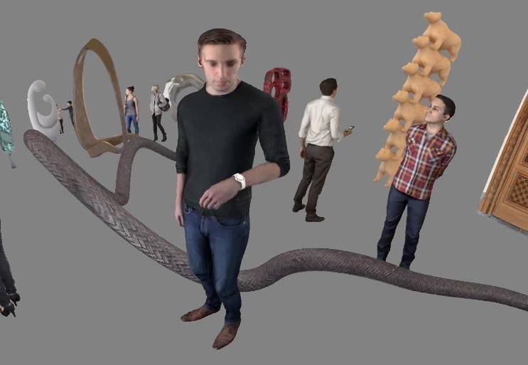
References
[1]   MPEG-I: Coded Representation of Immersive Media. ISO/IEC
      23090.
[2]   J. Boyce, R. Doré, V. K. M. Vadakital (Eds.). Committee Draft of
      MPEG       Immersive     Video.   ISO/IEC      JTC1/SC29/WG11
      MPEG/N19482, July. 2020, Online.
[3]   B. Salahieh, B. Kroon, J. Jung, A. Dziembowski (Eds). Test Model 7
                                                                           Figure 10. Point-cloud recon. from a single frame (left), floor removed (center),
      for MPEG Immersive Video. ISO/IEC JTC1/SC29/WG04 N0005,              background removed (right).
      Oct. 2020, Online.
[4]   R. Doré, G. Briand, T. Tapie. Technicolor 3DoFPlus Test Materials.
      ISO/IEC JTC1/SC29/WG11 MPEG/m42349, April 2018, San Diego,           Per-frame Clustering
      USA.                                                                 After assigning the background pixels their associated objectID,
                                                                           we investigate the labeling for other objects. An object mask (to
[5]   Requirements for Immersive Media Access and Delivery. ISO/IEC
                                                                           contain the resulting cluster labels for each pixel in the frame) is
      JTC1/SC29/WG11 MPEG/N18654, July 2019, Gothenburg, Sweden.
                                                                           initialized and background pixels are labeled. Then an unlabeled
[6]   J. Jung, B. Kroon, J. Boyce. Common Test Conditions for MPEG         pixel is selected as a seed value, and the mask is flood-filled (i.e.
      Immersive Video. ISO/IEC JTC1/SC29/WG04 MPEG/N0006, Oct.             over the connected neighboring pixels) and assigned the next
      2020, Online.                                                        available object label. The flood-fill uses a threshold on the
                                                                           distance between the reconstructed 3D points associated with each
[7]   Y. Sun, A. Lu and L. Yu, “Weighted-to-spherically-uniform quality
                                                                           pixel as the criterion for propagating the label value. This process
      evaluation for omnidirectional video,” IEEE Signal Processing
                                                                           is repeated until all pixels are assigned a label. Note that the mask
      Letters, vol. 24, no. 9, pp. 1408-1412, 2017.
                                                                           not only stores the object labels but also controls the boundaries of
[8]   Z. Li, A. Aaron, I. Katsavounidis, A. Moorthy and M. Manohara,       the flood-fill.
      “Toward a practical perceptual video quality metric,” Netflix        Consistent Labeling
      Technology Blog, 2016.                                               The remaining problem is to find a consistent labeling across views
[9]   “Software manual of IV-PSNR for Immersive Video,” ISO/IEC            and frames. Also, some objects will be divided into multiple pieces
      JTC1/SC29/WG11 MPEG/N18709, Göteborg, Sweden, July 2019.             (e.g. the metallic snake that goes through various objects) which
                                                                           we want to merge and assign a single label as shown in Fig. 11. To
Appendix                                                                   accomplish this, we build a complete point-cloud for each frame
                                                                           using all 24 views and perform a full 3D clustering to define a
Object Maps Generation                                                     canonical label for each object. Each frame’s cluster labels are
Given the intrinsic and extrinsic camera parameters we can                 then remapped to their canonical value by finding the closest
compute the 3D location associated with each pixel in the texture          cluster in the canonical cluster set. Furthermore, since the objects
of a known depth value. Figure 10 - left shows the point-cloud             do not move much within the sequence and are reasonably
constructed from its associated depth and texture images. The              separated, we only compute the canonical clusters for the first
shadow-like holes in the point-cloud result from the large number          frame and carry-out the labeling results across all frames as
surfaces that are occluded from the single camera’s viewpoint. A           opposed to laboriously creating point-cloud clusters for all 300
more complete point-cloud can be created for each frame by                 frames and unifying their label values.
transforming all the point-clouds from every camera into a
common coordinate system. We leverage point-cloud clustering
techniques to segment each frame into its constituent objects as
describe here.
Since the data is effectively noiseless (i.e. synthetic), we can
accurately isolate the various objects in the scene. For a given
frame we reconstruct a point cloud, Fig. 10-left, using the
corresponding ground-truth depth maps and the exact camera
parameters. If we remove the points representing the floor object,
then the segmentation problem of various objects within the frame
is reduced to a 3D connected components problem (i.e.; point-
cloud clustering).                                                         Figure 11. Initial clustering results of shown for v5 - frame 0 (left) and the
Background Removal                                                         refined consistent labeled clusters (right), note that piecemeal clusters are
                                                                           merged to single objects. Note how the snake metal object (behind the person
The floor object can be removed by numerically computing a best            at the center) was broken to 4 pieces initially but combined into one object
fitting plane for the floor geometry via the method of least squares.      label eventually.
We can then cull all points that lie close to the plane, see Fig. 10-
center. By repeating this procedure for the remaining walls and
ceiling we remove the remaining background points, see Fig. 10-            Biography
right. Note that each background object is assigned a unique               Basel Salahieh is immersive media algorithms and standards architect at
objectID which are in the range [0, 5] for the Museum sequence,            Intel (CA, USA) responsible for delivering immersive experiences on intel
illustrated in Fig. 3-left.                                                devices, holding a Ph.D. degree in electrical and computer engineering
                                                                           and M.S. in optical science from the University of Arizona (AZ, USA), M.S.

                                                                                           IS&T International Symposium on Electronic Imaging 2021
103-6                                                                                                            3D Imaging and Applications 2021
in electrical engineering from the University of Oklahoma (OK, USA), and
B.S. in communication engineering from Aleppo University (Syria). His
research interests are related to light fields, point clouds, mixed reality,
and immersive video systems. Basel is also a developer and editor to the
test model of MPEG immersive video.

Wayne Cochran is a software engineer in Intel sports and assistant
professor in Washington State University teaching computer graphics,
compilers, numerical computing, and Mobile App development courses.
Wayne holds a Ph.D. degree in computer science from Washington State
University (WA, USA) and B.S degree in mathematics from University of
Washington (WA, USA).

Jill Boyce is Intel Fellow and Chief Media Architect at Intel, responsible
for defining media hardware architectures for Intel’s video hardware
designs. She represents Intel at the Joint Video Exploration Team (JVET)
of ITU-T SG16 and ISO/IEC MPEG. She serves as Associate Rapporteur of
ITU-T VCEG, and is an editor of the MIV specification. She is an IEEE
Fellow. She received a B.S. in Electrical Engineering from the University
of Kansas in 1988 and an M.S.E. in Electrical Engineering from Princeton
University in 1990. She was formerly Director of Algorithms at Vidyo, Inc.
where she led video and audio coding and processing algorithm
development. She was formerly VP of Research and Innovation Princeton
for Technicolor, formerly Thomson. She was formerly with Lucent
Technologies Bell Labs, AT&T Labs, and Hitachi America. She was
Associate Editor from 2006 to 2010 of IEEE Transactions on Circuits and
Systems for Video Technology.

IS&T International Symposium on Electronic Imaging 2021
3D Imaging and Applications 2021                                               103-7
JOIN US AT THE NEXT EI!

 IS&T International Symposium on

 Electronic Imaging
 SCIENCE AND TECHNOLOGY

Imaging across applications . . . Where industry and academia meet!

• SHORT COURSES • EXHIBITS • DEMONSTRATION SESSION • PLENARY TALKS •
• INTERACTIVE PAPER SESSION • SPECIAL EVENTS • TECHNICAL SESSIONS •

                  www.electronicimaging.org
                                                             imaging.org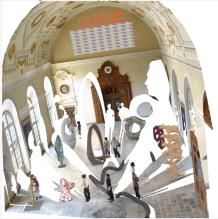
You can also read


