Design and Stability Analysis of a Robust-Adaptive Sliding Mode Control Applied on a Robot Arm with Flexible Links
←
→
Page content transcription
If your browser does not render page correctly, please read the page content below
Preprints (www.preprints.org) | NOT PEER-REVIEWED | Posted: 15 September 2021

 Design and Stability Analysis of a Robust-Adaptive Sliding Mode Control
 Applied on a Robot Arm with Flexible Links
 Çağlar Uyulan1*
 1 Department of Mechanical Engineering, Faculty of Engineering and Architecture, İzmir Katip Çelebi University, İzmir,
 Turkey,
 0000-0002-6423-6720, caglar.uyulan@ikcu.edu.tr

 *Corresponding Author

 Abstract − Modelling errors, robust stabilization/tracking problems under parameter and model uncertainties complicate
 the control of the flexible underactuated systems. Chattering-free sliding-mode based input-output control law realizes
 robustness against the structured and unstructured uncertainties in the system dynamics and avoids excitation of
 unmodeled dynamics. The main purpose is to propose a robust adaptive solution for stabilizing and tracking direct-drive
 (DD) flexible robot arms under parameter and model uncertainties, as well as external disturbances. A lightweight robot
 arm subject to external and internal dynamic effects was taken into consideration. The challenges are compensating
 actuator dynamics with the inverter switching effects and torque ripples, stabilizing the zero dynamics under
 parameter/model uncertainties and disturbances while precisely track the predefined reference position. The precise
 control of this kind of system demands an accurate system model and knowledge of all sources that excite unmodeled
 dynamics. For this purpose, equations of motion for a flexible robot arm were derived and formulated for the large motion
 via Lagrange’s method. The goals were determined to achieve high-speed, precise position control, and satisfied accuracy
 by compensating the unwanted torque ripple and friction that degrades performance through an adaptive robust control
 approach. The actuator dynamics and their effect on the torque output were investigated due to the transmitted torque to
 the load side. The high-performance goals, precision&robustness issues, and stability concerns were satisfied by using
 robust-adaptive input-output linearization-based control law combining chattering-free sliding mode control (SMC) while
 avoiding the excitation of unmodeled dynamics.

 Keywords − Flexible robot arm, robust-adaptive control, sliding mode control, actuator dynamics, zero dynamics.

 1

 © 2021 by the author(s). Distributed under a Creative Commons CC BY license.
Preprints (www.preprints.org) | NOT PEER-REVIEWED | Posted: 15 September 2021

 1. Introduction
 The fast stabilization and precise tracking of systems (underactuated) are regarded as a hard control
 issue, whose solution will address implementation from space robotics and weapon platforms to the
 control of air/sea/ground vehicles and systems exposed to unpredictable actuator failure [Bergerman
 et.al, 1995; Martinez et.al, 2003]. Control of underactuated systems present challenges even in the
 nonappearance in terms of uncertainty; however, modelling errors and disturbances add to the
 complications due to the active and passive degrees of freedom (DOFs) coupling [Chen&Sun, 2020;
 Han et.al, 2020].

 Many favourable results were presented, addressing robust stabilization and robust tracking control
 problems for classes of underactuated systems offering nonlinear control designs dealing with
 uncertainties. It is important to define and address robust stabilization/tracking issues for classes of
 underactuated systems. The underactuated systems with parametric uncertainties are driven
 through a set of structured nonlinear equations of motion (EOM) that can be exploited for the
 construction of Lyapunov functions to be used in the robustness analysis [Xu&Özgüner, 2008; Ovalle
 et.al, 2019; Rudra et.al, 2016; Tuan&Lee, 2016; Din et.al, 2016].

 The flexible robotic arms constitute an underactuated system due to the structural flexibilities
 leading to a system with higher DOFs than the total number of actuators. The DD flexible robot arm
 system model inherently covers significant flexibility modes, Coriolis, centripetal and gravitational
 effects as well as dynamics of the actuator [Krafes et.al, 2018; Lai et.al, 2019]. Its complex dynamic
 structure arises from the interaction of structural flexibilities and actuator dynamics. The problem of
 modelling error originated from parameter and model uncertainties are solved through precise
 control action that demands very accurate system models and considers all sources that excite
 unmodeled dynamics. Also, the consideration of actuator dynamic effect and torque pulsations is
 critical for high precision demands in DD robotics [Zhou et.al, 2020; Cheah et.al, 2006]. A detailed
 inspection of the existing literature reveals that research on underactuated DD robotic systems
 focused on the flexible robot manipulator control could be divided into two main groups; the first
 one [Aghili et.al, 1997; Jiang et.al, 2017; Petridis&Kanarachos, 2007] covers the research on the high-
 performance control of DD actuators taking only actuator dynamics into account and dealing with
 torque pulsation effects, the second one [Sayahkarajy et.al, 2016; Cambera&Feliu-Batlle, 2017;
 Ansarieshlaghi&Eberhard, 2018] is related to the control of underactuated robot arms, either with
 the consideration of passive joints or flexible links, e.g. single-link flexible arm concentrating on the
 stabilization and tracking the performance of the active and passive DOFs. The utilization of high
 torque is required in the lightweight DD systems that involve the direct coupling of motors with their
 loads, due to the removal of transmission mechanisms, such as gearboxes, belts, harmonic drives etc.
 The joint elasticity, backlash, and friction attenuation, as a result, lead to a system having higher
 servo hardness and improved stabilization characteristics over systems that include gears. This
 structure also provides the actuator to position the shaft more precisely as compared to a geared
 system. The backlash that occurred in the typical gearing contributes to a “dead zone” falling in the
 region of the system null point and reducing the accuracy in the position [Kostic et.al, 2002; Gokasan
 et.al, 1998; Arısoy et.al, 2010; Li&Li, 2013]. [Uechker et.al, 1991] demonstrates that methods based
 on the model achieve two to four times better performance than the PID; [Ayten&Dumlu, 2018]
 addresses the tracking control of a 2 DOF DD arm with adaptive and robust control schemes;
 [Azizi&Yazdizadeh, 2019] presents a systematic comparison of passivity-driven robust solution for a 2
 DOF DD robot arm; [Santibanez et.al, 2005] demonstrates the effect of static friction on the set-point

 2
Preprints (www.preprints.org) | NOT PEER-REVIEWED | Posted: 15 September 2021

 control of a DD system. An important problem with DD actuators is the non-uniform distribution of
 the motor windings, the saliencies in the rotor/stator and their interaction with the winding currents
 giving rise to undesirable torque pulsations. In the literature, they are classified as torque ripple
 [Naayagi&Kamaraj, 2005] and cogging torque [Fei&Luk, 2009] depending on their source. These
 pulsations are directly reflected on the load side, leading to speed oscillations, which cause
 deterioration in the system performance. Torque pulsations cause inaccuracies or instabilities.
 Statically, torque ripples can be accepted as load torque varying via rotor angular position. From the
 dynamic perspective, it can stimulate the unmodeled dynamics which lead to unstable mode
 [Şahin&Öner, 2021; Matsui, 1993]. Therefore in the modelling and control of DD systems, the
 actuator dynamic is combined with the manipulator dynamics, especially when high-performance
 goals are involved. The high-performance goals require using high torque, lightweight DD systems,
 which involve the direct coupling of motors with their loads, due to the removal of transmission
 mechanisms, such as gearboxes, belts, harmonic drives, and so on. In the literature, techniques
 dealing with torque ripple elimination for DD actuators have been proposed [Aghili et.al, 1998;
 Pandya&Chatterjee, 2010]. Some techniques focus on the design of electric motors to achieve the
 production of smooth torque. Although effective for torque ripple minimization, the proposed
 methods are specific to the machine involved and do not offer a flexible solution. Other techniques
 cover the minimization of torque ripple; thereby, taking a more flexible and less costly approach to
 the solution of the problem. Harmonic cancellation is applied through predefined current waveforms
 [Petrovic et.al, 2000]. This method necessitates the torque ripple information of the motor and
 utilizes the model of the torque production to evaluate current waveforms injected for attenuating
 the unwanted torque components. These methods have parameter variation sensitivity and their
 effectiveness are lowering if the conditions change. As a solution to the problem of parameter and
 load uncertainty, [Fei et.al, 2019] uses parameterization techniques to cancel torque pulsations and
 unknown load effects for precise control. [Almakhles, 2020] integrates the integral and backstepping
 SMCs in a double-loop to ensure the position tracking capability subjected to the disturbance.
 [Petrovic et.al, 1998] presents a passivity-based adaptive control for suppressing torque ripple while
 enabling speed control for a permanent-magnet synchronous motor (PMSM). High-speed lightweight
 DD systems also require structural flexibilities to be taken into account for high precision goals. The
 resulting system has a higher number of passive DOFs than active control inputs, thus, should be
 viewed as an underactuated system. They demonstrate nonlinearities, and nonminimum phase
 features, which lead to a hard control problem [Krener, 2015] is a survey on the application of
 geometric nonlinear control. Energy-based approaches [Xin&Yamasaki, 2012] for the stability and
 tracking control of underactuated systems were also investigated. Passivity based methods such as
 backstepping [Guo&Liu, 2014] have led to dramatic advances in controller design, but are only
 applicable to certain classes of underactuated systems. Several research addresses specifically the
 control of flexible robot manipulators and various techniques developed and validated by simulations
 and/or experiments [Arteaga&Siciliano, 2000; Chang et.al, 1996; Loria&Avila-Becerril, 2014; Liu et.al,
 2016]. [Park et.al, 2006] develops input-shaping techniques; [Markus, 2015] applies for feedforward
 compensation; [Mansor et.al, 2018] presents a time delay method; [Yang et.al, 1997] applies
 nonlinear adaptive control. Euler-Bernoulli beam with a fourth-order equation is used frequently to
 derive the model equations of a flexible link. The rotation angle corresponds to the flexible link is the
 common collocated output for a trajectory tracking perspective. The performance of this output
 measurement is not adequate, because it supplies weak vibration control [Arısoy et.al, 2005].
 Therefore, research using non-collocated output sensings, such as the link tip position has been

 3
Preprints (www.preprints.org) | NOT PEER-REVIEWED | Posted: 15 September 2021 initiated although it causes zero dynamics having a non-minimum phase. [Liu&Yuan, 2003] proposes non-collocated outputs for the flexible link; [Mattioni et.al, 2020] uses an infinite-dimensional linear model, while [Meurer et.al, 2008] is a theoretical study deriving a non-collocated output; [Luca et.al, 1991] designs a state-feedback controller to the non-minimum phase in the nonlinear system model. Full system dynamics should be considered and methods should be developed to compensate/reject their effects, besides those imposed by external disturbances. Accurate modelling is even more crucial for the stabilizing&controlling of underactuated systems. Problems caused by modelling errors such as tracking error and instability are even more pronounced in those systems due to the coupling between active and passive DOFs. Thus, robust methods appear to be good solutions subject to structured and unstructured uncertainties. SMC is an effective robust control method for uncertain systems; it has also been finding an increased application in the underactuated system control. Among application of SMC to flexible arms, [Han et.al, 2016] proposes an SM-based observer and controller to be utilized in single-link flexible arm; [Sinha&Mishra, 2013] uses the discontinuous approach in the control design; [Hosaka&Murakami, 2006] designs a disturbance observer to compensate the flexible modes with high-order; [Lochan et.al, 2016] utilizes an SMC with chattering to exploit the robustness. The unwanted sides of chattering on unmodeled dynamics are known. Due to the superior robustness properties to matched uncertainties of the discontinuous high-order SMCs for the underactuated system under heavy uncertainties, interesting examples of SMCs – with or without chattering have been developed for fully actuated and underactuated systems (mostly, flexible links). However, in those studies, chattering effects appear as a tradeoff between high robustness to uncertainties and good tracking performance [Montazeri et.al, 2000; Jin et.al, 2013]. As another approach to achieve robustness and high tracking performance under heavy uncertainties, higher-order sliding mode controllers were proposed. The investigation of efficient tuning methods for the control parameters of the HOSMC (i.e. by online genetic algorithms) is another beneficial area for research. Another issue limiting the development of high order sliding mode controllers (HOSMCs) is the difficulty in deriving the system states and their derivations [Mujumdar et.al, 2014; Farahmandrad et.al, 2019]. Besides, there are several studies utilizing H methods for the robot arm [Souza&Souza, 2016; Ullah et.al, 2016; Alandoli&Lee, 2020]. A polytopic gain scheduled H controller combined with pole placement method was represented in [Yu et.al, 2003]. An iterative H filter was designed to improve upon the initial estimate for the trajectory of a nonlinear underactuated vehicle [Toussaint et.al, 2001]. H-based sliding mode controller was applied to a human swing leg system in [Ali&Abdulridha, 2020]. This paper proposes a precise stabilization and tracking control solution that involves a robust adaptive scheme combining a continuous chattering-free SMC with adaptive feedback linearization, to the flexible robot arm system considering the actuator dynamics in addition to various dynamic effects inherent to this system. In the control design process, the aim is to reduce or eliminate the undesirable effects of the actuator dynamics on the torque ripple. With the help of the developed control method, the compensation of nonlinearities such as gravitational load, friction and torque pulsations were achieved and the stability of zero dynamics caused by passive DOF’s for a certain output was guaranteed, while also satisfying the desired trajectory tracking performance. The outline of this paper comprises modelling of the robot arm system dynamics having flexible links by considering the actuator dynamics, structural flexibilities, system disturbances as well as dynamic parameter changes and developing robust-adaptive linearizing control method to fulfil high- 4
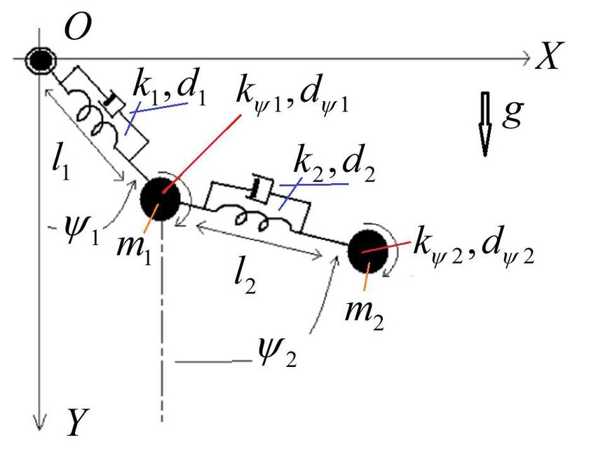
Preprints (www.preprints.org) | NOT PEER-REVIEWED | Posted: 15 September 2021 performance trajectory tracking and high-speed response. Computational efficiency, precision, speed, and accuracy requirements were ensured in the simulation of the whole system. 2. Mathematical Modeling of the Flexible Robot Arm The physical model of the flexible robot arm is represented in Fig.1. Figure 1. Representation of the flexible link robot. The model includes translational and rotational springs and viscous dampers. Lagrangian mechanical principles are utilized to derive the equations of motion (EOM’s) of the whole system. The generalized independent coordinates changing with time are determined as 1(t), 2 (t ), l1(t), l2 (t ) . Large motion and structural variations in the dynamics of the flexible robot arm are investigated in this paper. The kinematic constraints and velocities of the mass centres w.r.t inertial reference frame are stated as in Eq.1 and Eq.2, respectively. 5
Preprints (www.preprints.org) | NOT PEER-REVIEWED | Posted: 15 September 2021 X 1 t l1 t sin 1 t , X 2 t l1 t sin 1 t l2 sin 2 t (1) Y1 t l1 t cos 1 t , Y2 t l1 t cos 1 t l2 t cos 2 t dX 1 sin 1 l1 cos 1 l11 dt dX 2 sin 1 l1 sin 2 l2 cos 1 l11 cos 2 l2 2 dt (2) dY1 sin 1 l11 cos 1 l1 dt dY2 sin 1 l11 sin 2 l2 2 cos 1 l1 cos 2 l2 dt The potential energy that contains the gravitational potential, translational and rotational elastic potential parts, kinetic energy that covers translational and rotational parts, and Rayleigh dissipation function, which highlights the viscous damping loss of the whole system are defined in Eq.3, respectively. 1 1 2 1 1 V m1 gY1 m2 gY2 k1 l1 l10 k2 l2 l20 k 1 1 10 k 2 2 20 2 2 2 2 2 2 2 1 1 1 1 T m1 X 12 Y12 m2 X 22 Y22 J 112 J 2 22 2 2 2 2 1 2 1 2 1 1 R d1l1 d 2l2 d 112 d 2 22 (3) 2 2 2 2 The parameters stated in the Eq.3 refer to the system parameters given in Table 1. Table 1 The system parameters define the flexible robot arm. Definition Notation Gravitational constant Translational spring constants , Translational viscous damping constants , Rotational spring constants , Rotational viscous damping constants , Unloaded length of the links , The unloaded angle of the joints , Translational inertia values , Rotational inertia values , 6
Preprints (www.preprints.org) | NOT PEER-REVIEWED | Posted: 15 September 2021 Four nonlinear second-order differential EOMs are obtained by writing down the Lagrangian equation that describes the dynamics of the flexible robot arm uniquely as in Eq.4, respectively. d L L R d L L R Q1 , Q 2 dt 1 1 1 dt 2 2 2 (4) d L L R d L L R Ql1 , Ql2 dt l1 l1 l1 dt l2 l2 l2 where Lagrangian L T V refers to the difference of the kinetic and potential energy. Qi ’s imply to i th external generalized force corresponds to the generalized source (i.e. mechanical or electrical). The state equations derived from Eq.4 contains the full dynamics of the system. To define the system in state-space form, the 8-dimensional state vector is given in terms of the state variables. These variables are the angular position, angular velocity of the joints, displacement and its derivative of the links, i.e. x1 1 , x2 1 , x3 2 , x4 2 , x5 l1 , x6 l1, x7 l2 , x8 l2 . The state equations can be built by arranging these variables in the form given in Eq.5. X f X , u (5) where X is the state vector, u denotes external input and f (.) is a nonlinear function in a vector form. The state equation in Eq.5 can be re-arranged as in Eq.6. x2 x x1 x2 , x3 x4 , x5 x6 , x7 x8 ; 4 fˆ x1 , x2 , x3 , x4 , x5 , x6 , x7 , x8 , u (6) x6 x8 where fˆ . includes nonlinear terms as state variables and external inputs. After completing the state-space representation, the controller synthesis can be achieved. u 1 The joints are subjected to the external torque vector u u 2 given in Eq.7, rigidly mounted to a 0 0 rotating reference frame. 7
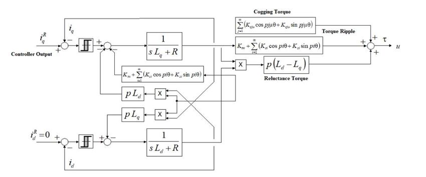
Preprints (www.preprints.org) | NOT PEER-REVIEWED | Posted: 15 September 2021 u1 ktn1 iq1 K1cn cos np11 K1sn sin np11 iq1 K1cj1 cos j 1 1 K1sj1 sin j 1 1 L 1 id 1 iq1 n 1 j 1 n1 j 1 u2 ktn 2 iq 2 K2cn cos np22 K2 sn sin np22 iq 2 K2cj2 cos j 2 2 K2 sj2 sin j 2 2 L 2 id 2 iq 2 (7) where ktn refers to the torque constant (Nm/A), Ld is direct axis stator winding inductance (H), Lq is quadrature axis stator winding inductance (H), L is proportional to − (H), p corresponds to the pole pair number, id and iq indicate the stator currents in terms of direct and quadrature axis components (A), n is the harmonic order (n=1,2,…,∞), K1cn , K2cn , K1sn , K2sn harmonic torque components in terms of cosine and sine coefficients (Nm/A), K1cj1 , K1sj1 , K2cj2 , K2sj2 are cogging torque components in terms of cosine and sine coefficients (Nm). The actuator dynamics can be embedded to complete the full system dynamics with electric motor equations as follows: diq R k b K c n cos np K s n sin np s iq p Ld id n 1 1 v q dt Lq Lq Lq did R 1 s id p Lq iq vd ; vq Vm sign iqr iq k 0,1,2,... ; dt Ld Ld t k Tsw vd Vm sign idr id k 0,1,2,... t k Tsw where Vm is the maximum driver voltage (V), iqr , idr are quadrature and direct axis reference current components of stator current (A), Tsw is the driver switching time constant (sec), vq , vd are quadrature and direct axis components of the stator voltage (V), Rs is the stator phase winding resistance (), kb is the back-emf constant (V.sec/rad), Kcn , Ksn are harmonic flux components (V.sec/rad). Stator voltage components have produced an equivalent driver circuit that is included relay functions with a switching facility. The block diagram, that is utilized in the simulation of the torque input can be represented as in Fig.2. 8
Preprints (www.preprints.org) | NOT PEER-REVIEWED | Posted: 15 September 2021 Figure 2. The block diagram of the torque input having an actuator dynamics model. The generated torques in the joints are constituted by torque ripple, reluctance torque and cogging torque, respectively (The switching of the PWM inverter operation and the torque pulsations in the output torque for the current reference induced by the input-output control law). 3. Controller Framework: Theoretical Remarks and Implementation The control laws were presented in the form of full state feedback. Commonly, the underactuated system control consists of designing a nonlinear observer and developing output feedback stabilization. In real conditions, most actuators are limited in their actuation power. Therefore, the effects of bounded control inputs should also be included in the analysis of nonlinear systems having saturated nonlinear state feedback. The system equations obtained in Eq.6 can be rearranged as in Eq.8. M1 M 2 l1 K1 0 l1 C1 G1 0 0 M m 0 0 g m d u 3 4 1 1 c4 4 4 1 M 4 M 5 l2 K 2 0 l2 C2 G2 0 0 M m d u (8) 6 m7 2 0 0 2 c7 g5 7 2 The uncontrollable variable (d) is stated as a disturbance. The non-collocated output of the system, which approximates the tip position is given in Eq.9. T T M l M l y1 3 1 1 ; y2 6 1 2 (9) m4 1 m7 2 Based on the model above, robust-adaptive linearizing control laws are evaluated as in Eq.10. 1 1 ff 1 W1T Pˆ1 2 2 ff 2 W2T Pˆ 2 iq1 ; iq 2 (10) ktn1 ktn 2 where i ( = 1,2) refer to the tracking control signals, i ( = 1,2) terms correspond to a positive ˆ ( = 1,2) terms represent the deviation from the ideal torque, and contain scaling number, WiT Pi large amplitude and effective torque ripples, cogging torques, respectively. 9
Preprints (www.preprints.org) | NOT PEER-REVIEWED | Posted: 15 September 2021 ~ In addition, it also covers gravity terms, kti kti ktni terms in slow-speed operation, and frictional terms. The regressor vector and related parameter values are given below: WiT 1 cosi sini cos pii sin pii cos2pii sin2pii cos3pii sin3pii cos i i i i sin PiT kˆt gˆ4,5c gˆ4,5s Kˆic1 Kˆis1 Kˆic2 Kˆis2 Kˆic3 Kˆis3 Kˆic Kˆis where is the number of teeth on the stator, kt is the actual value of the torque constant for constant velocity operation. The v ffi ( = 1,2) terms correspond to feedforward terms: ff 1 cˆ4 m4 dˆ and ff 2 cˆ7 m7 dˆ , respectively. At this point, stability analysis is performed by deriving error dynamics. The chattering-free first-order sliding mode control inputs are stated in Eq.11. M3 M 1 e1 1 e1 , e1 1 y1 , e1 1 y1 1 1 y1 1ref 1 3 e1 1ref ref ref ref l1 ; l1 m4 m4 M6 M 2 e2 2 e2 , e2 2 y2 , e2 2 y 2 2 2 y2 2ref 2 6 e2 2ref ref ref ref l2 ; l2 m7 m7 (11) Lyapunov’s stability criteria and the concept of equivalent control is designed based on this sliding 1 2 surface. The Lyapunov function is chosen as: V and V D 2 ; D 0 . 2 1 1 where 1,2 e1,2 Ce1,2 1,2 ref 1,2 P T W 1,2 ; m4,7 m4,7 1 1 If 0 v1,2 eqv,12 , 1,2 m4,7 eqv,12 1,2 , m4,7 eqv,12 1,2 D1,21,2 0 . If one can discretize v1, v2 and their left sides are organised for equivalent control, it can be used the reality that is the equivalent control does not change in one sampling period. m4 1 (k ) 1 (k 1) 1 D1T 1 ( k ) 1 ( k 1) , T m 2 (k ) 2 (k 1) 7 1 D2T 2 (k ) 2 (k 1) T du u ( k ) u ( k 1) d 1,2 m4,7 dt T , 1,2 D1,2 1,2 , dt T m 1,2 4,7 e1,2 C1,2 D1,2 e1,2 C1,2 D1,2 e1,2 dt T 10
Preprints (www.preprints.org) | NOT PEER-REVIEWED | Posted: 15 September 2021 If Eq.8 is re-shaped w.r.t , the equation is transformed into Eq.12. 1 1 M 3 l1 m4 d c4 g 4 u1 m4 1 2 M 6 l2 m7 d c7 g5 u2 m7 1 1 M 3 l1 m4d c4 ktn1iq1 PT W m4 1 2 M 6 l2 m7 d c7 ktn 2iq 2 PT W (12) m7 is defined by other harmonic components that are outside the largest torque harmonics and whose amplitudes are very small. When Eq.7 and Eq.10 is replaced by Eq.12, Eq.13 becomes. 1 1 1 M 3l1 m4d c4 P T W m4 m4 1 1 1 T 1 2 M l m d c P W (13) m7 m7 2 2 6 2 7 7 ~ ˆ where P P P c4,7 cˆ4,7 c4,7 ve d dˆ d A sliding mode controller that is not affected by parameter changes and compensates these error terms is utilized. The error dynamics of the controller that will follow the surface selected as the sliding surface in a chattering free manner, is given in Eq.14. 1 m d c P T W 1 e1 4 4 m 1 1 m4 4 1 1 e2 m d 7 P T W c m7 m7 2 2 7 x1 e1 , x1 x2 , x3 e2 , x3 x4 (14) Eq.14 is stated in state-space form as in Eq.15. x1 0 1 x1 0 x 0 0 x 1 m 1 1 1 P W T 2 2 4 x1 0 1 x3 0 x 0 0 x 1 m 2 2 2 P W T (15) 2 4 7 11
Preprints (www.preprints.org) | NOT PEER-REVIEWED | Posted: 15 September 2021 where 1 m4 d c4 , 2 m7 d c7 Eq.15 is discretized as in Eq.16 to examine the system behaviour on a discrete controller. x1,3 ( k ) 1 T x1,3 (k 1) T T 2 1 1,2 1,2 ( k 1) 1,2 ( k 1) P W T x (k ) (16) 2,4 0 1 x2,4 ( k 1) m4,7 Eq.17 is obtained if the control signal is written in z-domain and put in Eq.16 T 2 ( z 1) 1,2 m4,7 1 D1,2 T z 1 TW E1,2 ( z ) ( z ) ( z ) P (17) 2( z 1)2 m4,7 1,2 1,2 T z 1 where 1 ( z ) 1 T C1 z 1 E ( z) , ( z) 1 T C2 z 1 E ( z) 1 2 2 Tz Tz Eq.17 is arranged as in Eq.18 0 ( z 1) 1 D1 T z 1 1 T C1 z 1 T 2 ( z 1) ( z ) P T W E1 ( z ) 1 2 1 1 2( z 1) z 1 2( z 1) m4 2 z 0 ( z 1) 1 D2 T z 1 1 T C2 z 1 T 2 ( z 1) ( z ) P T W E2 ( z ) 1 2 2 2 (18) 2( z 1) z 1 2( z 1) m7 2 z where T 2 ( z 1) 1,2m4,7 Tz z 1 T E1,2 ( z) ( D1,2 C1,2 ) D1,2C1,2 E1,2 ( z) 1,2 ( z ) P W ; 2( z 1) m4,7 2 T z 1 T z The stability of Eq.18 also requires the right-hand side to be bounded. This condition yields the update law for the parameter adaptation. A stable dynamic can be obtained under the following conditions: 1,2 0, T 0, D1,2C1,2 0, D1,2 C1,2 0, D1,2 C1,2 T 1 1,2 0 Equivalent expression in steady-state can be obtained using the following transformations and equation given in Eq.19. T 2 ( z 1) d2 Tz z 1 d () (); () () dt ; () () 2( z 1) 2 dt 2 z 1 Tz dt 1 m4 1 m4 1 m4 m44 e1 e1 ( D1 C1 ) e1 D1C1 e1 dt 1 P T W T T T 2 m7 2 m7 2 m7 m77 e2 e2 ( D2 C2 ) e2 D2C2 e2 dt 2 P T W (19) T T T 12
Preprints (www.preprints.org) | NOT PEER-REVIEWED | Posted: 15 September 2021 If 1 e1 dt and 2 e2 dt are defined and replaced into Eq.19, Eq.20 is obtained. 1 m4 1 m4 1 m4 m4 1 1 ( D1 C1 ) 1 D1 C1 1 1 P T W T T T 2 m7 2 m7 2 m7 m7 2 2 ( D2 C2 ) 2 D2 C2 2 2 P T W (20) T T T The Lyapunov stability criterion is applied in Eq.21 under the condition that 1 0 and 2 0 are too small. 1 1 1 1 1,2 1 1,2 2 1,2 3 1,2 2 V 2 4 1,2 2 P T Γ 1P 2 2 2 2 V 1,2 1 1,2 2 1,2 1,2 1 1,2 2 1,2 3 1,2 1,2 4 1,2 1,2 P T Γ 1P (21) where 1, 2, 3, 4 0 are coefficients, and is a strictly positive matrix. Lyapunov function’s derivative w.r.t time should be negative for stability. The equations and inequalities, that make the Lyapunov function’s derivative w.r.t time negative is stated in Eq.22. 2 2 1,2 V 1 1,2 1,2 1 2 1,2 D1,2 C1,2 1 1,2 2 D1,2 C1,2 1,2 2 4 2 12 1,2 D1,2 C1,2 1,2 1 1,2 1,2 T T T T T 1,2 1,2 1 2 D1,2C1,2 2 1,2 1,2 T T W 3 22 1,2 D1,2 C1,2 2 1,2 1D1,2C1,2 1,2 1,2 P T Γ1P 1,2 1 1,2 2 1,2 0 T T m44,77 1,2 1,2 1,2 1 T ; T 2 D1,2 C1,2 1,2 2 0 ; 1 2 T D1,2 C1,2 1 0 2 1,2 D1,2 C1,2 T 1,2 1,2 4 2 1 T D1,2 C1,2 T 1 0 4 = 0 2 1,2 1,2 1,2 1 2 T D1,2C1,2 T 2 0 D1,2C1,2 0 T 1,2 1,2 2 3 2 2 T D1,2 C1,2 2 T 1D1,2C1,2 0 3 1,22 D1,2C1,2 T P T Γ 1P W 1,2 1 1,2 2 1,2 0 P~T 0 , P Γ W 1,2 1 1,2 2 1,2 m4,7 m4,7 (22) where 1,2 , D1,2 , C1,2 , T 0 13
Preprints (www.preprints.org) | NOT PEER-REVIEWED | Posted: 15 September 2021 The error goes to zero when the parameter errors go to zero under the assumption that the parameters change slowly. The parameter update law is as follows: 1,2 1,2 1,2 T 1,2 T D1,2 C1,2 1,2 P Pˆ Γ W m4,7 The fulfilment of these conditions ensures that the error dynamics converge to zero exponentially. The persistency of excitation of the regressor is proven in [Mareels&Gevers, 1988] for nonzero velocity; therefore, parameter convergence is guaranteed. With the stability analysis of the active DOF under the designed control performed as above, the stability of the output zero dynamics should also be analyzed using the equations of the passive DOF’s. Zero dynamics are obtained as the output is taken zero “ = 0”. In this condition, Eq.8 becomes as in Eq.23. 1,2 K1,2 q1,2 C1,2 G1,2 0 M1,2 q (23) 2 l1,2 M 2,5 M 3,6 M where q1,2 ; M1,2 M 1,4 ; C1,2 M 2,5 q1,2 3,6 q1,2 1 ; G1,2 G1,2 cos1,2 m 1,2 m4,7 4,7 M 3,6 and G is a vector consisting of constant coefficients and 1,2 q1,2 . m4,7 To examine the stability of this system, one can say that M and K are positive-definite. In this case, system stability can be investigated under a Lyapunov function to be chosen as in Eq.24. 1 T 1 T V q 1,2 M1,2 q 1,2 q1,2 K1,2 q1,2 2 2 (24) V q 1,2 T M1,2 q1,2 K1,2 q1,2 q 1,2T G1,2 cos1,2 0 To find the conditions V0 : M 3,6 M 3,6 d M G M 1,2 q1,2 , yielding q 1,2 T G1,2 cos q1,2 m44,77 3,6 1,2 sin 3,6 q1,2 0 m4,7 m4,7 dt M 3,6 M 2,5 m4,7 1,2 0 M 3,6G1,2 M 3,6 Therefore, if A is a scalar constant value, it can be written as: m4,7 sin q1,2 A . M 3,6M 2,5 m4,7 0 1,2 and sin 1,2 1 , the boundedness criteria is assured. In this case, one can say that 2 V 0 and the zero dynamics are stable. 14
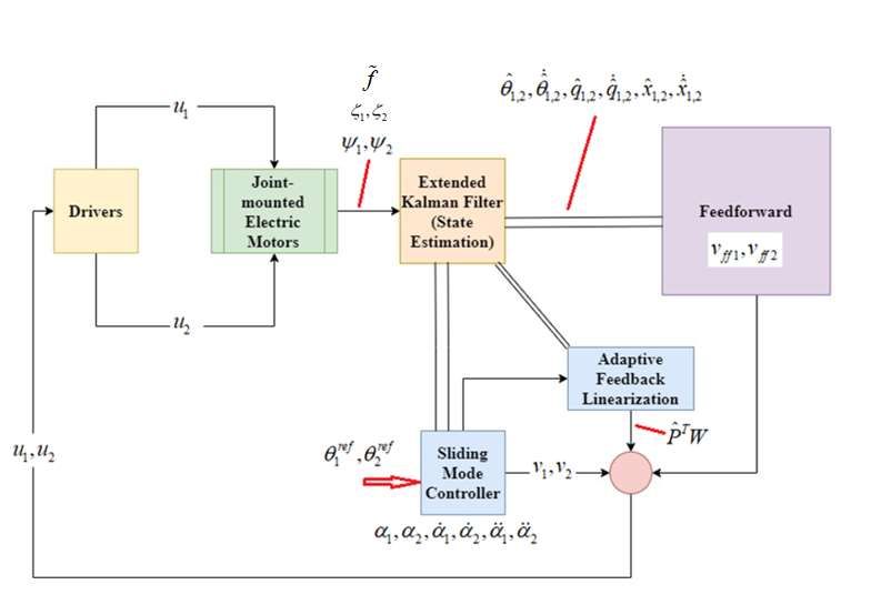
Preprints (www.preprints.org) | NOT PEER-REVIEWED | Posted: 15 September 2021 The general block diagram of the proposed control system is demonstrated in Fig.3. Figure 3. General block diagram of the proposed control system. Extended Kalman Filter (EKF) was designed in the simulation for the estimation of immeasurable variables and parameters required for the control algorithms. Estimation was performed based on rotation angles ( 1, 2 ), strains ( 1 , 2 ) and force disturbance ( f ) measurements. 4. Simulation Results The simulation results of the designed robust-adaptive linearizing controller will be presented. The simulation was conducted in Matlab/Simulink with an ode4 (Runge-Kutta) solver and 1e-3 fixed step size. The manipulator is constructed from two flexible links connected by a rigid joint. The joint actuators were selected as a permanent-magnet synchronous motor (PMSM). Simulation performed for control methods were evaluated under the same disturbance effect, which is reflected in the system by the displacement of the moving mass. To demonstrate the performance improvement achieved with its compensations for both set-point and tracking control, the case with no compensation was also presented. Simulations were conducted for both step-type and sinusoidal-type end-point references to show the control scheme performances for both set point and tracking control while subjected to a periodic disturbance having pulse characteristic (presented in Fig.4&Fig.5). 15
Preprints (www.preprints.org) | NOT PEER-REVIEWED | Posted: 15 September 2021

 a)

 b)

 c)
 q2

 16
Preprints (www.preprints.org) | NOT PEER-REVIEWED | Posted: 15 September 2021

 d)

 Figure 4. Disturbance on the flexible robot arm, which is reflected as the displacement of the moving
 mass (4a). Set-point (4b-4c) and tracking (4d) control performance of the SMC-based adaptive
 linearizing control scheme concerning the step type endpoint reference (the units are in meter).

 a)
 Reference Tracking Signal (Tip) [rad]

 b)

 17
Preprints (www.preprints.org) | NOT PEER-REVIEWED | Posted: 15 September 2021

 c)

 q2

 d)
 Amplitude

 Figure 5. A sinusoidal reference signal for tracking control (5a). Set-point (5b-5c) and tracking (5d)
 control performance of the SMC-based adaptive linearizing control scheme concerning the sinusoidal
 type endpoint reference (the units are in radian).

 Inspection of the results demonstrates the significant improvement made with the robust adaptive
 linearization-based chattering-free SMC for set-point and tracking control, in terms of both transient
 and steady-state precision.

 The error variations of the calculated speed and position would be sufficient and more consistent
 with the rest of the results. It should be captured and inferred from figures that all transitions can
 ensure a smooth transition of motor currents without any significant impact ensuring the smooth
 transition of the torque and operational stability. The smooth transition mechanism existing in the
 literature i.e, CHMPWM, SHEPWM, Hybrid Synchronized PWM, SVPWM etc. can also be considered
 for further investigation. Because of the flexibility of the link, rotating the base of the link causes the
 entire link to oscillate. The control problem is to move the tip of the link to the desired setpoint by
 applying a control input at the base of the link. This is a classic example of non-collocated control; i.e.
 the actuator is located away from the point it is controlling (the tip). Classic control methodologies
 such as PD and PID strategies can only be used to control the motor position. These control

 18
Preprints (www.preprints.org) | NOT PEER-REVIEWED | Posted: 15 September 2021

 techniques essentially ignore the flexibility of the link, and hence the position response exhibits
 lightly damped oscillatory behaviour. To quickly and effectively remove the vibrations from the
 system, it is necessary to incorporate the position of the tip into the control scheme. Several such
 control strategies (i.e., bounded input discrete-time H-2 control, H-infinity control, passive control,
 fuzzy control, Closed-loop shaped-input control) have been successfully implemented on the link
 (i.e.[Lin&Varaiya, 1967; Krishnan&Vidyasagar, 1988; Karkoub&Tamma, 2001; Altıner et.al., 2018;
 Wang&Vidyasagar, 1992; Kuo&Lin, 2002; Zuo et.al, 1995]. These control strategies will not provide
 adequate performance if the payload mass is varied.

 5. Conclusive Summary and Discussion
 The implementation of SMC based on chattering-free control input, for which realistic applications
 are rather rare, was done in this paper. To exploit the well-known robustness properties of SMC
 concerning internal and external disturbances, while also improving accuracy and eliminating the
 unwanted chattering effects, a robust-adaptive linearization control scheme combining continuous
 SMC, was proposed. As an underactuated system with heavy uncertainties, a flexible robot arm was
 modelled and simulated for designing a high precision control system. Structural flexibilities, a high
 number of passive DOF arising from a variety of operation modes, gravitational effects were taken
 into consideration while concerning high-speed operation and accuracy. Actuator dynamics with
 inverter switching effects, current dynamics and torque pulsations were also investigated due to the
 high-performance controller demands that handle modelling errors arising from parameter and
 model uncertainties, and sources that could excite unmodeled dynamics. Besides, zero dynamic
 stability was analyzed. The deteriorating effects of torque pulsations on system performance and the
 improved performance achieved with their compensations were also demonstrated. The results
 taken under disturbances simulated via pulse functions demonstrate significant improvements in
 terms of trajectory tracking control and set-point control. This paper also presents an in-depth
 analysis of finite-time convergence, stability and robustness issues for the application of SMC to
 systems with heavy uncertainties. The conventional application with discontinuous input was also
 modified with the inclusion of the actuator dynamics. The developed method appears to have
 significant value in terms of increasing practical applications in nonlinear flexible robot
 dynamics&control. The equivalent circuit model and dynamic model of the PMSM motor was utilized
 to understand the current and torque shock generation mechanism. A specific scheme was
 constructed to see the smooth transition in hybrid PWM among various modulation modes in the full
 speed range by proving the feasibility and correctness of the scheme experimentally. The extent
 dynamics and disturbances (i.e. harmonic distortion, harmonic spectrum) considered in the
 simulations appear satisfactory for performance evaluation. The drawback of this paper is the lack of
 experimental results, but the system and the extent of dynamics and disturbances consider in the
 simulations appear satisfactory for performance evaluation. The main difference from the literature
 is that in this paper, the internal dynamics of the regressor (for the torque pulsations, gravitational,
 and friction torque) has been proven to be persistently exciting for nonzero velocity; thus, for online
 adaptation of parameters, particularly for set-point tracking, the problem of parameter drift was also
 be taken into consideration. Stability analysis of the zero dynamics arising from the passive DOFs was
 performed for each controller and the system output.

 Conflicts of Interest
 The authors declare that there are no conflicts of interest.

 19
Preprints (www.preprints.org) | NOT PEER-REVIEWED | Posted: 15 September 2021

 References
 Aghili, F., Buehler, M., & Hollerbach, J. (1997). Dynamics and control of direct-drive robots with
 positive joint torque feedback. Proceedings of International Conference on Robotics and Automation.

 Aghili, F., Buehler, M., & Hollerbach, J. (1998). Torque ripple minimization in direct-drive
 systems. Proceedings. 1998 IEEE/RSJ International Conference on Intelligent Robots and Systems.
 Innovations in Theory, Practice and Applications (Cat. No.98CH36190).

 Alandoli, E. A., & Lee, T. S. (2020). A Critical Review of Control Techniques for Flexible and Rigid Link
 Manipulators. Robotica, 38(12), 2239-2265.

 Ali, H. I., & Abdulridha, A. J. (2020). H-infinity Sliding Mode Controller Design for a Human Swing Leg
 System. Al-Nahrain Journal for Engineering Sciences, 23(2), 117-126.

 Almakhles, D. J. (2020). Robust Backstepping Sliding Mode Control for a Quadrotor Trajectory
 Tracking Application. IEEE Access, 8, 5515-5525.

 Altıner, B., Delibaşı, A., & Erol, B. (2018). Modeling and control of flexible link manipulators for
 unmodeled dynamics effect. Proceedings of the Institution of Mechanical Engineers, Part I: Journal of
 Systems and Control Engineering, 233(3), 245-263. doi:10.1177/0959651818791071

 Ansarieshlaghi, F., & Eberhard, P. (2018). Experimental study on a nonlinear observer application for
 a very flexible parallel robot. International Journal of Dynamics and Control, 7(3), 1046-1055.

 Arısoy, A., Gokasan, M., Bogosyan, O. (2010). Esnek-mafsallı robot kolun yüksek dereceli kayma kipli
 kontrolü. İTÜ Dergisi/d, Cilt 9, Sayı 1.

 Arisoy, A., Gokasan, M., & Bogosyan, O. (2005). Partial feedback linearization control of a single
 flexible link robot manipulator. Proceedings of 2nd International Conference on Recent Advances in
 Space Technologies, 2005. RAST 2005.

 Arteaga, M., & Siciliano, B. (2000). On tracking control of flexible robot arms. IEEE Transactions on
 Automatic Control, 45(3), 520-527.

 Ayten, K. K., & Dumlu, A. (2018). Real-Time Implementation of Sliding Mode Control Technique for
 Two-DOF Industrial Robotic Arm. Journal of the Institute of Science and Technology, 77-85.

 Azizi, Y., & Yazdizadeh, A. (2019). Passivity-based adaptive control of a 2-DOF serial robot
 manipulator with temperature dependent joint frictions. International Journal of Adaptive Control
 and Signal Processing, 33(3), 512-526.

 Bergerman, M., Lee, C., & Xu, Y. (1995). Experimental study of an underactuated manipulator.
 Pittsburgh, PA: Carnegie Mellon University, the Robotics Institute.

 Cambera, J. C., & Feliu-Batlle, V. (2017). Input-state feedback linearization control of a single-link
 flexible robot arm moving under gravity and joint friction. Robotics and Autonomous Systems, 88, 24-
 36.

 Chang, Y., Chen, B., & Lee, T. (1996). Tracking control of flexible joint manipulators using only
 position measurements. International Journal of Control, 64(4), 567-593.

 Cheah, C., Liu, C., & Slotine, J. (2006). Adaptive Jacobian Tracking Control of Robots With
 Uncertainties in Kinematic, Dynamic and Actuator Models. IEEE Transactions on Automatic
 Control, 51(6), 1024-1029.

 20
Preprints (www.preprints.org) | NOT PEER-REVIEWED | Posted: 15 September 2021

 Chen, H., & Sun, N. (2020). Nonlinear Control of Underactuated Systems Subject to Both Actuated
 and Unactuated State Constraints With Experimental Verification. IEEE Transactions on Industrial
 Electronics, 67(9), 7702-7714.

 Din, S. U., Khan, Q., Rehman, F. U., & Akmeliawati, R. (2016). Robust Control of Underactuated
 Systems: Higher Order Integral Sliding Mode Approach. Mathematical Problems in Engineering, 2016,
 1-11.

 Farahmandrad, M., Ganjefar, S., Talebi, H. A., & Bayati, M. (2019). Design of higher-order sliding
 mode controller based on genetic algorithm for a cooperative robotic system. International Journal
 of Dynamics and Control, 8(1), 269-277.

 Fei, Q., Deng, Y., Li, H., Liu, J., & Shao, M. (2019). Speed Ripple Minimization of Permanent Magnet
 Synchronous Motor Based on Model Predictive and Iterative Learning Controls. IEEE Access, 7,
 31791-31800.

 Fei, W., & Luk, P. C. (2009). A new technique of cogging torque suppression in direct-drive permanent
 magnet brushless machines. 2009 IEEE International Electric Machines and Drives Conference.

 Gokasan, M., Bogosyan, O., Sabanovic, A., & Arabyan, A. (1998). A sliding mode observer and
 controller for a single link flexible arm. Proceedings of the 37th IEEE Conference on Decision and
 Control (Cat. No.98CH36171).

 Guo, W., & Liu, D. (2014). Nonlinear Recursive Design for the Underactuated IWP System. Journal of
 Applied Research and Technology, 12(3), 602-606.

 Han, J., Yang, S., Xia, L., & Chen, Y. (2020). A Novel Trajectory Tracking Control Strategy for
 Underactuated Quadrotor UAV with Uncertainties and Disturbances.

 Han, L., Chen, M., Wu, Q., & Li, X. (2016). Sliding mode control using disturbance observer for a
 flexible link robot. 2016 14th International Workshop on Variable Structure Systems (VSS).

 Hosaka, M., & Murakami, T. (2006). Vibration control of flexible arm by multiple observer
 structure. Electrical Engineering in Japan, 154(2), 68-75.

 Jiang, L., Gao, B., & Zhu, Z. (2017). Design and Nonlinear Control of a 2-DOF Flexible Parallel
 Humanoid Arm Joint Robot. Shock and Vibration, 2017, 1-14.

 Jin, Q., Liu, Q., Wang, Q., Li, S., & Wang, Z. (2013). IMC-PID Design: Analytical Optimization for
 Performance/Robustness Tradeoff Tuning for Servo/Regulation Mode. Asian Journal of
 Control, 16(4), 1252-1261.

 Karkoub, M., & Tamma, K. (2001). Modelling and μ-synthesis control of flexible
 manipulators. Computers & Structures, 79(5), 543-551. doi:10.1016/s0045-7949(00)00155-3

 Kostic, D., Jager, B. D., & Steinbuch, M. (2002). Robust attenuation of direct-drive robot-tip
 vibrations. IEEE/RSJ International Conference on Intelligent Robots and System.

 Krafes, S., Chalh, Z., & Saka, A. (2018). A Review on the Control of Second Order Underactuated
 Mechanical Systems. Complexity, 2018, 1-17.

 Krener, A. J. (2015). Differential Geometric Methods in Nonlinear Control. Encyclopedia of Systems
 and Control, 275-284.

 21
Preprints (www.preprints.org) | NOT PEER-REVIEWED | Posted: 15 September 2021

 Krishnan, H., & Vidyasagar, M. (1988). Bounded input feedback control of linear systems with
 application to the control of a flexible system. Proceedings of the 27th IEEE Conference on Decision
 and Control. doi:10.1109/cdc.1988.194601

 Kuo, K., & Lin, J. (2002). Fuzzy logic control for flexible link robot arm by singular perturbation
 approach. Applied Soft Computing, 2(1), 24-38. doi:10.1016/s1568-4946(02)00026-1

 Lai, X., Xiong, P., & Wu, M. (2019). Stable control strategy for a second-order nonholonomic planar
 underactuated mechanical system. International Journal of Systems Science, 50(11), 2126-2141.

 Li, Y., Tong, S., & Li, T. (2013). Adaptive fuzzy output feedback control for a single-link flexible robot
 manipulator driven DC motor via backstepping. Nonlinear Analysis: Real World Applications, 14(1),
 483-494.

 Lin, J., & Varaiya, P. (1967). Bounded-input bounded-output stability of nonlinear time-varying
 discrete control systems. IEEE Transactions on Automatic Control, 12(4), 423-427.
 doi:10.1109/tac.1967.1098631

 Liu, H., Huang, Y., & Wu, W. (2016). Improved adaptive output feedback controller for flexible-joint
 robot manipulators. 2016 IEEE International Conference on Information and Automation (ICIA).

 Liu, L., & Yuan, K. (2003). Noncollocated passivity-based PD control of a single-link flexible
 manipulator. Robotica, 21(2), 117-135.

 Lochan, K., Roy, B., & Subudhi, B. (2016). SMC Controlled Chaotic Trajectory Tracking of Two-Link
 Flexible Manipulator with PID Sliding Surface. IFAC-PapersOnLine, 49(1), 219-224.

 Loria, A., & Avila-Becerril, S. (2014). Output-feedback global tracking control of robot manipulators
 with flexible joints. 2014 American Control Conference.

 Luca, A. D., Lanari, L., & Ulivi, G. (1991). Nonlinear Regulation of End-Effector Motion for a Flexible
 Robot Arm. New Trends in Systems Theory, 229-236.

 Mansor, N. N., Jamaluddin, M. H., Shukor, A. Z., & Lok, C. C. (2018). A Study of Accuracy and Time
 Delay for Bilateral Master-Slave Industrial Robotic Arm Manipulator System. MATEC Web of
 Conferences, 150, 01015.

 Mareels, I. M., & Gevers, M. (1988). Persistency of excitation criteria for linear, multivariable, time-
 varying systems. Mathematics of Control, Signals, and Systems, 1(3), 203-226.

 Markus, E. D. (2015). Flatness based Feed-forward Control of a Flexible Robot Arm under Gravity and
 Joint Friction. Proceedings of the 12th International Conference on Informatics in Control,
 Automation and Robotics.

 Martínez, S., Cortés, J., & Bullo, F. (2003). Motion Planning and Control Problems for Underactuated
 Robots. Control Problems in Robotics Springer Tracts in Advanced Robotics, 59-74.

 Matsui, N. (1993). Autonomous torque ripple compensation of DD motor by torque
 observer. Proceedings 1993 Asia-Pacific Workshop on Advances in Motion Control.

 Mattioni, A., Wu, Y., & Gorrec, Y. L. (2020). Infinite dimensional model of a double flexible-link
 manipulator: The Port-Hamiltonian approach. Applied Mathematical Modelling, 83, 59-75.

 22
Preprints (www.preprints.org) | NOT PEER-REVIEWED | Posted: 15 September 2021

 Meurer, T., Thull, D., & Kugi, A. (2008). Flatness-based tracking control of a piezoactuated Euler–
 Bernoulli beam with non-collocated output feedback: Theory and experiments†. International
 Journal of Control, 81(3), 475-493.

 Montazeri, A., Poshtan, J., & Choobdar, A. (2009). Performance and robust stability trade-off in
 minimax LQG control of vibrations in flexible structures. Engineering Structures, 31(10), 2407-2413.

 Mujumdar, A., Kurode, S., & Tamhane, B. (2014). Control Of Two Link Flexible Manipulator Using
 Higher Order Sliding Modes and Disturbance Estimation. IFAC Proceedings Volumes, 47(1), 95-102.

 Naayagi, R., & Kamaraj, V. (2005). Minimization of torque ripple in switched reluctance machine for
 direct drive applications. Proceedings of the IEEE Symposium on Emerging Technologies, 2005.

 Ovalle, L., Rios, H., & Llama, M. (2019). Continuous Sliding-Mode Control for a Class of Underactuated
 Systems. 2019 IEEE 58th Conference on Decision and Control (CDC).

 Pandya, S. N., & Chatterjee, J. K. (2010). Torque ripple minimization in direct torque control based
 induction motor drive using optimal multirate sampling technique. 2010 Joint International
 Conference on Power Electronics, Drives and Energy Systems & 2010 Power India.

 Park, J., Chang, P., Park, H., & Lee, E. (2006). Design of learning input shaping technique for residual
 vibration suppression in an industrial robot. IEEE/ASME Transactions on Mechatronics, 11(1), 55-65.

 Petridis, A. G., & Kanarachos, A. E. (2007). Response optimization of a nonlinear controlled flexible
 robot arm carrying a variable mass. Progress in System and Robot Analysis and Control Design
 Lecture Notes in Control and Information Sciences, 465-476.

 Petrovic, V., Ortega, R., Stankovic, A., & Tadmor, G. (1998). An adaptive controller for minimization of
 torque ripple in PM synchronous motors. PESC 98 Record. 29th Annual IEEE Power Electronics
 Specialists Conference (Cat. No.98CH36196).

 Petrovic, V., Ortega, R., Stankovic, A., & Tadmor, G. (2000). Design and implementation of an
 adaptive controller for torque ripple minimization in PM synchronous motors. IEEE Transactions on
 Power Electronics, 15(5), 871-880.

 Rudra, S., Barai, R. K., & Maitra, M. (2016). Challenges and New Frontiers in the Field of
 Underactuated Mechanical Systems Control. Block Backstepping Design of Nonlinear State Feedback
 Control Law for Underactuated Mechanical Systems, 145-153.

 Santibanez, V., Kelly, R., & Llama, M. (2005). A novel global asymptotic stable set-point fuzzy
 controller with bounded torques for robot manipulators. IEEE Transactions on Fuzzy Systems, 13(3),
 362-372.

 Sayahkarajy, M., Mohamed, Z., & Faudzi, A. A. (2016). Review of modelling and control of flexible-link
 manipulators. Proceedings of the Institution of Mechanical Engineers, Part I: Journal of Systems and
 Control Engineering, 230(8), 861-873.

 Sinha, A., & Mishra, R. K. (2013). Smooth sliding mode controller design for robotic arm. 2013
 International Conference on Control, Automation, Robotics and Embedded Systems (CARE).

 Souza, A. G., & Souza, L. C. (2016). H Infinity Attitude Controller Design for a Rigid-Flexible Satellite
 Considering the Parametric Uncertainty. SAE Technical Paper Series.

 23
Preprints (www.preprints.org) | NOT PEER-REVIEWED | Posted: 15 September 2021

 Şahin, A., & Öner, Y. (2021). High Efficient Permanent Magnet Synchronous Motor Design,
 Electromagnetic and Noise-Vibration Analyzes. Balkan Journal of Electrical and Computer
 Engineering.

 Toussaint, G., Basar, T., & Bullo, F. (2001). Motion planning for nonlinear underactuated vehicles
 using H∞ techniques. Proceedings of the 2001 American Control Conference. (Cat. No.01CH37148).

 Tuan, L. A., & Lee, S. (2016). Nonlinear Feedback Control of Underactuated Mechanical
 Systems. Nonlinear Systems - Design, Analysis, Estimation and Control.

 Uecker, D., Wang, Y., & Kokkinis, T. (1991). Experimental evaluation of real-time model-based control
 of a 3-DOF closed-chain direct-drive mechanism. Proceedings. 1991 IEEE International Conference on
 Robotics and Automation.

 Ullah, M. I., Ajwad, S. A., Irfan, M., & Iqbal, J. (2016). MPC and H-Infinity Based Feedback Control of
 Non-Linear Robotic Manipulator. 2016 International Conference on Frontiers of Information
 Technology (FIT).

 Wang, D., & Vidyasagar, M. (1992). Passive Control of a Stiff Flexible Link. The International Journal of
 Robotics Research, 11(6), 572-578. doi:10.1177/027836499201100606

 Xin, X., & Yamasaki, T. (2012). Energy-Based Swing-Up Control for a Remotely Driven Acrobot:
 Theoretical and Experimental Results. IEEE Transactions on Control Systems Technology, 20(4), 1048-
 1056.

 Xu, R., & Özgüner, Ü. (2008). Sliding mode control of a class of underactuated
 systems. Automatica, 44(1), 233-241.

 Yang, J. H., Lian, F. L., & Fu, L. C. (1997). Nonlinear adaptive control for flexible-link manipulators. IEEE
 Transactions on Robotics and Automation, 13(1), 140-148.

 Yu, Z., Chen, H., & Woo, P. (2003). Polytopic gain scheduled H ∞ control for robotic
 manipulators. Robotica, 21(5), 495-504.

 Zhou, B., Yang, L., Wang, C., Chen, Y., & Chen, K. (2020). Inverse Jacobian Adaptive Tracking Control
 of Robot Manipulators with Kinematic, Dynamic, and Actuator Uncertainties. Complexity, 2020, 1-12.

 Zuo, K., Drapeau, V., & Wang, D. (1995). Closed Loop Shaped-Input Strategies for Flexible Robots. The
 International Journal of Robotics Research, 14(5), 510-529. doi:10.1177/027836499501400507

 24
You can also read