Determining the parameters of the trajectory of the bucket of mining quarries excavators
←
→
Page content transcription
If your browser does not render page correctly, please read the page content below

E3S Web of Conferences 280, 05013 (2021)                                                                https://doi.org/10.1051/e3sconf/202128005013
ICSF 2021

       Determining the parameters of the trajectory of the bucket of
       mining quarries excavators
       Valerii Tytiuk1,*, Kamal Khandakji2, Galina Sivyakova3, Nadezhda Karabut1, Oleksii Chornyi4, and Victor Busher5
       1Kryvyi Rih National University, 11 Vitalii Matusevych Str., Kryvyi Rih, 50027, Ukraine
       2TafilaTechnical University, Department of Electrical Power and Mechatronics Engineering, Jordan
       3Karaganda State Industrial University, Department of Power Industry and Automation of Technical Systems, Kazakhstan
       4Kremenchuk Mykhailo Ostrohradskyi National University, Institute of Electromechanics, Energy Saving and Automatic Control

       Systems, 20 Pershotravneva Str., Kremenchuk, 39600, Ukraine
       5National University Odessa Maritime Academy, Department of Electrical Engineering and Electronics, 8 Didrikhsona Str., Odessa,

       65000, Ukraine

                     Abstract. The bucket positioning of the excavator in three-dimensions (3-D) is the precondition of the
                     robotic excavator starting automatized works. The electric excavator is one of the most widely used
                     machinery in the mining industry, mainly due to its versatility and portability. Among the tasks performed
                     by the excavator, there is a significant number of repetitive movements associated with moving the bucket
                     to the unloading point and back to the face. Using automated functions to perform such repetitive tasks will
                     not only significantly increase overall productivity, but also reduce energy consumption. This research is
                     carried out to create a method of coordinate control of electric drives of the boom, dipper stick, and bucket
                     of an electric excavator to perform accurate and efficient work. On the basis of the kinematic analysis of the
                     excavator's attachment system, the trajectory of the end of the working body can be determined from the
                     point of view of the coordinated movement of the electric drives of the main mechanisms of the excavator.
                     Thus, the complex algorithm of the excavator bucket 3-D position control can be carried out by coordinated
                     control of the movement of three separate electric drives. This coordinate control algorithm was tested on
                     the example of the EKG-8I excavator, and the results of the verification showed that this developed control
                     method can satisfactorily perform the function of automatic control of the bucket position in three-
                     dimensional space. Optimization of control will be further carried out based on the analysis of the energy
                     efficiency of various possible trajectories.

                                                                                     In the mining industry, the production of new
       1 Introduction                                                           generation equipment is characterized by a functional
                                                                                and constructive combination of electromechanical
       The excavator is an earth-moving machine designed for                    converters with energy and information components with
       excavation of soil with lifting, moving it and unloading it              a high level of organization of control processes, i.e., the
       into a dump or onto vehicles. Excavators play an                         creation of mechatronic complexes. A modern excavator
       important role in opencast mining of ore deposits, are                   is a complex of interconnected electrical, mechanical,
       used in land reclamation and road construction, dredging                 electromechanical and electronic systems of high
       and port work, and the building of defensive                             complexity [1]. This allows us to consider the
       constructions.                                                           technological units of the excavator as mechatronic
           The most powerful excavators are used in open pit                    modules, combined into a complex mechatronic complex
       mining both for stripping operations and for reloading the               [2].
       rock mass and forming dumps. Discontinuous single-                            For mechatronic complexes of mining machines, due
       bucket excavators are most widely used in these                          to their significant installed capacity, the energy
       production conditions. Discontinuous (cyclic) excavators                 efficiency of their functioning is of great importance.
       perform work operations in a specific sequence, forming                  Increasing the efficiency of using electrical energy in
       a full working cycle; the movement of the machine itself                 industry and, consequently, mechatronic systems of
       is carried out after performing several cycles.                          mining machines is a determining factor in the
           They are made with various types of interchangeable                  development of technical systems in the near future [3].
       working equipment (Fig. 1), but in any case, the working                      In this regard, the study and modeling of energy
       body has rigid connections with the machine                              processes is of decisive importance in the design of
       mechanisms, which limits its degrees of freedom.                         mechatronic systems for mining machines.

       *   Corresponding author: tytiuk@knu.edu.ua

  © The Authors, published by EDP Sciences. This is an open access article distributed under the terms of the Creative Commons Attribution License 4.0
  (http://creativecommons.org/licenses/by/4.0/).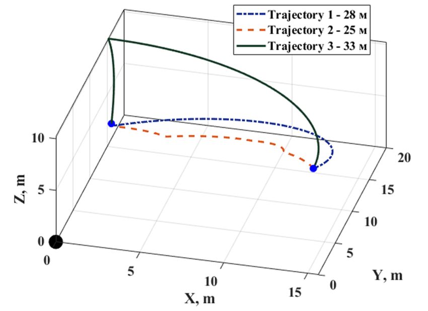
E3S Web of Conferences 280, 05013 (2021)                                                             https://doi.org/10.1051/e3sconf/202128005013
ICSF 2021

       Fig. 1 The main types of single-bucket excavators: a) a power shovel; b) a backhoe; c) a dragline.

                                                                              electric drives for lifting and head during the digging
                                                                              process is considered in articles [12, 13], but the
       2 Literature review                                                    operation of the same mechanisms in other sections of the
       At present, this task is becoming extremely urgent due to              trajectory is not considered.
       the fundamental renewal of both the power equipment of                     Thus, there is a contradiction between the practical
       the excavator electric drives and the technical means of               need to increase the energy efficiency of industrial
       control. Energy calculation remains the most difficult and             mechatronic systems, on the one hand, and the limited
       critical stage in the design of mechatronic systems. At                capabilities of modern methods of analysis and synthesis
       present, it is carried out using separate methods [4],                 and control algorithms for solving this problem. An
       which do not take into account the settings of regulating              important distinguishing feature of mechatronic devices
       devices and the features of power converters.                          is the presence of a perfect system for monitoring and
           Analysis of modern scientific and technical literature             controlling the position of the working bodies [14]. But
       indicates that at present there is no general theoretical              it should be noted that the modern equipment of mining
       approach to the analysis and synthesis of control systems              excavators does not contain a system for controlling the
       that ensure the rational use of electricity in mechatronic             position of the working body. These functions are
       systems, and effective models of energy processes for the              performed by the excavator operator by the joint or
       study and design of mechatronic systems. Modern                        separate movement of individual elements of the
       methods of designing mechatronic systems make it                       kinematic chain with visual control of the result, which
       possible to synthesize the structure with a given quality              significantly reduces the possibility of automatic
       of transient processes [5, 7]. Standard methods for                    optimization of productivity, energy consumption,
       adjusting the regulators of slave circuits of electric drive           increases the requirements for the operator's
       systems – modular and symmetric optima [6, 7], do not                  qualifications.
       take into account not only energy losses and the influence                 The solution to this problem is possible only with the
       of power supplies, but also the different physical essence             correct formulation of a complex of interrelated scientific
       of control processes in a mechatronic system. For electric             and practical problems: the formation of indicators of the
       drive systems with thyristor and transistor energy                     energy efficiency of mechatronic systems of mining
       converters, the operation of which is characterized by                 machines, taking into account both energy costs and
       harmonic distortions of the shape of currents and                      changes in productivity when implementing various
       voltages, both calculations and measurements of energy                 control laws; automating the development of optimal
       characteristics turn out to be difficult, since specialized            trajectories for moving the working bodies of
       measuring instruments for these purposes are not                       mechatronic systems in space; implementation of high-
       produced, and models and estimates of the parameters of                quality positional control systems that ensure the
       electric power processes for nonlinear systems do not                  development of these trajectories; verification of the
       have unambiguous and generally accepted definitions [8,                obtained technical solutions and their approbation in
       9]. The synthesis of control systems that are optimal in               industry.
       terms of the minimum energy consumption is a complex                       The formulated range of tasks cannot be considered
       problem, which in many cases does not have an                          in detail within one publication. The aim of this work is
       unambiguous solution [10]. In addition, as shown in [11],              to develop a mathematical model of the mechanical part
       the minimum energy consumption is not identical to the                 of open-pit excavators, which provides a solution to the
       increase in the energy efficiency of technical systems.                inverse kinematics problem, i.e. establishing the required
           The synthesis of control systems optimal in terms of               law of motion of individual mechanisms of a mining
       energy efficiency is significantly hampered by the lack of             excavator to ensure a given trajectory of movement of the
       scientific papers devoted to a comprehensive analysis of               working body, which will further determine and optimize
       the interrelated movements of excavator mechanisms to                  energy and technical and economic indicators when
       implement the desired trajectories of the bucket                       performing a working cycle.
       movement during the working cycle. A significant part
       of well-known scientific works is devoted to the study of
       individual excavator mechanisms, isolated from the
       general complex. The interconnected operation of the

                                                                         2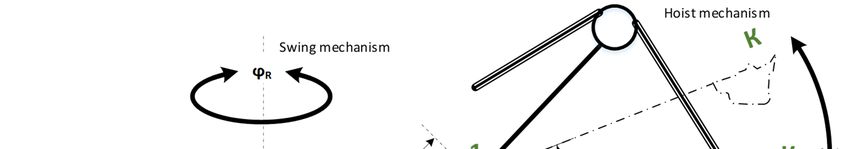
E3S Web of Conferences 280, 05013 (2021) https://doi.org/10.1051/e3sconf/202128005013
ICSF 2021
3 Excavator design features. Excavator- problem of the kinematics of the mechanical subsystem)
related coordinate systems and determining the positions of the crowd, hoisting and
swing mechanisms for a given position bucket in space
The most common type of powerful mining excavators in (the inverse problem of the kinematics of the mechanical
the conditions of Ukrainian mining enterprises are shovel subsystem). The main difficulty in determining the
excavators – EKG-5, EKG-8, EKG-10, EKG-12.5, EKG- position of the working bodies in space is that individual
20. These excavators have a similar design of the main mechanisms perform different types of movements, and
mechanisms, differing in geometric dimensions and the axes of rotation of individual mechanisms do not
minor structural elements. coincide with each other.
The further presentation will be carried out in relation to Figure 3 a simplified kinematic diagram of the
the EKG-8I excavator, in our opinion, the most common mechanisms of a power shovel excavator is presented.
model of a mining excavator in the conditions of the The position in space of the excavator bucket is fully
Kryvyi Rih iron ore basin. In fig. 2 shows the layout of described by the three-dimensional coordinates of the
the equipment on the platform of the EKG-8I excavator. digging point K .
The main movements of the excavator, performed The lift of the bucket is carried out by changing the
during the execution of the working cycle – lifting / angle of rotation around the axis passing through point 1,
lowering the bucket when digging and unloading perpendicular to the plane of the figure.
(hoisting mechanism); a linear movement of the dipper The extension and retraction of the bucket occur with
stick during digging and unloading (crowd mechanism) linear movement in the saddle bearing located at point 1
and rotation of the platform to the place of unloading and and is carried out by the linear movement of the dipper
digging (swing mechanism). We do not mention the stick LN . The platform rotates around a vertical axis
mechanism of the excavator's travel, since the movement passing through its center of mass and is carried out by
of the excavator is carried out separately from the changing the rotation angle R . Figure 4 illustrates the
working cycle.
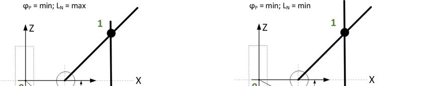
relative position of the boom and bucket of an excavator
The formulation of the problem of controlling the
at various limiting values of the angle P of the bucket
movement of the working bodies of an excavator requires
the solution of kinematic problems typical for and the linear movement of the dipper stick.
mechatronic systems: determining the position of the Thus, the controls action can be represented by the
bucket in space for the given values of the positions of vector = [ ], the state vector, that describing
the crowd, hoisting and swing mechanisms (the direct the position of the bucket, is given by the Cartesian
coordinates of the digging point = [ ].
Fig. 2. Equipment layout and geometrical dimensions of the EKG-8I excavator. 1 – revolving deck; 2 – body; 3 – auxiliary winch; 4 –
steps; 5 – two-legged stand; 6 – cables; 7 – boom; 8 – dipper stick; 9 – bucket suspension; 10 – bucket; 11 – rope; 12 – hoisting rope;
13 – driver's cab; 14 – roller circle; 15 – undercarriage; 16 – fence; 17 – entrance steps; 18 – steps; 19 – fence; 20 – rope; 21 – platform
on the boom; 22 – rope.
3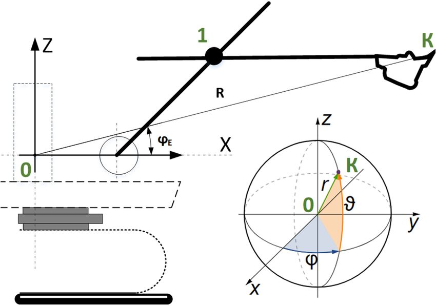
E3S Web of Conferences 280, 05013 (2021) https://doi.org/10.1051/e3sconf/202128005013
ICSF 2021
Fig. 3. Simplified kinematic diagram of the mechanisms of a power shovel excavator.
Fig. 4. Diagram of the mutual arrangement of the boom and dipper stick of an power shovel at various limiting values of the ascent
angle of the dipper stick P and linear movement of the dipper stick LN : а) = ; = ; b) = ; = ;
c) = ; = ; d) = ; = .
4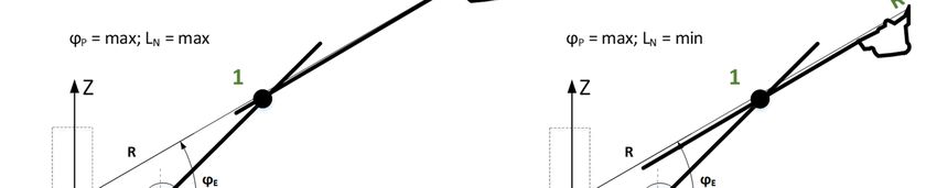
E3S Web of Conferences 280, 05013 (2021) https://doi.org/10.1051/e3sconf/202128005013
ICSF 2021
Since the working bodies of the excavator make two Then the spherical coordinates of the point K can be
different rotational movements, it is most natural to determined as follows:
consider the movement of the working bodies of the
excavator in a spherical coordinate system. The center of r K X2 K Z2
the spherical coordinate system of the excavator is located (2)
at point O on the platform rotation axis at a height equal arctan K Z / K X
to the height of the boom heel attachment, Fig. 5, Fig. 2.
The transition from a spherical coordinate system to
three-dimensional Cartesian coordinates is carried out
using the well-known expressions:
= ( ) ( )
= ( ) ( ) (3)
= ( )
Formulas (1-3) give us a closed solution to the direct
problem of excavator kinematics and determine the
equations for the transformation of the excavator control
coordinates ( , , ) to the Cartesian coordinates of
the digging point ( , , ).
5 Solution of the inverse problem of
Fig. 5. Spherical coordinate system associated with the power
shovel. power shovel kinematics
It is necessary to determine the excavator control
In this case, the spherical coordinate will be equal
coordinates ( , , ) using the specified Cartesian
to the angle of rotation of the power shovel revolving deck
coordinates of the position of the digging point .
, the spherical coordinate r will be equal to the length
The transition to spherical coordinates from Cartesian
of the segment 0 , the spherical coordinate will be
coordinates is carried out using the well-known
equal to the angle 0 (angle ). expressions:
The traditional way to derive kinematic equations for
backhoe/excavator or generic robots is to start with =
Denavit-Hartenberg parameters and transformation ⎧
matrices [15]. In this paper, a less traditional approach = (4)
will be used to take advantage of the fact that the stick and ⎨
bucket move in a plane that is rotated by the swing joint ⎩ =√ + +
(see Fig. 4). Taking advantage of this fact, the position Using equations (2), we obtain the following relations:
vectors can first be derived using spherical coordinates
and then converted into Cartesian coordinates (Fig. 5). =
With this location of the center of the coordinate system ( )
( ) (5)
and the accepted direction of the coordinate axes of the =
( )
orthogonal Cartesian coordinate system, the level of the
excavator is characterized by a negative value of the And finally, based on equations (1), we get the
coordinate . follows:
K Z LAN sin A
4 Solving the direct problem of power shovel P arctan
K X R0 LAN cos A
kinematics
K X R0 LAN cos A
It is necessary to determine the Cartesian coordinates of LN N1 (6)
cos P
the position of the digging point ( , , ) according to
the specified values of the control coordinates of the Y
R arctan
excavator – the linear movement of the shovel , the X
angle of the boom , the angle of rotation of the platform
. When solving the inverse problem of power shovel
Consider how the coordinates and of the spherical kinematics, it is necessary to take into account that not all
coordinate system are related to the lift angle and points in space ( , , ) are reachable, which is
linear movement of the shovel . associated with the existence of design constraints on the
Let's define the coordinates of the point K in the control coordinates of the excavator.
coordinate system 0 . Therefore, equations (4–6) must be supplemented
with the following restrictions:
= + ( )+( + ) ( )
(1)
= ( )+( + ) ( )
5
E3S Web of Conferences 280, 05013 (2021) https://doi.org/10.1051/e3sconf/202128005013
ICSF 2021
LN min LN LN max point 2. Since a part of this trajectory went beyond the
limits of the excavator's working area, a curvilinear
P min P P max (7)
section was formed in its middle part, corresponding to
R min R R max movement along the border of the working area.
Equations (4–6) subject to constraints (7) gives us a Table 1. Dimensions of the power shovel EKG-8I
closed solution for the inverse problem of excavator
Parameter Value
kinematics.
Boom length, m 13.35
– Tilt angle of boom, deg 47
6 Computational experiment Dipper stick length, m 11.425
Dipper stick stroke, m 4.3
To validate the obtained expressions, a number of – Distance from the revolving deck rotation axis to
calculations were performed using the example of the the boom heel attachment point, m
EKG-8I excavator. The overall dimensions of this – Dipper stick length minus dipper stick stroke, m
excavator used in the calculations are shown in Table 1. – Distance from the point of attachment of the
boom heel to the saddle bearing, m
Fig. 6 shows the results of calculations of the working area
– The minimal value of dipper handle position,
of the EKG-8I excavator, which shows the entire area of m
0
space reachable by the excavator bucket under the – The maximal value of dipper handle position,
constraints indicated in Table 1. The working area of the 4,3
m
EKG-8I excavator has a complex spatial shape, limited in – The minimum value of the angle of the
the front and rear by areas of the sphere. -90
hoisting mechanism, deg
Using the obtained expressions, a number of – The maximal value of the angle of the
45
trajectories were calculated for moving the bucket after hoisting mechanism, deg
the end of digging from point 1 to point of unloading the – The minimum value of the swing angle of the
0
bucket 2 (Fig. 7). power shovel revolving deck, deg
Trajectory 1 is obtained with the uniform motion of all – The maximum value of the swing angle of
excavator mechanisms. The Trajectory 2 was obtained by the power shovel revolving deck, deg (determined by 120
implementing a rectilinear movement from point 1 to the parameters of the power shovel working area)
Fig. 6. Working area of the power shovel EKG-8I.
Trajectory 3 was obtained by sequentially turning the The calculations showed that the length of these
platform and then lowering the bucket to point of trajectories differs significantly: from 25 m (Trajectory 2)
unloading 2. to 33 m (Trajectory 3), which is 32%.
The implementation of Trajectory 1 and Trajectory 2
requires the simultaneous coordinated operation of the
electric drives of all the main mechanisms of the Conclusion
excavator, which may require high qualifications of the The analysis of the mechanical structure of a mining
operator. Trajectory 3 is ensured by the sequential bucket excavator was carried out, which made it possible
operation of the electric drives of the main mechanisms of to solve the inverse problem – according to a given
the excavator. trajectory of movement of the working body, taking into
account technological limitations, at each point, the
coordinates of individual actuators were calculated. The
6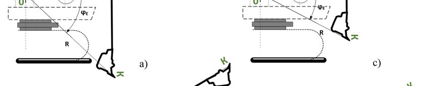
E3S Web of Conferences 280, 05013 (2021)                                                            https://doi.org/10.1051/e3sconf/202128005013
ICSF 2021

       obtained trajectories of movement show the available                  7.    R.H. Bichop, New York, CRC Press, Mechatronic
       possibilities for optimizing the operation of mining                        Systems, Sensors, and Actuators: Fundamentals and
       excavators, in particular, for minimizing the length of                     Modeling, 712 (2007)
       trajectories. However, it should be borne in mind that only           8.    J. Kitzig, G. Bumiller, IEEE International
       the length of the trajectory cannot serve as an optimization                Instrumentation and Measurement Technology
       criterion, since it does not take into account the speed of                 Conference, Evaluation of Power Quality
       movement of the bucket along the trajectory and the                         Measurement System Concept using an experimental
       associated energy costs of individual mechanisms, in                        setup, 1, 7, (2019)
       which not only the speeds and accelerations but also the
                                                                             9.    C. Wu Keng, Academic Press, Switch-Mode Power
       equivalent moments of inertia change during the
                                                                                   Converters, Chapter 10 – AC-DC Power-Factor
       movement.
                                                                                   Correction Supplies, (2006)
                                                                             10.   J. T. Betts, Philadelphia, Pennsylvania: SIAM Press,
                                                                                   Practical Methods for Optimal Control Using
                                                                                   Nonlinear Programming (2nd ed.) (2010).
                                                                             11.   V. Tytiuk, I. Lutsenko, I. Oksanych, Zh. Rozhnenko
                                                                                   Eastern      European      Journal   of    Enterprise
                                                                                   Technologies. 90, 9 (2017)
                                                                             12.   W.M. Zaw'jalow, I.Ju. Semykina, Izwestija
                                                                                   Tomskogo        politechnitscheckogo     uniwersiteta,
                                                                                   Matematitscheckaja       model'     mechanitscheckoj
                                                                                   tschacti wsaimocwjasannych jelektropriwodow
                                                                                   napora i pod#ema kar'ernogo jekckawatora. 310, 4,
                                                                                   (2007)
                                                                             13.   V. Tytiuk, M. Baranovskaya, D. Meleshko,
       Fig. 7. Trajectories for moving the bucket after digging to the             O. Chornyi, Electromechanical and energy saving
       point of bucket unloading                                                   systems, Mathematical modeling of group drives
                                                                                   push and lift electric excavator mechanisms, 33, 7
           The analysis of the energy costs of individual                          (2016)
       mechanisms, which is planned in the future, depending on              14.   B.M. Wilamowski, New York, CRC Press, Control
       the specified trajectory of the working body, will serve as                 and Mechatronics (The Industrial Electronics
       the basis for optimizing the energy consumption and                         Handbook), 728, (2011)
       productivity of mining excavators when performing a full              15.   J. G. Frankel, MS thesis. The Georgia Institute of
       working cycle and can automate the processes of                             Technology, G.W. Woodruff School of Mechanical
       controlling the position of its individual mechanisms.                      Engineering, Development of a Haptic Backhoe
                                                                                   Testbed (2004)
       References
       1.   B.C. Kwaginidze, Ju.A. Antonow, W.B. Korezkij,
            N.N. Tschupejkina, Ekckawatory na kar'erach.
            Konctrukzii, jekcpluatazija, ractschet. (M., Gornaja
            kniga, 409, 2009).
       2.   N. Kyura, Н. Oho, IEEE/ASME Transactions on
            Mechatronics,       Mechatronics     an     industrial
            perspective, 1, 6 (1996).
       3.   A.E. Kosjaruk, Problemy sozdanija perspektiwnych
            sistem elektropriwodow i NKU w gornych
            maschinach,        Sowerschenctwowanie         sistem
            uprawlenija elektrooborudowaniem kar'ernych
            gornych maschin, 1, 5, (2006)
       4.   R.P. Bishop, CRC Press. Taylor & Francis Group,
            Mechatronics : An Introduction, 285 (2006)
       5.   Stanley M. Shinners, Lockheed Martin Federal
            Systems John Wiley & Sons, Inc., 1998 ISBN: 0-471-
            24906-8
       6.   N K Kuznetsov et al, J. Phys.: Conf. Ser.,
            Investigation of efficiency of electric drive control
            system of excavator traction mechanism based on
            feedback on load, 1, 7 (2018)

                                                                         7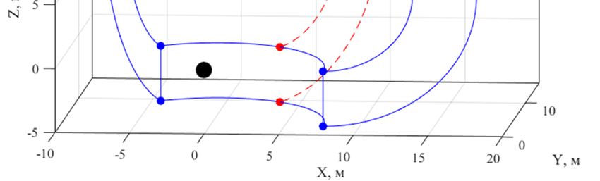

You can also read