Development of Microstrip Antenna for Satellite Application at Ku/Ka Band
←
→
Page content transcription
If your browser does not render page correctly, please read the page content below

Journal of Communications Vol. 16, No. 4, April 2021
Development of Microstrip Antenna for Satellite
Application at Ku/Ka Band
Farooq Al-Janabi1, Mandeep Jit Singh1, and Amar Partap Singh Pharwaha2
1
Department of Electrical, Electronic and Systems Engineering, Faculty of Engineering and Built Environment,
Universiti Kebangsaan Malaysia, 43600 Bangi, Selangor, Malaysia
2
Department of Electronics and Communication Engineering, Sant Longowal Institute of Engineering and Technology,
Longowal 148106, Distt. Sangrur, Punjab, India
Email: p95307@siswa.ukm.edu.my; mandeep@ukm.edu.my; aps.aps67@gmail.com
Abstract—Antennas are the most important unit in almost all result, lot of companies made their way to the satellite
wireless communications, which played the key of transmitting communication to overcome the shortcuts that land
the radiating electromagnetic waves after converting it from infrastructure cannot cover and develop. The presence of
electrical signal. In this paper, designed an antenna that is
capable to operate at frequencies between 12 GHz – 18 GHz for the antenna in the satellite communication system is of
Ku band, and 26.5 GHz – 40 GHz for Ka band. This antenna great significance, and as such cannot be eliminated. The
was designed to overcome the narrow bandwidth, low gain, and modern society has evolved and moved into the
large size of most satellite application antennas. By using a information age, and with this evolution, there are higher
square shaped patch on a 4.3 dielectric constant substrate, requirements for antenna. Thus, it becomes crucial to
modified and optimized the dimensions of the patch element, study multiband and miniaturized antennas [3]. Besides
this antenna operated on dual-band frequencies between 12 GHz
– 18 GHz and 26.5 GHz – 40 GHz, which satisfies the required the many advantages of characteristic microstrip antennas,
bandwidth for satellite application. The antenna design was they additionally have three basic disadvantages: narrow
simulated using CST Microwave Studio software to analyze and bandwidth, low gain, and quite large size. These
evaluate the performance of the antenna design visibility. parameters are further degraded by the compact antenna
Index Terms—Communication, satellite, antenna, Ku band, Ka configuration, as the reason of relationship between the
band, 12 GHz – 18 GHz 26.5 GHz – 40 GHz, CST studio suite, antenna’s bandwidth, size, and efficiency. Apart from
design, simulation that relationship, there is also a relationship between the
gain and the antenna’s size. Typically, the gain of
electrically small antennas is lower than that of the large
I. INTRODUCTION ones [4].
An antenna is an electrical conductor or a system of Modern consumer level markets are mostly serviced
conductors or a combination of dielectric and conducting with cable and land line-based infrastructure for the
system which can radiate electromagnetic energy into delivery of two-way internet access. Due to the logistical
space and receive electromagnetic radiation from space and broadband limitations of this cable-based
[1]. The recent years shows the amazing improvement infrastructure the opportunity appears for the use of
made by researchers to enhance this field concerning Underneath band (Ku-band) and if possible Above band
lacks in antenna technology. Wireless communication has (Ka-band) satellite infrastructure to deliver broadband
various applications like Global Position System (GPS), communications to consumer level markets. As the
mobile phone, traffic radar, military, biomedical and absence of a cable network, and existing the satellite
aerospace area that antenna structure is the fundamental television infrastructure, the opportunity arises for the
part of these systems [2]. At the same time a significant combination of a Ka-band uplink capability with the
amount of usage is made into this field by various users already existing Ku-band down link that currently assist
as education systems, business, medicine, space, oil and the delivery of satellite television. As the antenna is
gas companies and may more. Therefore, enhancement widely available in different shapes sizes, with the same
should be considered also upon the communication field concept of electromagnetic operating principles. Modern
and its infrastructure as its equally important. technology growth led to cutting everything sizes as it is
Considering the landline communication and equalize it a key feature for world advancement. Thus, wireless
with the size of planet and the various scattered human communication network developers certify that they keep
attentions, rural areas and industries, and massive ocean improvement a wireless communication component
ships makes it nearly impossible to cover all that area and which makes the devices to be lighter and easy to
provide direct access among the different users. As a navigate. Thats the reason why the radio communication
antenna developers should make a small-sized antenna, as
different frequencies handle different wireless
Manuscript received August 30, 2020; revised March 11, 2021. communication system and utilize small telecom
Corresponding authors email: p95307@siswa.ukm.edu.my.
doi:10.12720/jcm.16.4.118-125 operators modern devices. In order to suit the rapid
©2021 Journal of Communications 118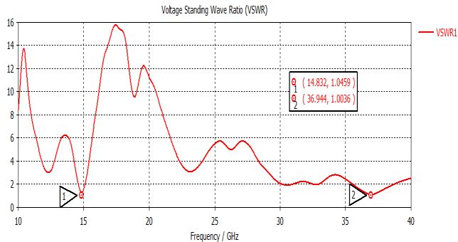
Journal of Communications Vol. 16, No. 4, April 2021

improvement of compact modern wireless devices,                   Still, the disadvantages exist in Ka-band as the weather
applying miniaturizing techniques will accompanied by             conditions impact the Ka-band more than at lower
few limitations as limited bandwidth, and a reduction of          frequencies. Thus, appropriate planning is needed for the
gain and efficiency radiation [5]. Although increasing the        implementation of well-designed ground systems,
thickness of the substrate to overcome the bandwidth,             network links reliability and resources to overcome the
will increase the surface power besides decreasing the            diverse weather effects [9].
radiation power, which will lead to poor radiation                   As the antenna are wildly used due to the light weight,
efficiency. Also, satellite communication still challenging       small profile, low cost, and ease of fabrication. It is much
due to the requirements of the power and signal                   desirable to have a single antenna with a single feed point
polarization when using Ku-band at 12 GHz – 18 GHz,               which cover dual frequency bands than several antennas
and Ka-band at 26.5 GHz – 40 GHz [6].                             for each frequency band [10]. Therefore, proposing a
   One of the main used technologies today for high-              square shaped microstrip antenna for satellite application
speed satellite internet is the Ku-band. Ku-band which is         that operate at Ku and Ka band. The proposed dual band
a part of the electromagnetic spectrum, is the lower              antenna is a well solution for high frequency applications,
portion among the three NATO K bands that operate in              as it has a small compact size, and operate at both bands
ranging frequencies from 20 GHz to 40 GHz, as Ku-band             with a good return loss and good Voltage Standing Wave
operates from 12 GHz to 18 GHz. It is widely used in the          Ratio (VSWR). The requirement and the mechanism of
satellite communications world. Reliable for the higher-          the antenna been collected to realize the design
powered satellite services used in digital TV to include          specification, that included details of the antenna's
news feeds, educational networks, teleconferences, sports,        geometrical parameters and the dielectric substrate. The
entertainment       programming,      and      international      antenna’s design process been determined based on the
programming. As well as, using it in Very Small Aperture          specifications of the certain application of the antenna.
Terminal (VSAT) systems on ships, for commercial
aircraft, and by NASA in space. Some of the Ku-band                         II. ANTENNA DESIGN METHODOLOGY
advantages that the power of uplink and downlink can be
                                                                     Satellite system is one of the supremely important
increased as needed, it is frequently better over lower
                                                                  application of microstrip antenna. Mobile communication
frequency microwave bands as that shorter wavelength              needs small sized, low-cost, and low-profile antennas.
can separate the signals of different communication               Microstrip patch antenna has all these requirements and
satellites with smaller parabolic antenna, it offers the          various types of microstrip antennas have been designed
flexibility for the users with freedom from land                  to be used in mobile communication systems. For satellite
operations making it easier to find a properly functioning        communication, circularly polarized radiation patterns are
dish site, and most importantly it is generally cheaper           required and can be attained by using either square or
option [7].                                                       circular patch with one or two feed points, due to the
   The applications of Ka-band system involve two-way             massive distance between the earth and satellite [11].
broadband internet, VSAT networks, enterprise                        A microstrip patch antenna is used for generally
applications, remote area communications, mobile                  narrowband applications. It has a wide-beam which is
backhaul, defense applications, satellite news gathering,         made by etching the design pattern on the metallic
and disaster management Since the commercial VSAT                 surface over a dielectric insulating base, a continuous
system operate in Ku-band; yet, a need for much wider             metal layer in the opposite side of the strip forms a
bandwidth make Ka-band frequencies more outstanding               ground plane. Microstrip patch antennas can be found in
for future commercial VSAT system. At higher                      many shapes, common shapes are regular like square,
frequencies the short wave has the lead of allowing               rectangular, circular, triangular etc. but in fact any
compact terminals and antennas to support high                    irregular shape is possible. Regular shapes are generally
bandwidth applications. Since the need for bandwidth, the         chosen because of ease of analysis, ease of fabrication,
up and down links have moved from the Ku-band to the              attractive radiation characteristics and low cross radiation
Ka-band. There are a host of wide band systems being              properties [12]. The radiation in microstrip patch
presented for Ka-band also, as Astrolink, Spaceway and            antennas is due to the fringing fields between the edge of
Teledesic, which proposed to afford multimedia services           the patch and the ground plane. A thick substrate with a
to desktop computer-size terminals [8]. Narrow band and           very low dielectric constant is suitable for good antenna
wide band systems are both reliable because they offer            performance since it provides a larger bandwidth, better
greatly higher capacity and low user costs compared to            efficiency, and better radiation. But in such a scenario,
traditional systems. As the bandwidth need keep                   the antenna size increases. Thus, to reduce the size, high
increasing, the carrier frequencies will keep moving to           dielectric constants substrate must be used which have a
higher bands. The Ka-band so far still in various stages of       narrow bandwidth and less efficient. Hence a proper
development. Operating in the Ka- band offers more                trade-off must be done at the designing stage to realize
advantages over usual satellite networks operating Ku-            antenna performance improvement at a particular
band and lower frequencies, that because of the high gain         operating frequency and constrained physical dimensions
antenna in Ka-band has comparing to lower frequencies.            [13].

©2021 Journal of Communications                             119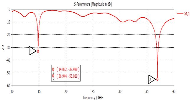
Journal of Communications Vol. 16, No. 4, April 2021

   Microstrip antenna feed techniques can be categorized
as two methods, the contacting and non-contacting. In the                                                                     (1)
contacting method, the Radio Frequency (RF) Power is
fed directly to the radiating patch using a connecting               where, is the patch width,      is the free space velocity
element such as a microstrip line. The microstrip line and           of light (       ), is the resonant frequency, and is
the coaxial probe are examples of contacting method. In              the substrate dielectric constant. The length of the
the non-contacting, electromagnetic field coupling will be           antenna patch can be found as shown in Eq. (2).
implemented to transfer the power between the microstrip
line and the radiating patch. Techniques that are in these                                                                    (2)
non-contacting methods are aperture coupling and
                                                                     where, is the patch length,         is the effective length,
proximity coupling. The feed technique that will be used
in this paper is microstrip line feed. Microstrip line feed          and   is the extended length.
is one of the easiest methods to fabricate, by conducting
strip connecting to the patch and therefore can be                                                                            (3)
consider as extension of patch. It is simple to model and
easy to match by controlling the inset position. However,            where, is the free space speed of light (            ), and
as the substrate thickness increases, surface waves and                   is the effective dielectric constant.
spurious feed radiation increase, which for practical
designs limit the bandwidth and the introduction of
                                                                                                                              (4)
coupling between the feeding line and the patch, which
leads to spurious radiation and the required matching                where,   is the substrate height.
between the microstrip patch and the 50 Ω impedance
feeding line [14].
   The feed-lines and the radiating patch are usually                                                                         (5)
photo-etched on the dielectric substrate. The substrate can
be thick or thin, and must be chosen with permittivity                  The proposed antenna structure phases started by
between 2.2 and 12. Flame Retardant 4 (FR4) materials                having a 5 mm 5 mm square shaped patch, second
response to environment, such as moisture diffusivity and            phase has an outer square shaped patch with 0.3 mm
moisture concentration, can also impact the performance              width, third phase added a center square shaped patch
of the design. The electrical performance of advance                 with 2.5 mm width, fourth phase added a middle square
materials is often compared to a standard FR4 baseline               shaped patch with 0.3 mm width, fifth phase added an
which consists of standard copper foil laminated to a core           inner square shaped patch with 1.25 mm width, sixth
of woven E-glass reinforcement impregnated with                      phase added a 1.95 mm 1.95 mm slot between the outer
unmodified FR4 epoxy resin. Therefore, the electrical                square and middle square shaped patch, seventh phase
performance of design using baseline of standard FR4                 added a 0.625 mm 0.325 mm slot between the middle
can be improved by changing one or more of its                       square and inner square shaped patch, the last phase were
components.                                                          adding a 0.325 mm 0.425 mm slot between the middle
   The proposed microstrip patch antenna designed as a               square and inner square shaped patch, both of second and
square shaped, while having an additional slot between               third slots are in between the middle square and the inner
the square shaped patch as shown in Fig. 1. The model                square. This process is meant to reach the final results
been adjusted and optimized for the best results. That               that aims to operate the antenna at dual satellite
ensures the desirable qualities as better efficiency, larger         applications frequencies.
bandwidth, and better radiation [15]. The first slot                    The antenna, which is useful for radio transmission and
between the outer square and middle square has a width               reception signals, its own electric energy can be
of 0.95 mm and length of 1.95 mm, second slot has a                  converted to electromagnetic energy. The antenna can be
width of 0.325 mm and length of 0.625 mm, and third                  represented as a transitional structure between free-space
slot has a width of 0.425 mm and length of 0.325 mm,                 and a guiding device. It is the last element in the
both of second and third slots are in between the middle             transmission side, when the first element is receiving side.
square and the inner square. Furthermore, the antenna                Therefore, the antenna is considered as an integral part of
designed with 4.3 dielectric constant substrate and one              all wireless communication systems. The final
feeder line, the design been operating at two frequencies            dimensions of the whole antenna structure are (10 mm
where it been functioning between 12 GHz to 18 GHz                   10 mm) with thickness of 1 mm. The antenna is designed
frequency for Ku-band, and 26.5 GHz to 40 GHz                        over Flame FR4 substrate with 0.025 dielectric loss
frequency for Ka-band. As for the design procedure, the              tangent [17]. the square shaped patch having a dimension
dimensions of the proposed antenna been calculated using             of (5 mm         5 mm) with a microstrip feedline at a
basic equations, the width of the antenna patch can be               distance of 2.5 mm from patch. The antenna parameters
obtained using Eq. (1) [16].                                         measurements are shown in Table I.

©2021 Journal of Communications                                120
Journal of Communications Vol. 16, No. 4, April 2021

                                                                         the proposed design, is measured from 10 GHz to 40 GHz
                                                                         frequency and 0 to -60 dB return loss parameter, at Ku
                                                                         band it has a return loss of -32.988 dB at 14.832 GHz,
                                                                         and Ka band has a return loss of -55.029 dB at 36.944
                                                                         GHz. This good matching ensures a longer antenna
                                                                         radiating distance.
                                                                            The bandwidth of the antenna is the range of
                                                                         frequencies within which the performance of the antenna,
                                                                         with respect to some characteristic, conforms to a
                                                                         specified standard. Impedance bandwidth from the
                                                                         impedance point of view identifies the range of
                                                                         frequencies, where more than 90% of the power applied
Fig. 1. Microstrip antenna geometry                                      to the input terminals of the antenna is accepted. The
                                                                         impedance bandwidth over a frequency range can be
                  TABLE I: ANTENNA PARAMETERS
                                                                         indicated in terms of return loss (S parameters). The
                                                                         proposed antenna has a wide band at both frequencies,
 Parameters                 Description               Value (mm)
                                                                         which satisfies the requirements of the satellite
                    Ground and substrate width            10             applications [20]. The Ku band has bandwidth of 0.5055
                     Patch outer square width             5              GHz, which operates between 14.587 GHz and 15.093
                    Patch middle square width            2.5             GHz. The Ka band has a bandwidth of 3.028 GHz, that
                     Patch inner square width            1.25
                     Microstrip feed line width          0.4             operates between 35.586 GHz and 38.615 GHz.
                    Ground and substrate length           10
                     Patch outer square length            5
                    Patch middle square length           2.5
                     Patch inner square length           1.25
                    Microstrip feed line length          2.5
                      patch outer slot length            1.95
                      patch inner slot length           0.625

  The parameters of the proposed square shaped patch
antenna been optimized using CST studio suite software.
The resulting dual band antenna is suitable for satellite
                                                                         Fig. 2. Antenna return loss at Ku and Ka band
communication systems, as result and discussion will
show that it operated at the Ku-band (12 GHz – 18 GHz),
and Ka-band (26.5 GHz – 40 GHz).

                III. RESULTS AND DISCUSSION
   The simulation results for the proposed antenna are
presented, the investigation and analysis conducted about
the satellite applications, especially for Ku frequencies
that operate at 12 GHz to 18 GHz, and Ka frequencies
that operate at 26.5 GHz to 40 GHz. The complete
simulation and modeling for the designed dual band                       Fig. 3. Antenna VSWR at Ku and Ka band
antenna conducted using CST software. The simulation
process started from designing the proposed antenna                         In wireless communications, the impedance bandwidth
based on the size required, followed with addition slots                 is defined as the range of frequencies over which the
between the patch square shapes of the design. The                       antenna return loss is greater than 10 dB or a VSWR of at
square shape patch was used to operate on Ku and Ka                      most 2 dB [21]. The return loss of the antenna and the
band, were the additional slots was used to enhance the                  VSWR are dependent on the antenna reflection
    and gain response of the antenna. The final operating                coefficient. The reflection coefficient can be defined as
frequencies were 14.832 GHz and 36.944 GHz, which are                    the ratio of the reflected wave to the incident wave. The
suitable for satellite application at Ku band and Ka band                VSWR of the conventional design is shown in Fig. 3.
[18].                                                                    VSWR is a reflection of the        response, as the VSWR
   Reflection coefficient       shown in Fig. 2 shows the                below 2 dB is suitable the most for antenna applications,
amount of power that is reflected back at the port of the                which means that a good radiation pattern is possessed by
antenna due to mismatch from transmission line, if                       the antenna if the VSWR is as low as possible [22]. The
             dB that means 90% of power excited been                     response of the antenna that is measured from 10 GHz to
transmitted [19]. The response of the return loss      for               40 GHz frequency and VSWR from 0 dB to 16 dB, it

©2021 Journal of Communications                                    121
Journal of Communications Vol. 16, No. 4, April 2021
shows that the antenna having a good match in terms of represent the lowest gain of the beam pattern. The
VSWR, as the proposed design had a good match of antenna radiation pattern can have a directional beam
1.0459 dB for Ku band, and Ka band had 1.0036 dB, pattern radiation [25]. The gain for Ku band shows a
were the maximum VSWR showed 16 dB. As both Ku positive value of 1.83 dBi while the far field of Ku band
and Ka bands has less than 2 dB, this design is satisfying shows a radiation efficiency of -4.417 dB, total efficiency
the requirements for operating at dual band frequency of of -4.419 dB, and minimum gain of -24.2 dBi. At Ka
satellite applications. band the gain shows a positive value of 4.95 dBi besides
Antenna gain is a significant parameter that can be the far field of Ka band that shows the radiation
used to describe the characteristics of the antenna’s efficiency of -2.444 dB, total efficiency of -4.445 dB, and
radiation, the gain of the antenna is described as the minimum gain of -32.3 dBi, making the antenna
performance of an antenna, it is a measure that takes into successful to be used at the satellite applications.
count the efficiency of the antenna radiation and the
directivity [23]. Furthermore, it is expressed as in a given
direction, the ratio of the intensity to the radiation
intensity that would be obtained when the power gets
accepted by the isotopically radiated antenna. The
response of the proposed antenna gain of the frequency is
shown in Fig. 4, the response of the antenna that is
measured from 10 GHz to 40 GHz frequency and gain
from -2 dBi to 7 dBi, it has a peak gain of 2.3163 dBi at
14.832 GHz, and a peak gain of 4.8344 dBi at 36.944 (a)
GHz. The antenna frequency versus the gain, shows that
the antenna has a reasonable gain at 14.832 GHz for Ku
band and at 36.944 GHz for Ka band, also it shows a
slight gain drop at K band, it furthermore shows that the
maximum gain is about 6.2 dBi.
(b)
Fig. 5. (a) 3D plot at 14.832 GHz (b) 3D plot at 36.944 GHz
Fig. 4. Antenna gain vs frequency response
Summed up result of the single dimensional responses
shows for Ku band at 14.832 GHz, the proposed antenna
shows a return loss of -32.988 dB, wide Ku bandwidth of
0.5055 GHz at (14.587 GHz to 15.093 GHz), total gain of
2.3163 dBi, and a VSWR of a good match at 1.0459 dB.
(a)
Furthermore, the Ka band at 36.944 GHz has a return loss
of -55.029, wide Ka bandwidth of 3.028 GHz at (35.586
GHz to 38.615 GHz), total gain of 4.8344 dBi, and a
good VSWR match at 1.0036 dB.
The antenna performance can be known by its gain, as
it shows how good the antenna converts the input power
into radio waves designed to transmit in the required
direction [24]. Also, the positive gain is needed to reach a
good wave propagation. As a performance parameter of
the proposed antenna, the three-dimensional (3D) gain
pattern are shown in the Fig. 5 were, (a) represent 3D (b)
gain plot at 14.832 GHz, and (b) represent it at 36.944 Fig. 6. (a) E-Field at 14.832 GHz (b) E-Field at 36.944 GHz
GHz.
The red areas represent the maximum gain of the beam The antenna’s electromagnetic field observe the
pattern for the proposed antenna, while the blue color directional power radiated by the antenna. The radiation
©2021 Journal of Communications 122Journal of Communications Vol. 16, No. 4, April 2021
pattern of the antenna can be represented as a two- polarization, the gain that is evenly distributed has a main
dimensional (2D) or a 3D [26]. The 2D patterns can be lobe magnitude of 4.95 dBi.
given as slices through the 3D pattern. To define antenna The E-field radiation pattern cross-polarization main
radiation patterns, the spherical coordinate system is used. lobe magnitude is 19.6 dBV/m, besides a maximum
Considering the antenna is designed on yx-plane, The directivity at the main lobe direction of the E-filed
Electric Field (E-Field) and Magnetic Field (H-Field) can radiation pattern 46.0 degree, were the (3dB) angular
be observed by vertical polarized direction as E-plane beam width is 51.3 degree, and -4.5 dB side lobe level.
having phi = 90 for yz-plane, or a horizontal polarized H-field at 14.832 GHz for Ku band simulated results at
direction as H-plane having phi = 0 for xz-plane. Fig. 6 co-polarization main lobe magnitude is -35.6 dBA/m, and
shows the E-Field at Ku and Ka bands, while Fig. 7 main lobe directional is 8.0 degree.
shows the H-Field at both bands. The H-field cross-polarization radiation pattern wide
angular beam width (3dB) is 86.8 degree, the level of the
side lobe is -11.6 dB.
The co-polarization of H-field at 36.944 GHz for Ku
band simulated results main lobe magnitude is -34.4
dBA/m, and main lobe directional is 35.0 degree.
The cross-polarization of H-field radiation pattern
wide angular beam width (3dB) is 78.5 degree, were the
side lobe level is -7.9 dB.
The plotted simulated radiation pattern results of the
proposed antenna show the result for Ku band at 14.832
(a) GHz were the direction angle is shifted to the left side by
35.0 degree for E-field and H-field. Were, the result for
Ka band at 36.944 GHz shows the direction angle is
shifted to the left side by 46.0 degree for E-field and 35.0
degree at H-field. The misalignment of axis in the
measurement can cause a discrepancy which arise in
return an inaccuracy in obtaining the measured data.
IV. CONCLUSION
In this paper, a dual band microstrip antenna for
satellite application is presented and been simulated using
(b) CST studio suite, the proposed microstrip patch antenna
Fig. 7. (a) H-Field at 14.832 GHz (b) H-Field at 36.944 GHz
designed as a square shaped, the square shaped patch
The E-plane and H-plane can define the performance design had an added slots among the outer, middle, and
of an antenna that is linearly polarized. While the inner square shaped patches, the first slot between the
electric-field vector together with the direction of outer square and middle square had a width and length of
maximum radiation are contained in the former, the latter 0.95 mm 1.95 mm, second slot had a width and length
contains the magnetic-field vector and direction of of 0.325 mm 0.625 mm, and third slot had a width and
maximum radiation [27]. length of 0.425 mm 0.325 mm, both of second and
The polar coordinate that showing the antenna third slots are in between the middle square and the inner
radiation pattern, can show that both frequencies having a square, the antenna has a total 10 mm2 profile size and
directional pattern. The beam width of Ku band at E- uses an FR4 substrate material, to provide the best
Field were 94.5 degree, were Ka band has 51.3 degree. simulation results aimed at the return loss, VSWR, gain,
Also, at H-Field the beam width of Ku band was 86.8 and radiation pattern. It is clear from all the results
degree, were Ka band has 78.5 degree. obtained that the proposed design is successfully
The radiation pattern for E-field at 14.832 for Ku band, operating at Ku band and Ka band for satellite
shows an omnidirectional co-polarization characteristic, applications with great results. The antenna is capable to
the gain at the main lobe magnitude 1.83 dBi is evenly operate at 14.832 GHz frequency for Ku band, and
distributed. 36.944 GHz for Ka band. The simulated design showed a
The cross-polarization radiation pattern of E-field main return loss of -32.988 dB at 14.832 GHz, with a wide Ku
lobe magnitude is 16 dBV/m, it has a maximum bandwidth of 0.5055 GHz at (14.587 GHz to 15.093
directivity at the main lobe direction of the E-filed GHz), and total gain of 2.3163 dBi. The Ka band at
radiation pattern 8.0 degree, with (3dB) angular beam 36.944 GHz had a return loss of -55.029, wide Ka
width of 94.5 degree, and side lobe of -13.7 dB. bandwidth of 3.028 GHz at (35.586 GHz to 38.615 GHz),
At 36.944 for Ka band, the characteristic of the and a total gain of 4.8344 dBi. As the VSWR below 2 dB
radiation patter for E-field shows an omnidirectional co- is suitable the most for antenna applications, Ku band had
©2021 Journal of Communications 123Journal of Communications Vol. 16, No. 4, April 2021
a VSWR of a good match at 1.0459 dB, and Ka band had [12] W. H. Weedon and S. K. Cheung, “Ku-band low-profile
a good VSWR match at 1.0036 dB. As the positive gain and wideband satellite communication antenna (LPWSA),”
is needed to reach a good wave propagation, the 3D gain in Proc. IEEE International Symposium on Phased Array
pattern for Ku band showed a positive value of 1.83 dBi, Systems and Technology (PAST), 2016, pp. 1-7.
were at Ka band the gain showed a positive value of 4.95 [13] K. L. Wong, Compact and Broadband Microstrip
dBi. The width of the beam of Ku band at E-Field were Antennas, John Wiley & Sons, 2004.
94.5 degree, were Ka band had 51.3 degree. Besides, at [14] L. S. Chuan, S. Ru-Tian, and Y. P. Hon, “Ka-band satellite
H-Field the beam width of Ku band was 86.8 degree, communications design analysis and optimisation,” in
were Ka band had 78.5 degree. The designed antenna Defense Science and Technology Agency (DSATA)
showed a good return loss, that covers the satellite Horizons, 2015, pp. 70-78.
applications frequencies as well as having a low cost, [15] R. Deng, S. Xu, and F. Yang, “Design of a Ku/Ka quad-
good gain, and small profile size. band reflectarray antenna for satellite communications,” in
Proc. IEEE International Symposium on Antennas and
CONFLICT OF INTEREST Propagation (APSURSI), 2016, pp. 1217-1218.
[16] C. A. Balanis, Antenna Theory: Analysis and Design,
The authors declare no conflict of interest. Wiley, 2005.
[17] U. Ozkaya and L. Seyfi, “Dimension optimization of
AUTHOR CONTRIBUTIONS microstrip patch antenna in X/Ku band via artificial neural
Farooq Al-Janabi conducted the research, and analyzed network,” in Procedia-Social and Behavioral Sciences,
the data; Mandeep Jit Singh simulated the proposed 2015, pp. 2520-2526.
antenna, and conducted the results; Amar Partap Singh [18] M. Moniruzzaman, M. T. Islam, G. Muhammad, M. S.
wrote the paper; all authors had approved the final Singh, and M. Samsuzzaman, “Quad band metamaterial
version. absorber based on asymmetric circular split ring resonator
for multiband microwave applications” in Results in
REFERENCES Physics, 2020, pp. 1-16.
[19] S. Malisuwan, J. Sivaraks, N. Madan, and N. Suriyakrai,
[1] R. Garg, P. Bhartia, I. Bahl, and A. Ittipiboon, Microstrip “Design of microstrip patch antenna for Ku-band satellite
Antenna Design Handbook, Artech House Publishers, communication applications,” International Journal of
Boston, London, 2001. Computer and Communication Engineering, vol. 3, no. 6,
[2] R. Ludwing and P. Bretchko, RF Circuit Design: Theory pp. 413-416, 2014.
and Applications, 2nd ed., 2009. [20] N. Fugo, R. Kaewon, and S. Sirivisoot, “A comparison of
[3] I. J. Bahl and P. Bhartia, Microstrip Antennas, Artech various patch sizes and feed point positions of graphene
House, 1980. microstrip antenna for orthopedic implants,” presented at
[4] C. G. Christodoulou and P. F. Wahid, Fundamentals of 2015 Biomedical Engineering International Conference,
Antennas: Concepts and Applications, Prentice Hall of 2015.
India, 2004. [21] N. Sanil, P. A. Venkat, and M. R. Ahmed, “Design and
[5] F. Yang and Y. Rahmat-Samii, Electromagnetic Band Gap performance analysis of multiband microstrip antennas for
Structures in Antenna Engineering, Cambridge Univeristy IoT applications via satellite communication,” in Proc.
Press, 2009. Second International Conference on Green Computing and
[6] K. F. Lee, K. M. Luk, and H. W. Lai, Microstrip Patch Internet of Things (ICGCIoT), Bangalore, India, 2018, pp.
Antennas, World Scientific, 2017. 60-63.
[7] B. S. Kumar, “Design and optimization of microstrip patch [22] Y. Liu and Y. H. Mary, “One dual-polarization 10-40 GHz
antenna for satellite applications,” International Journal of planar array antenna for sattellite communication,” in Proc.
Research, vol. 7, no. 9, pp. 369-373, 2018. IEEE International Symposium on Antennas and
[8] A. Kandwal, “Compact dual band antenna design for Propagation and USNC-URSI Radio Science Meeting,
Ku/Ka band applications,” Advanced Electromagnetics, 2019, pp. 1213-1214.
vol. 7, no. 4, pp. 1-5, 2017. [23] R. Shrestha, D. E. Anagnostou, S. J. Horst, and J. P.
[9] S. C. Pavone, G. S. Mauro, L. D. Donato, and G. Sorbello, Hoffman, “Dual-frequency and dual-polarization antenna
“Design of dual circularly polarized sequentially-fed patch array for satellite deployment,” in Proc. IEEE Aerospace
antennas for satellite applications,” Applied Sciences, vol. Conference, 2016, pp. 1-6.
10, no. 6, pp. 1-11, 2020. [24] E. Mutluer, B. Döken, and M. Kartal, “A dual-band
[10] S. Viesse, S. Asadi, and M. K. Hedayati, “A novel compact frequency selective surface design for satellite
defected ground structure and its application in mutual applications,” in Proc. 18th Mediterranean Microwave
coupling reduction of a microstrip antenna,” Turkish Symposium (MMS), 2018, pp. 43-46.
Journal of Electrical Engineering and Computer Science, [25] K. M. Ho and G. M. Rebeiz, “Dual-band circularly-
vol. 24, pp. 3664-3670, 2016. polarized microstrip antenna for Ku/Ka band statellite
[11] K. Hati, N. Sabbar, A. El Hajjaji, and H. Asselman, “A communication arrays,” in Proc. IEEE Antennas and
novel multiband patch antenna array for satellite
applications,” in Procedia Engineering, 2017, pp. 496-502.
©2021 Journal of Communications 124Journal of Communications Vol. 16, No. 4, April 2021
Propagation Society International Symposium (APSURSI), than 50 research grants (national and international). Thus far,
2014, pp. 1831-1832. his publications have been cited 1480 times and his H-index is
[26] S. Dixit and S. Mahadik, “Design of multislot dual band 21. His research interests include communication antenna
patch antenna for satellite communications,” International design, radiowave propagation, satellite antennas, and IOT. Dr.
Journal of Scientific Engineering and Applied Science Singh currently serves as the Editor-in-Chief for the Greener.
(IJSEAS), vol. 1, no. 5, pp. 329-331, 2015. Journal of Electronics and. Communication and Associate
[27] C. Chen, S. Xie, X. Zhang, and Z. Ren, “A new space and Editor for Journal of Electrical and Computer Engineering,
terrestrial integrated network architecture aggregated Hindawi. He received several International and National Medal
SDN,” Journal of China Academy of Electronics and awards for his research and innovation. He currently the advisor
Information Technology, vol. 10, no. 5, pp. 450-454, 2015. of the Engineering Education Technical Division (E2TD),
Institute of Engineers Malaysia.
Copyright © 2021 by the authors. This is an open access article
distributed under the Creative Commons Attribution License Amar Partap Singh was born in
(CC BY-NC-ND 4.0), which permits use, distribution and Sangrur, Punjab in 1967 and received his
reproduction in any medium, provided that the article is
BTech degree in ECE from GNDU,
properly cited, the use is non-commercial and no modifications
or adaptations are made. Amritsar in 1990. He received his
MTech degree from REC, Kurukshetra
Farooq Al-Janabi was born in Basrah, in 1994 and PhD degree in 2005.
Iraq, in 1994. He received the B.S. Presently, he is a professor in ECE
degree in Electronics Engineering from department at SLIET, Longowal. Dr
the Infrastructure University Kuala Singh is credited with a professional experience of more than 24
Lumpur (IUKL), Selangor, Malaysia, in years. He has guided seven PhD thesis and six more students are
2017. He is currently pursuing the M.S. pursuing their PhD degrees under his supervision. He has
degree in Communication and Computer published more than 180 research articles in various national
Engineering at Universiti Kebangsaan and international journals/conferences and received various
Malaysia (UKM), Selangor, Malaysia. His current research awards including IETE Students Journal Award in 2006 by
interest includes antenna and propagation, and wireless IETE, New Delhi, Certificate of Merit in 2006, KF Anita Award
communication systems. in 2009, Sir Thomas Ward for the year 2010, and again KF
Anita Award in 2014 by the Institution of Engineers (India).as
Mandeep Jit Singh was born in born in Jiangsu Province, China, in 1978. He received the B.S.
Malaysia in 1975. He is a Professor at degree from the University of Science and Technology of China
the Department of Electrical, Electronic (USTC), Hefei, in 2001 and the M.S. degree from the
and Systems Engineering of the University of Florida (UF), Gainesville, in 2003, both in
Universiti Kebangsaan Malaysia (UKM) electrical engineering. He is currently pursuing the Ph.D. degree
and visiting Professor of Covenant with the Department of Electrical and Computer Engineering,
University, Nigeria. He is author and co- UF. His research interests include spectral estimation, array
author of more than 250 research articles signal processing, and information theory.
in antenna and microwave RF. He is also the recipients of more
©2021 Journal of Communications 125You can also read