DMI920 EVK G.hn Wave-2 Industrial - User Guide MaxLinear Confidential
←
→
Page content transcription
If your browser does not render page correctly, please read the page content below
DMI920
         G.hn Wave-2 Industrial
                 EVK
                   User Guide

                        MaxLinear Confidential
TBD/18        MaxLinear Confidential •083UGR00
                                       www.maxlinear.com • 083UGR00   i
DMI920 G.hn Wave-2 Industrial EVK User Guide                             Revision History

Revision History
Document No.     Release Date     Change Description
083UGR00         April 22, 2021   Initial release.

                                                MaxLinear Confidential
April 22, 2021                                        083UGR00                          ii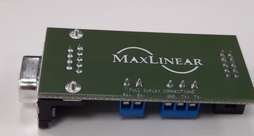
DMI920 G.hn Wave-2 Industrial EVK User Guide                                                                                                                   Table of Contents

Table of Contents
Introduction...........................................................................................................................................................................1
Wave-2 G.hn Spirit GRID......................................................................................................................................................1
Related Documentation .......................................................................................................................................................1

DMI920 Industrial Evaluation Kit.........................................................................................................................................2

Ordering Information............................................................................................................................................................6

DMI920 User Interface ..........................................................................................................................................................8

Laboratory Evaluation and Tests ......................................................................................................................................10
        Evaluation Software Tool ............................................................................................................................................10
        Network Performance Test..........................................................................................................................................10
                 Test 1: Dynamic Range Measurement in Flat Channel......................................................................................10
                 Test 2: RFC 2544 Throughput and Latency Test ...............................................................................................14
                 Test 3: Repeating Test .......................................................................................................................................16
                 Test 4: Adaptative Load Balancing and Latency Test ........................................................................................19
        RS-232/RS-485 Evaluation .........................................................................................................................................21
                 Test 1: Basic RS-232 Test .................................................................................................................................22
                 Test 2: Basic RS-485 Test .................................................................................................................................23
                 Test 3: RS-485 Multi-Node Test.........................................................................................................................24
        USB .............................................................................................................................................................................27
                 Test 1: Dynamic Range Measurement in a Flat Channel...................................................................................27

Appendix A: Coaxial Profile Evaluation ...........................................................................................................................31
Appendix B: Phone Profile Evaluation .............................................................................................................................31

Appendix C: Safety Recommendations ...........................................................................................................................32
        Avoiding Injuries ..........................................................................................................................................................32

Appendix D: RS485ACC Accessory for Industrial EVK ..................................................................................................33
        General description .....................................................................................................................................................33
        RS485 Half Duplex ......................................................................................................................................................34
        RS485 Full Duplex ......................................................................................................................................................35
        RS232 .........................................................................................................................................................................36

                                                                         MaxLinear Confidential
April 22, 2021                                                                       083UGR00                                                                                           iii
DMI920 G.hn Wave-2 Industrial EVK User Guide List of Figures
List of Figures
Figure 1: DMI920 Block Diagram ...........................................................................................................................................2
Figure 2: EVK External Interfaces ..........................................................................................................................................2
Figure 3: Industrial Multi-Medium Multi-Platform scenario .....................................................................................................4
Figure 4: 5-Pole Connector for MIMO 3-Wires .......................................................................................................................5
Figure 5: DMI920 Wave-2 Front Side.....................................................................................................................................6
Figure 6: Universal PLC Signal Splitter ..................................................................................................................................7
Figure 7: Test Setup for Two Nodes Based on TR208.........................................................................................................11
Figure 8: G.hn connections in SCT ......................................................................................................................................12
Figure 9: Test Diagrams for Repeating Point to Multi-point..................................................................................................16
Figure 10: Topology in SCT..................................................................................................................................................17
Figure 11: RS-232 Basic Use Case......................................................................................................................................22
Figure 12: RS-485 Basic Use Case......................................................................................................................................23
Figure 13: RS-485 Multi-node Modbus.................................................................................................................................24
Figure 14: 10pin RS-485 Interface Connected to the USB to the RS485 Cable (Half Duplex) ............................................25
Figure 15: CAS Modbus Scanner GUICAS Modbus Scanner GUI ......................................................................................26
Figure 16: Test Setup for 2 DMI920 Nodes with USB Based on TR208 ..............................................................................28
Figure 17: G.hn Connections Tab in SCT ............................................................................................................................29
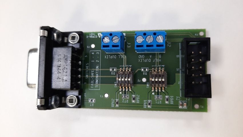
Figure 18: Fail-safe Status and Termination Resistor on PCB.............................................................................................33
Figure 19: RPU, RPD, and RT Resistors .............................................................................................................................33
Figure 20: RS485 Half Duplex..............................................................................................................................................34
Figure 21: RS485 Full Duplex ..............................................................................................................................................35
Figure 22: RS232 .................................................................................................................................................................36
MaxLinear Confidential
April 22, 2021 083UGR00 iv
DMI920 G.hn Wave-2 Industrial EVK User Guide                                                                                                                 List of Tables

List of Tables
Table 1: DMI920 PLC 5-Pole Connector ................................................................................................................................4
Table 2: G.hn Wave-2 Industrial EVK Contents .....................................................................................................................7
Table 3: Ordering Information for Telebyte’s PLC Evaluation Accessories............................................................................7
Table 4: DMI920 User Interface Buttons and LEDs ...............................................................................................................8
Table 5: Link Quality Indicator Description .............................................................................................................................9
Table 6: Secure Indicator Description ....................................................................................................................................9
Table 7: CONFIG Button ........................................................................................................................................................9
Table 8: DMI920 UDP Unidirectional Measurements (Mbps)...............................................................................................13
Table 9: DMI920 TCP Unidirectional Measurements (Mbps) ...............................................................................................13
Table 10: DMI920 RFC2544 Measurements (Mbps) – PLC MIMO 41 MHz (Profile 15)......................................................15
Table 11: DMI920 RFC2544 Measurements (Mbps) – PLC MIMO 50MHz (Profile 16).......................................................15
Table 12: Results RFC 2544 between the HE and the CPEx Test PLR 0% Bidirectional—Profile 16.................................18
Table 13: Results RFC 2544 between the HE and the CPEx Test PLR 0% Bidirectional—Profile 15.................................18
Table 14: Results of Latency with ALB On and Off ..............................................................................................................20
Table 15: Results RFC 2544 between the HE and the CPE3 Test PLR 0% Bidirectional—ALB off vs on ..........................20
Table 16: Serial Tunneling Config Layer Parameters...........................................................................................................21
Table 17: DMI920 UDP Unidirectional Measurements (Mbps) with USB Interface..............................................................30
Table 18: DMI920 TCP Unidirectional Measurements (Mbps) with USB Interface ..............................................................30

                                                                      MaxLinear Confidential
April 22, 2021                                                                  083UGR00                                                                                      v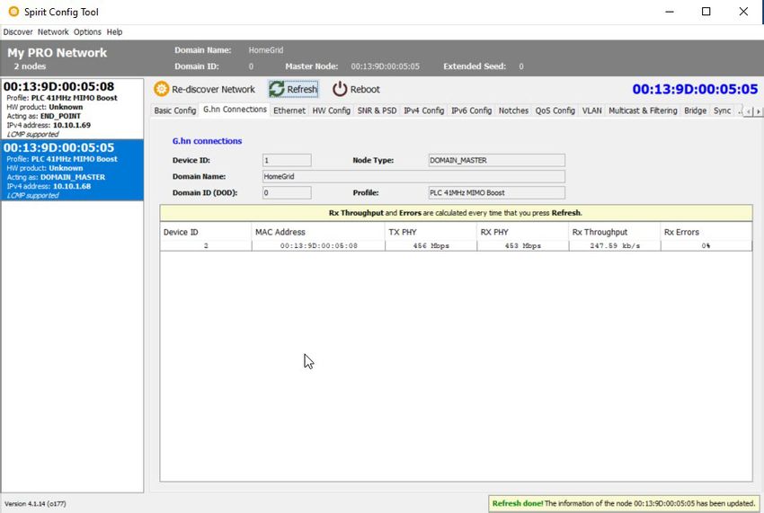
DMI920 G.hn Wave-2 Industrial EVK User Guide                                                                                 Introduction

Introduction
The scope of this document is to provide a guide to evaluate MaxLinear’s G.hn Wave-2 industrial design EVK solution for
powerline communications running Spirit GRID software.
    Note: The features described and performance data within this document are for guidance only, and they cannot be
    construed as any form of specification, guarantee, or contract between MaxLinear and the evaluator.
This document helps you to evaluate the powerline communications (PLC) smart grid and industrial solution feature set at
technical level using hardware and software tools provided in evaluation package. It also helps to learn the technology at
the same time as checking its real-world performance.
    Warning! The electrical safety of this evaluation kit (EVK) has not been fully evaluated against the requirements of the
    IEC 62368-1/EN 62368-1/UL 62368-1 (Audio/video, information and communication technology equipment – Part 1: Safety
    requirements) standard and this EVK cannot fulfill with all the relevant electrical safety requirements stated in such standard.

Before continuing, read carefully the “Appendix C: Safety Recommendations” on page 32.

Wave-2 G.hn Spirit GRID
MaxLinear’s Spirit GRID software is intended for smart grid and industrial applications using the G.hn
88LX5153A/88LX2741 and 88LX5152/88LX2720 chipsets for PLC.
The Spirit GRID software introduces new features to extend coverage such as MIMO Robust profiles and MAC relaying
(repeating) functionality which also enables increasing number of nodes supported in the same G.hn domain up to some
hundreds. Tree network topology is automatically built by the software based on one fixed head end (HE) node and rest are
end point (EP) nodes which can also act as repeaters. Data communication is only allowed between the EPs and HE. For
further information about the Spirit GRID, refer to the Spirit GRID Software User Guide (082UG) and the latest released
Spirit firmware release notes.

Related Documentation
■   Spirit GRID Software User Guide (082UG)
■   G.hn Industrial EVK Design Guide (036DG)
■   88LX5152 and 88LX5153 Data Sheet (072-5253DS)
■   88LX2720, 88LX2730, 88LX2740, and 88LX2741 Wave-2 G.hn AFE Data Sheet (081DS)
■   TR-208 Test Plan for Powerline Communication (PLC) Systems. For more information, go to the Broadband Forum
    (BBF) webpage. For more information, go to https://www.broadband-forum.org/download/TR-208_Issue-2.pdf.

                                                       MaxLinear Confidential
April 22, 2021                                                 083UGR00                                                                1
DMI920 G.hn Wave-2 Industrial EVK User Guide                                                                               DMI920 Industrial Evaluation Kit

DMI920 Industrial Evaluation Kit
MaxLinear G.hn offering introduces a new G.hn industrial multi-medium multi-interface EVK (DMI920) running the Spirit
GRID software that allows you to evaluate new industrial PLC applications. This new EVK provides new external interfaces
such as USB and RS485/RS232, SPI, as well as 1Gbps Ethernet RJ45 port. The industrial EVK running the Spirit GRID
software can only support powerline profiles. However, you can load a Spirit home networking software and use coaxial
and phone G.hn interfaces which are also available in this new multi-medium EVK.
The following figure shows the DMI920 block diagram with the main devices highlighted.

                  GbE              GPY115
                                                                                                                              G.hn
                                                                                                                           Coax / Phone
                                                                       Flash                          COAX/PHONE
                                                                                                      Coupling Unit
                                                                                  SPI TP

                                                            SGMII                                                             G.hn PLC
                                                                                           88LX2741                     (3 / 4 Wire Injection)
                                   XR22800                          88LX5153A              G.hn AFE          PLC
                  USB                        MDI
                                                   Fast
                                                              MII                                          Coupling
                                                                                                                                                 CH1+
                                                                                                                                                 CH1-
                                                 Ethernet           G.hn Wave-2
                                                                                                                                                 CH2+
                                                                                                                                                 CH2-
                                                   PHY                                                       Unit
                          I2C TP                                        BBP                88LX2741
                                                            UART
                                                                                           G.hn AFE

                                                                                                                            AC power
                                                                                                                       (100-240V / 50-60Hz)
                                                                                                                                                  phase
                                                                                            AC/DC
                 RS232/                                      3.3V                    5V                    Line trap                              neutral
                                   SP336E                    1.5V
                                                             1.1V    XR77103                power            Filter                               earth
                 RS485                                                                      supply

                                                                           ZCD TP

                                                    Figure 1: DMI920 Block Diagram

The DMI920 Industrial EVK provides the external interfaces shown in the following figure.

                        Eth                                                                                                      Eth
                        USB                                               G.hn                                                   USB
                        RS-485                   DMI920 EVK                                   DMI920 EVK
                                                                                                                                 RS-485
                        RS-232                                                                                                   RS-232
                        SPI                                                                                                      SPI

                                                   Figure 2: EVK External Interfaces

                                                            MaxLinear Confidential
April 22, 2021                                                        083UGR00                                                                              2
DMI920 G.hn Wave-2 Industrial EVK User Guide                                               DMI920 Industrial Evaluation Kit

Ethernet Interface
The Gigabit Ethernet port is provided by MaxLinear GPY115 Itemp device connected to the 88LX5153A’s SGMII interface.

USB Interface
The USB interface is provided by MaxLinear XR22800 device. The XR22800 is a hi-speed USB 2.0 device with an
embedded hub and the following four downstream USB functions:

■   10/100 Ethernet MAC and PHY.
■   UART.
■   Multi- master capable I2C controller.
■   Enhanced dedicated GPIO entity (EDGE) controller.
Only the Ethernet interface of the XR22800 is used to connect to the 88LX5153A’s device through the MII interface. An IP
address is configured for the USB interface, so this interface is transparent from the G.hn firmware.

SPI Interface
An API to read and write on the SPI interface is already provided in the G.hn SDK to manage this interface.

RS232/RS485 Interface
Both RS-232 and RS-485 interfaces are provided by the SP336E device. The SP336E is a MaxLinear serial
multi-transceiver device that contains both RS-232 and RS-485/RS-422 line drivers and receivers.
The SP336E is connected to the G.hn 88LX5153A through UART interface. The SP336E provides multiples modes but
only native configurations for RS-232, RS-485 half and full duplex modes are enabled by the Spirit software using its serial
tunneling component. It is in charge of packetize incoming bytes into packets, send them through G.hn, and do the opposite
in the receiver part.
For further information about new industrial EVK, refer to the following documents:

■   G.hn Industrial EVK Design Guide (036DG).
■   88LX2720, 88LX2730, 88LX2740, and 88LX2741 Wave-2 G.hn AFE Data Sheet.
■   88LX2741 Wave-2 G.hn Industrial AFE Data Sheet (073-2741DS).
■   DMI920 EVK design files.
This is a typical scenario where the industrial multi-medium multi-interface can replace the RS-485 devices to reduce wiring
and increase the connection distance.

                                                 MaxLinear Confidential
April 22, 2021                                           083UGR00                                                          3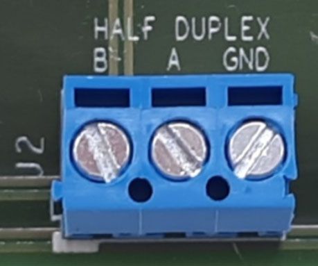
DMI920 G.hn Wave-2 Industrial EVK User Guide                                                           DMI920 Industrial Evaluation Kit

                                                                                                 Panel n                  Panel m
                                                                           G.hn
                                  DC
                                                                                              RS-485

                                  RS-485                                                         Panel 3
                                           Panel 3
                                           Pa

                                                                                                 Panel 2
                                  RS-485   Panel 2
                                           Pa

                                                                                                 Panel 1
                                  RS-485   Panel 1
                                           Pa

                                                      Control
                        RS-485
         Control unit                                  unit

                                                                 RS-485

                                                                                    G.hn to RS-485

                                    Figure 3: Industrial Multi-Medium Multi-Platform scenario

PLC coupling part
The DMI920 hardware user interface integrates a five-pole connector to connect power wires to couple PLC signal into
electrical network. Two wires for SISO and three or four wires for MIMO can be connected. For combination details, see the
following table.

Table 1: DMI920 PLC 5-Pole Connector
Coupling Mode                    Pole                  Comment
SISO 2 wires (P and N)           1 and 2               P to pin 1 and N to pin 2.
MIMO 4 wires                     1 and 2 for CH1       -
                                 3 and 4 for CH2
MIMO 3 wires                     1, 2, and 3           For example, Phase to pin 1, Neutral to pin 2 and Protective Earth to pin 3.
                                 Bridge 4 and 5

    Warning! You do not need to supply power in the PLC 5-pole connector to avoid any electrical discharge and injury. This is only
    intended for PLC signal.

                                                     MaxLinear Confidential
April 22, 2021                                                  083UGR00                                                              4
DMI920 G.hn Wave-2 Industrial EVK User Guide                                   DMI920 Industrial Evaluation Kit

                                 Figure 4: 5-Pole Connector for MIMO 3-Wires

                                           MaxLinear Confidential
April 22, 2021                                    083UGR00                                                   5
DMI920 G.hn Wave-2 Industrial EVK User Guide Ordering Information
Ordering Information
To evaluate and configure the adapters during the test, you can use the following elements:
■ MaxLinear’s DMI920 Wave-2 G.hn industrial evaluation board with the Spirit GRID 7.12 SR1 firmware loaded. Be
aware that two or more units are needed to execute the suggested test cases described in this document.
■ This document, DMI920 G.hn Wave-2 Industrial EVK Evaluation User Guide (083UG).
■ The Spirit Configuration Tool (SCT) 4.1.14 o178 (or higher) software application.
The following figure also shows the DMI920 Wave-2 front side.
Figure 5: DMI920 Wave-2 Front Side
MaxLinear Confidential
April 22, 2021 083UGR00 6DMI920 G.hn Wave-2 Industrial EVK User Guide Ordering Information
Table 2: G.hn Wave-2 Industrial EVK Contents
Part Number Package Content Description
2 × DMI920 Wave-2 G.hn industrial EVK G.hn Industrial IoT multi-medium (AC/DC PLC, coaxial,
phoneline), multi-Interface (1G Ethernet, RS485/232, USB,
SPI) evaluation kit with two G.hn adaptors
(88LX5153A+88LX2741).
PLC 5-pole connector -
RD-GRID-2DMI920KIT-01 DMI920 to the RS-485/RS-232 connector Accessory to interconnect DMI920’s 10-pin connector with
accessory. (RS485ACC) the RS485 or RS232.
2 × RS485 10pin ribbon cable Ribbon cable, IDC receptacle to IDC receptacle, 10 ways.
2 × USB cable USB Cable, type A plug to mini type B plug.
2 × IEC Mickey mouse electrical cable Mains cordset EU. Europlug IEC320 C5.
2 × Ethernet cable -
MaxLinear highly recommends t that you get at least two universal PLC splitter (3-port mains-PLC signal splitter for SISO
and vendor-independent MIMO following the TR-208 Test Plan for Powerline Communication (PLC) Systems in addition to
the DMI920 EVK. They are used to perform the proposed laboratory tests and help to control the attenuation between the
powerline boards. See Figure 6.
To purchase of this universal PLC (UPLC) kit, you can go to Telebyte Broadband (https://www.telebyteplc.com). The
following table lists the corresponding ordering information.
Table 3: Ordering Information for Telebyte’s PLC Evaluation Accessories
Part Number Package Content Number of Devices
GHN-SP-UPLC Universal PLC splitter 1
GHN-AT-PROG-UPLC-3-Slope Channel-slope programmable attenuator 1
GHN-SP-SPLCOMB-UPLC-3 3-Channel Splitter/Combiners 1
To perform the test cases described in the following sections, BNC Male-BNC Male 50Ω cables and several 20dB and
10dB 50Ω BNC attenuators can be also required. They are not included in the UPLC kit. However, you can purchase them
in most hardware and electronics stores. Other recommendable accessory from Telebyte Broadband is a 3-channel-slope
programmable attenuator (GHN-AT-PROG-UPLC-3-Slope), as well as 3-channel splitter/combiners
(GHN-SP-SPLCOMB-UPLC-3) for some multi-mode test cases.
The following figure shows the universal PLC signal splitter.
Figure 6: Universal PLC Signal Splitter
MaxLinear Confidential
April 22, 2021 083UGR00 7DMI920 G.hn Wave-2 Industrial EVK User Guide DMI920 User Interface
DMI920 User Interface
The main features provided by the DMI920 hardware user interface are:
■ Pairing (one button security setup, OBUS – ONLY Spirit Home Networking): Automatic generation of a random
domain name and encryption password. It is used to guarantee network security and exchange these parameters
between the adapters by using a single button push as defined by HomeGrid Forum for compliance and interoperability
purposes.
■ Unpairing (ONLY Spirit HN): Returns to the default security settings.
■ Manual factory reset.
■ Link quality indicator with a three-color LED. The three different levels of the link quality is shown in the receiver
adapter.
■ Reset: Manual reset of the board.
Table 4: DMI920 User Interface Buttons and LEDs
Definition Icon Function
CONFIG button CONFIG Used to implement the following tasks:
■ One button security setup (Pairing).
■ Return to default security settings (Unpairing).
■ Factory reset.
■ Force recovery mode (Power on device with CONFIG button pressed).
RESET button RESET Manual reset of the board.
Link Quality indicator Three-color code LED that indicates if the adapter has G.hn link.
It also shows the application throughput level available in the link (throughput indicator) and
also indicates if the adapter enters in power saving mode.
Secure” indicator LED that indicates whether the device is secure or not, that is, whether the device has
received/generated the network keys (so it belongs to a unique secure domain) or not.
Spirit home networking ONLY.
USB indicator LED that indicates the link and traffic through USB port.
MaxLinear Confidential
April 22, 2021 083UGR00 8DMI920 G.hn Wave-2 Industrial EVK User Guide DMI920 User Interface
The meanings of the various LEDs and buttons are given in the following tables.
Table 5: Link Quality Indicator Description
Color Adapter Status Meaning
OFF ON No G.hn link.
RED ON G.hn link is present and the estimated application throughput < 20Mbps (configurable)
ORANGE ON G.hn link is present and 20Mbps (configurable) < estimated application throughput < 40Mbps
(configurable)
GREEN ON G.hn link is present and estimated application throughput > 40Mbps (configurable)
BLINKING in RED, ON Tx/Rx activity in the G.hn port.
ORANGE, or GREEN
BLINKING in RED POWER When the adapter enters in power saving, this LED blinks once every 5s.
every 5s SAVING
Table 6: Secure Indicator Description
Secure LED State Meaning
OFF The device is not secure. It has neither received nor generated network keys (domain name and encryption
password).
ON The device is secure. It has either received or generated network keys).
SLOW BLINKING The device is in configuration mode (and can exchange network keys).
QUICK BLINKING The device is in return to default security settings mode” (unpairing).
Three FLASHES The device has received key from another secure device and has finished its configuration.
Table 7: CONFIG Button
Button Meaning
CONFIG ■ Press more than 2s (Secure indicator starts slow blinking) and release = The pairing procedure is started
and the configuration period is open.
■ Press more than 5s (Secure indicator starts quick blinking) and release = The security settings are set to
default values.
■ Press more than 10s (Secure indicator switches off) and release = A factory reset is performed.
Note: Some of the user interface buttons and LEDs only apply for Spirit home networking, for instance pairing
functionality.
MaxLinear Confidential
April 22, 2021 083UGR00 9DMI920 G.hn Wave-2 Industrial EVK User Guide Laboratory Evaluation and Tests
Laboratory Evaluation and Tests
Evaluation Software Tool
The SCT is a Java software tool to help you during the G.hn adapters testing.
The SCT enables reading and writing main configuration settings of the MaxLinear G.hn adapters belonging to same logical
network and it is used for most of the evaluation tests introduced in this section.
For more information about installation and use of SCT, refer to the Spirit Configuration Tool User Guide (052UG).
Network Performance Test
Test 1: Dynamic Range Measurement in Flat Channel
This test concentrates on two nodes network performance. You can measure the variation of the following variables as a
function of attenuation:
■ Physical throughput.
■ TCP throughput.
■ UDP throughput
Test Equipment
■ 2 × MaxLinear DMI920 EVK (one node with dmi920_v1_x-HE-GRID_flash-SPIRIT.v7_12_r820+5_cvs loaded and one
node with dmi920_v1_x-EP-GRID_flash-SPIRIT.v7_12_r820+5_cvs image loaded).
■ A dedicated HW network performance analysis system such as Ixia or Spirent's Smartbits.
■ Alternatively, use two PCs with one of the following software options:
Chariot SW from Ixia.
Iperf software (a public domain application that you can download for free), but the specific hardware and operating
system can place a limitation on the results. For instance, Windows PC usually limits iperf UDP performance as
client, so use of Linux is advised for UDP performance tests when possible.
■ Spirit Configuration Tool (SCT).
■ 2 x GHN-SP-UPLC.
■ Combined fixed attenuators.
■ BNC coaxial cables.
MaxLinear Confidential
April 22, 2021 083UGR00 10DMI920 G.hn Wave-2 Industrial EVK User Guide Network Performance Test
The following figure shows a test setup diagram that uses this test equipment.
Cat5
Traffic Traffic
Generator/ Generator/ PLC
Analyzer Analyzer
&RD[LDO
Power (filtered)
Power (non-filtered)
PLC adapter PLC adapter
(DUT1) (DUT2)
PLC to FRD[LDO PLC to FRD[LDO
P E N N E P
Variable
attenuator (Att1)
Variable
attenuator (Att2)
Variable
attenuator (Att3)
Filter
(optional)
Figure 7: Test Setup for Two Nodes Based on TR208
Warning! Yo do not need to supply power in PLC 5-pole connector to avoid any electrical discharge and injury. This is only
intended for PLC signal. For instance, you do not need to power the universal PLC splitter to run evaluation test cases.
Test Methodology
To perform this test:
1. Select the G.hn PLC profile to be tested (Spirit GRID supports PHYMNG.GENERAL.RUNNING_PHYMODE_ID=15 or 16,
default is 16 for DMI920) and configure it into the PLC adapters by using SCT.
2. Set an attenuation of 10dB between the adapters.
MaxLinear Confidential
April 22, 2021 083UGR00 11DMI920 G.hn Wave-2 Industrial EVK User Guide Network Performance Test
3. Check with the SCT the G.hn connections and note the PHY rates.
Figure 8: G.hn connections in SCT
4. Run the corresponding Ixia tests that measure TCP throughput, UDP throughput, latency, frame lost, and jitter.
5. Alternatively, run iperf as follows:
a. Perform a TCP throughput test typing the following commands in a console window:
Server side (PC1): iperf –s –w 32K
Client side (PC2): iperf –c [Server IP] –w 32K –i 1 –t 60 –P 16
b. Test the UDP throughput by typing he following:
Server side (PC1): iperf -s –i 1 –u –w 512K
Client side (PC2): iperf -c [Server IP] -i 1 –u –w 512K -t 60 -b X
where X is the injected bandwidth (in bps) for the application. Select an X value around 350M.
6. Write down the transmission and reception physical throughput obtained using SCT.
7. Once done, repeat these steps increasing the attenuation value by 10dB or 20dB until achieved throughput is near to 0
(evaluator can trigger a channel adaptation with FLOWMONITOR.GENERAL.DID_ESTIMATE=
when changing the attenuation to speed up test).
8. Note the results in a table. See Table 8 on page 13 and Table 9 on page 13 as examples.
MaxLinear Confidential
April 22, 2021 083UGR00 12DMI920 G.hn Wave-2 Industrial EVK User Guide Network Performance Test
Table 8: DMI920 UDP Unidirectional Measurements (Mbps)
Attenuation Profile 15 Profile 16
10dB 335 351
20dB 335 351
30dB 280 314
40dB 247 280
50dB 212 206
60dB 113 124
70dB 79 96
75dB 52 62
80dB 39 43
85dB 30 34
90dB 21 27
95dB 16 22
100dB 0 0
Note: Results bu using the Spirit GRID 7.12 SR1 version loaded.
Table 9: DMI920 TCP Unidirectional Measurements (Mbps)
Attenuation Profile 15 Profile 16
10dB 293 320
20dB 293 319
30dB 276 277
40dB 240 222
50dB 197 185
60dB 120 107
70dB 70 66
75dB 48 51
80dB 31 38
85dB 22 30
90dB 13 21
95dB 10 16
100dB 0 0
Note: Results bu using the Spirit GRID 7.12 SR1 version loaded.
MaxLinear Confidential
April 22, 2021 083UGR00 13DMI920 G.hn Wave-2 Industrial EVK User Guide Network Performance Test
Test 2: RFC 2544 Throughput and Latency Test
The RFC 2544 methodology, established by the Internet Engineering Task Force (IETF), is the de-facto methodology that
outlines the tests required to measure and prove performance criteria for carrier Ethernet networks. The standard provides
an out-of-service benchmarking methodology to evaluate the performance of network devices using throughput, frame
loss, and latency tests.
The methodology defines the frame size, test duration, and number of the test iterations. Once completed, these tests
provide performance metrics of the Ethernet network under test.
To ensure that an Ethernet network can support a variety of services (such as VoIP or video), the RFC 2544 test suite
supports seven pre-defined frame sizes (74, 128, 256, 512, 1024, 1280, and 1518 bytes) to simulate various traffic
conditions. Small frame sizes increase the number of frames transmitted, thereby stressing the network device as it must
switch many frames.
The test starts by sending frames at the specified rate (usually the maximum theoretical rate of the port), while the frame
loss is monitored. The frames are sent from and received at all of the ports on the device under test, and the Tx and Rx
rates are recorded. A binary, step, or combo search algorithm is used to identify the maximum rate at which no frame loss
is experienced.
The latency test determines the latency of the device under test. In the latency test, frames are transmitted for a fixed
duration. The Rx ports compute the latency values for every frame in the test by comparing the Tx timestamp with the Rx
timestamp. The difference between the two timestamps is the latency. This quick test provides the statistical results:
Average latency, minimum latency, and maximum latency.
Test Equipment
■ 2 × MaxLinear DMI920 EVK (one node with dmi920_v1_x-HE-GRID_flash-SPIRIT.v7_12_r820+5_cvs loaded and one
node with dmi920_v1_x-EP-GRID_flash-SPIRIT.v7_12_r820+5_cvs image loaded).
■ A dedicated HW network performance analysis system such as Ixia or Spirent's Smartbits.
■ Spirit Configuration Tool (SCT).
■ 2 ˟ GHN-SP-UPLC.
■ Combined fixed attenuators.
■ BNC coaxial cables.
See Figure 7 on page 11 as a test setup diagram using this test equipment.
Test Methodology
To perform this test:
1. Set a fixed attenuation of 20dB between the G.hn modems.
2. Select the profile to be tested in the G.hn adapters using the SCT (either 15 or 16).
3. Ensure that ALB is disabled in all nodes (QOSENGINE.ALB.ENABLED=NO) to avoid moving from idle to active state
affects RFC2544 measurement.
4. Run the RFC 2544 throughput/latency unidirectional test in Ixia IxNetwork (it takes several hours to be completed).
5. Run the RFC 2544 throughput/latency bidirectional test in Ixia IxNetwork (it takes several hours to be completed).
6. Note the results in a table. See Table 10 on page 15 and Table 11 on page 15 as examples.
MaxLinear Confidential
April 22, 2021 083UGR00 14DMI920 G.hn Wave-2 Industrial EVK User Guide Network Performance Test
Table 10: DMI920 RFC2544 Measurements (Mbps) – PLC MIMO 41 MHz (Profile 15)
Frame Size (bytes) Unidirectional Passed Rate (Mbps) Bidirectional Passed Rate (Mbps)
74 196.86 307.65
128 277.3 329.58
256 307.72 342.06
512 311.57 349.63
1024 319.59 352.7
1280 316.95 354.2
1512 318.5 354.35
Table 11: DMI920 RFC2544 Measurements (Mbps) – PLC MIMO 50MHz (Profile 16)
Frame Size (bytes) Unidirectional Passed Rate (Mbps) Bidirectional Passed Rate (Mbps)
74 299.2 338.95
128 320.99 357.76
256 332.71 370.23
512 339.23 379.25
1024 342.5 383.05
1280 343.07 383.26
1512 342.8 384.19
MaxLinear Confidential
April 22, 2021 083UGR00 15DMI920 G.hn Wave-2 Industrial EVK User Guide Network Performance Test
Test 3: Repeating Test
This test concentrates on network performance in point to multipoint scenarios with repeating. As such, the variation of the
following variables is measured as a function of attenuation for networks with three (or more) G.hn DMI920 devices.
■ Physical throughput.
■ TCP throughput.
■ UDP throughput.
■ Frame Lost.
Test Equipment
■ 4 × MaxLinear DMI920 EVK (one node with dmi920_v1_x-HE-GRID_flash-SPIRIT.v7_12_r820+5_cvs loaded and
three nodes with dmi920_v1_x-EP-GRID_flash-SPIRIT.v7_12_r820+5_cvs image loaded).
■ A dedicated network performance analysis system such as Ixia or Spirent's Smartbits. Alternatively, use four PCs with
Chariot or iperf software.
■ Spirit Configuration Tool.
■ 4 ˟ universal PLC splitters (GHN-SP-UPLC).
■ Combined fixed and variable attenuators.
■ 15 ˟ BNC coaxial cables.
■ 2 ˟ 3-Channel symmetrical splitters.
■ Auxiliary electrical cables.
The following figure shows a test setup diagram using mentioned test equipment.
Traffic Traffic Traffic Traffic
Generator/ Generator/ Generator/ Generator/
Analyzer Analyzer Analyzer Analyzer
PLC adapter PLC adapter PLC adapter PLC adapter
(DUT1) (DUT2) (DUT3) (DUT4)
PLC to coaxLDO PLC to FRD[LDO PLC to FRD[LDO PLC to FRD[LDO
P E N N E P N E P N E P
Variable Power
attenuator (Att1) Combiner
Variable Power
attenuator (Att2) Combiner
Variable Power
attenuator (Att3) Combiner
Filter
(optional)
Variable Power Variable
attenuator (Att4) Combiner attenuator (Att7)
Variable
Cat5 attenuator (Att5) Power Variable
Combiner attenuator (Att8)
PLC
Variable Power Variable
&RD[LDO attenuator (Att6) Combiner attenuator (Att9)
Power (filtered)
Power (non-filtered)
Figure 9: Test Diagrams for Repeating Point to Multi-point
MaxLinear Confidential
April 22, 2021 083UGR00 16DMI920 G.hn Wave-2 Industrial EVK User Guide Network Performance Test
Test Methodology
1. Set an attenuation of 50dB between HE DMI920 and CPE1 DMI920 (Att1&Att2&Att3=50dB), 50dB attenuation from
CPE1 to CPE2 (Att4&Att5&Att6=50dB) and another 50dB from CPE2 to CPE3 (Att7&Att8&Att9=60dB) to force a
repeating scenario with three hops (power combiner adds 6dB more between BNC ports).
2. In the HE node, check the Topology tab with the SCT and confirm the repeating scenario as the following figure
shows:
Figure 10: Topology in SCT
3. Ensure that the ALB is disabled in all nodes (QOSENGINE.ALB.ENABLED=NO) to avoid moving from idle to active
state affects RFC2544 measurement.
4. Run the corresponding Ixia IxNetworks test RFC 2544 that measures unidirectional or bidirectional UDP throughput,
latency, frame loss, and jitter between the HE and the CPE1.
5. After that, run the same test between the HE and the CPE2.
6. Finally, run the same test between the HE and the CPE3.
7. Alternatively, run iperf between the HE and every CPEx as follows:
a. Perform a TCP throughput test typing the following commands in a console window:
Server side (PC1): iperf –s –w 32K
Client side (PC2): iperf –c [Server IP] –w 32K –i 1 –t 60 –P 16
b. Test the UDP throughput by typing the following:
Server side (PC1): iperf -s –i 1 –u –w 512K
Client side (PC2): iperf -c [Server IP] -i 1 –u –w 512K -t 60 -b X
where X is the injected bandwidth (in bps) for the application. Select an X value around 350M.
MaxLinear Confidential
April 22, 2021 083UGR00 17DMI920 G.hn Wave-2 Industrial EVK User Guide Network Performance Test
8. You can add/remove more repetition levels with similar configuration and test different performance metrics. For more
information, refer to the latest released Spirit firmware release notes.
9. Note the results in a table. See the following tables as examples.
Table 12: Results RFC 2544 between the HE and the CPEx Test PLR 0% Bidirectional—Profile 16
Frame Length HE-CPE1 HE-CPE2 HE-CPE3
64 76.18 39.68 27.03
128 80.34 43.89 28.37
256 83.27 46.59 29.70
512 85.56 47.65 30.74
1024 86.58 48.67 31.58
1280 86.51 48.70 31.60
1518 87.50 48.66 31.70
Table 13: Results RFC 2544 between the HE and the CPEx Test PLR 0% Bidirectional—Profile 15
Frame Length HE-CPE1 HE-CPE2 HE-CPE3
64 63.6 34.04 22.81
128 67.76 36.81 24.21
256 70.48 38.25 25.52
512 71.93 39.45 25.62
1024 73.71 39.54 26.57
1280 73.88 40.19 26.58
1518 73.86 40.44 26.07
MaxLinear Confidential
April 22, 2021 083UGR00 18DMI920 G.hn Wave-2 Industrial EVK User Guide Network Performance Test
Test 4: Adaptative Load Balancing and Latency Test
This test concentrates on network performance in point to multi-point scenarios with repeating with and without adaptative
load balancing (ALB) feature. As such, the variation of the following variables is measured in networks with three (or more)
G.hn DMI920 devices.
■ Latency with ALB on or off.
Test Equipment
■ 4 × MaxLinear DMI920 EVK (one node with dmi920_v1_x-HE-GRID_flash-SPIRIT.v7_12_r820+5_cvs loaded and
three nodes with dmi920_v1_x-EP-GRID_flash-SPIRIT.v7_12_r820+5_cvs image loaded).
■ A dedicated network performance analysis system such as Ixia or Spirent's Smartbits. Alternatively, use four PCs with
Fping.exe installed in one connected to the HE (https://github.com/dexit/fping-windows).
■ Spirit Configuration Tool.
■ 4 × universal PLC splitters (GHN-SP-UPLC).
■ Combined fixed and variable attenuators.
■ 15 ˟ BNC coaxial cables.
■ 2 ˟ 3-Channel symmetrical splitters.
■ Auxiliary electrical cables.
Figure 9 on page 16 shows a test setup diagram that uses this test equipment.
MaxLinear Confidential
April 22, 2021 083UGR00 19DMI920 G.hn Wave-2 Industrial EVK User Guide Network Performance Test
Test Methodology
1. Set an attenuation of 50dB between the HE DMI920 and the CPE1 DMI920 (Att1&Att2&Att3=50dB), 50dB attenuation
from the CPE1 to the CPE2 (Att4&Att5&Att6=50dB) and another 50dB from the CPE2 to the CPE3
(Att7&Att8&Att9=50dB) to force a repeating scenario with three hops (power combiner adds 6dB more between BNC
ports)
2. In HE node, check the Topology tab with SCT and confirm the repeating scenario as shown in Figure 10 on page 17.
3. Check the ALB configuration with the SCT and disable it with QOSENGINE.ALB.ENABLED=NO in the HE node.
4. Run the corresponding Ixia IxNetworks test RFC 2544 that measures bidirectional UDP throughput, latency, frame
loss, and jitter between the HE and the CPE3.
5. Perform ping test between the PC connected to the HE to a PC connected to leaf CPEs using the Fping tool.
a. Create a txt file with a list of the IP computers to ping (comma delimited), for example hosts.txt
b. Fping.exe -n 100 -H hosts.txt
6. Repeat step 4# with the SCT the ALB configuration enabled with QOSENGINE.ALB.ENABLED=YES in the HE node.
7. Note the results in a table. See the following tables as examples.
Table 14: Results of Latency with ALB On and Off
ALB setting HE to CPE3
ON
OFF
Table 15: Results RFC 2544 between the HE and the CPE3 Test PLR 0% Bidirectional—ALB off vs on
Frame Length HE—CPE3 (ALB OFF) HE—CPE3 (ALB ON)
64 27.03 29.85
128 28.37 34.19
256 29.70 36.55
512 30.74 37.71
1024 31.58 38.73
1280 31.60 38.76
1518 31.70 38.77
MaxLinear Confidential
April 22, 2021 083UGR00 20DMI920 G.hn Wave-2 Industrial EVK User Guide RS-232/RS-485 Evaluation
RS-232/RS-485 Evaluation
G.hn systems transparently transmit the information that is received through the UART, the serial tunneling feature
packetizes the incoming bytes into packets, send them through G.hn, and do the opposite in the receiver part. The SP336
device included in DMI920 (G.hn industrial design) is a transceiver between the RS232/RS485/RS422 interface and G.hn’s
UART.
To test the RS-232 and RS-485 interfaces of the DMI920 device, you can follow the tests proposed in this section. Table 16
lists the main serial tunnel configuration parameters which should be configured in every node depending on their role in
the RS232/RS485 network as well as the RS232/RS485 characteristics.
Table 16: Serial Tunneling Config Layer Parameters
CFL Parameter Default Range Description
SERIALTUNNELING.GENERAL NONE NONE/RS232/ Configure the serial interface to be used for tunneling.
.MODE RS485_HALF/
RS485_FULL
SERIALTUNNELING.GENERAL 256 1-1490 Size of the buffer to store the UART input data.
.BUFFER_SIZE Use to minimize the number of the G.hn messages sent through to
the G.hn network.
G.hn messages are only send when the buffer is full or the end of
the UART data frame is detected.
SERIALTUNNELING.GENERAL 5 N/A It detects the end of a UART input frame if several consecutive
.ENDFRAME_TIMEOUT chars are not received during a frame reception.
Used to minimize the number of the G.hn messages sent through
the G.hn network.
The G.hn messages are only sent when the buffer is full or the end
of the UART data frame is detected.
SERIALTUNNELING.RS485.N 00:00:00:00:00: N/A List of the RS485 registered MAC addresses.
ODES [250] 00,00:00:00:00: Used to minimize the number of the G.hn messages sent by the
00:00,… domain master through G.hn network.
The G.hn messages are only sent to the nodes that support the
RS485 functionality.
SERIALTUNNELING.RS232.D 00:00:00:00:00: N/A MAC address of the RS232 destination node.
ESTINATION 00 This parameter should only be set in the domain master node.
The RS232 end point node automatically sends the response to
the domain master node.
MaxLinear Confidential
April 22, 2021 083UGR00 21DMI920 G.hn Wave-2 Industrial EVK User Guide RS-232/RS-485 Evaluation
Test 1: Basic RS-232 Test
The RS-232 support can be tested using a basic setup as shown in the following figure.
USB RS232 DMI920 DMI920 RS232
G.hn USB
PC USB to USB to PC
Putty.exe RS232 EVK EVK RS232 Putty.exe
Figure 11: RS-232 Basic Use Case
There are commercial cables which allow you to convert the USB interface to the RS-232 interface. Both the USB to the
RS232 cables and the DMI920 EVK can be used to transmit and receive bytes between two terminals using the putty.exe
freeware.
Test Equipment
■ 2 × MaxLinear DMI920 EVK (one node with dmi920_v1_x-HE-GRID_flash-SPIRIT.v7_12_r820+5_cvs loaded and one
node with dmi920_v1_x-EP-GRID_flash-SPIRIT.v7_12_r820+5_cvs image loaded).
■ 2 × USB to RS232 cable.
■ 2 × DMI920 to RS-485/RS-232 connector accessory (RS485ACC).
Note: For more info about RS485ACC accessory connections options, see “Appendix D: RS485ACC Accessory for
Industrial EVK” on page 33.
■ 2 computers with putty.exe installed.
■ Spirit Configuration Tool (SCT).
■ 2 × GHN-SP-UPLC.
■ Combined fixed attenuators.
■ BNC coaxial cables.
Test Methodology
To perform this test:
1. Configure the following CFL settings in the DMI920 nodes:
a. SERIALTUNNELING.INTERFACE= RS232 in both nodes
b. Set the MAC address of the EP in the SERIALTUNNELING.RS232.DESTINATION parameter in the DM.
c. Configure the same UART settings in the nodes and in their connected computers.
2. Run putty.exe in both computers using serial interface with the same settings than those configured in the UART config
layer parameters.
3. Type some message and send them from one computer to the other and in the opposite direction to confirm that the
bidirectional communication is working through the RS-232.
MaxLinear Confidential
April 22, 2021 083UGR00 22DMI920 G.hn Wave-2 Industrial EVK User Guide RS-232/RS-485 Evaluation
Test 2: Basic RS-485 Test
The RS-485 support can be tested using the basic setup shown in the following figure.
USB RS485 DMI920 G.hn DMI920 RS485
USB
PC USB to USB to PC
Putty.exe RS485 EVK EVK RS485 Putty.exe
Figure 12: RS-485 Basic Use Case
There are some commercial cables which allow you to convert the USB interface to the RS-232 or RS-485 interface. Both
the USB to the RS485 cables and theDMI920 EVK can be used to transmit and receive bytes between two terminals using
the putty.exe freeware.
Test Equipment
■ 2 × MaxLinear DMI920 EVK (one ode with dmi920_v1_x-HE-GRID_flash-SPIRIT.v7_12_r820+5_cvs loaded and one
node with dmi920_v1_x-HE-GRID_flash-SPIRIT.v7_12_r820+5_cvs image loaded)
■ 2 × USB to the RS485 cable (for example, DSD TECH SH-U11L USB to RS485 RS422 cable with FTDI FT232 chip)
■ 2 × DMI920 to the RS-485/RS-232 connector accessory (RS485ACC).
■ 2 computers with putty.exe installed.
■ Spirit Configuration Tool (SCT).
■ 2 × GHN-SP-UPLC.
■ Combined fixed attenuators.
■ BNC coaxial cables.
Test Methodology
To perform this test:
1. Configure the following CFL settings in the DMI920 nodes:
a. SERIALTUNNELING.INTERFACE= RS485_HALF in both nodes.
b. Configure the same UART settings in the nodes and in their connected computers.
2. Check with SCT reading parameter SERIALTUNNELING.RS485.NODES that the SLAVES nodes are registered in the
DM.
3. Run putty.exe in both computers using serial interface with the same settings than those configured in the UART config
layer parameters.
4. Type some message and send them from one computer to the other and in the opposite direction to confirm that the
bidirectional communication is working through RS-485.
MaxLinear Confidential
April 22, 2021 083UGR00 23DMI920 G.hn Wave-2 Industrial EVK User Guide RS-232/RS-485 Evaluation
Test 3: RS-485 Multi-Node Test
The proposal of this test is to use several RS-485 devices that support the Modbus protocol. Use it also to demonstrate that
the DMI920 EVKs with the Spirit GRID 7.12 SR1 loaded can manage several RS-485 devices connected through the G.hn
network.
Figure 13 shows a demo setup. The Modbus RTU protocol is running externally in displays, sensors, computer with CAS
Modbus Scanner GUI that you can use to validate the RS485 interface included in the DMI920 device.
9V
DMI920 Display #1
EVK RS485
PC DMI920 (EP)
Temp. Sensor
CAS USB to RS485 G.hn
EVK
Modbus cable PLC
Scanner (DM) DMI920
EVK RS485
Display #2
(EP)
Figure 13: RS-485 Multi-node Modbus
Test Equipment
■ 3 × MaxLinear DMI920 adapters (one node with dmi920_v1_x-HE-GRID_flash-SPIRIT.v7_12_r820+5_cvs loaded and
two nodes with dmi920_v1_x-EP-GRID_flash-SPIRIT.v7_12_r820+5_cvs image loaded)
■ 1 × USB to RS485 cable (for example, DSD TECH SH-U11L USB to RS485 RS422 cable with FTDI FT232 chip).
■ 3 × DMI920 to RS-485/RS-232 connector accessory (RS485ACC).
■ 2 × Display sensor (ModbusRTU protocol).
■ 1 × Temperature sensor (ModbusRTU protocol).
■ 1 Computer with CAS Modbus Scanner software installed (https://freemodbus.com/about/index.html).
■ Spirit Configuration Tool (SCT).
■ 3 x GHN-SP-UPLC.
■ 2 x Combined fixed attenuators.
■ BNC coaxial cables.
MaxLinear Confidential
April 22, 2021 083UGR00 24DMI920 G.hn Wave-2 Industrial EVK User Guide RS-232/RS-485 Evaluation
TH
Figure 14: 10pin RS-485 Interface Connected to the USB to the RS485 Cable (Half Duplex)
Test Methodology
To perform this test:
1. Configure the following CFL settings in the DMI920 nodes:
a. SERIALTUNNELING.INTERFACE= RS485_HALF in all nodes
b. Configure the same UART settings in the HE node and its connected computer
2. Check with SCT reading parameter SERIALTUNNELING.RS485.NODES that SLAVES nodes are registered in the DM.
3. Connect the computer to the HE node and run the CAS Modbus Scanner software in the computer.
4. Right click on the left window and select Add Connection. Then add COM port assigned to the USB to the RS485 in
the device manager
5. Set serial interface speed, data bits, stop bits, parity, and flow control
6. Right click on the new COM created and select Add Device. For example a Display with Slave ID 2 as shown in
Figure 14.
MaxLinear Confidential
April 22, 2021 083UGR00 25DMI920 G.hn Wave-2 Industrial EVK User Guide RS-232/RS-485 Evaluation
7. Right click on the new device and then select Add Write Task. Then select 06 Preset Single Register with Offset
equal to 1 and Value equal to 6666 as shown in the following figure.
Figure 15: CAS Modbus Scanner GUICAS Modbus Scanner GUI
8. Right click on the new COM created and select Add Device. For example a Sensor with Slave ID 3.
9. Right click on the new device and select Add Request Task. Then select 04 Read Input Register with
Offset equal to 1. It should return the current temperature.
MaxLinear Confidential
April 22, 2021 083UGR00 26DMI920 G.hn Wave-2 Industrial EVK User Guide USB
USB
Use the following test to evaluate the USB interface.
Test 1: Dynamic Range Measurement in a Flat Channel
This test concentrates on two nodes network performance that use the USB interface. You can measure the variation of the
following variables as a function of attenuation:
■ Physical throughput.
■ TCP throughput.
■ UDP throughput.
Test Equipment
■ 2 × MaxLinear DMI920 EVK (one node with dmi920_v1_x-HE-GRID_flash-SPIRIT.v7_12_r820+5_cvs loaded and one
node with dmi920_v1_x-HE-GRID_flash-SPIRIT.v7_12_r820+5_cvs image loaded)
■ Use two PCs with one of the following software options:
Chariot SW from Ixia.
Iperf software (a public domain application that you can download for free), but the specific hardware and
operating system can place a limitation on the results. For instance, Windows PC usually limits iperf UDP
performance as client, so use of Linux is advised for UDP performance tests when possible.
■ Spirit Configuration Tool (SCT).
■ 2 × GHN-SP-UPLC.
■ Combined fixed attenuators.
■ BNC coaxial cables.
The following figure shows a test setup diagram using the previous test equipment.
MaxLinear Confidential
April 22, 2021 083UGR00 27DMI920 G.hn Wave-2 Industrial EVK User Guide USB
USB
Computer Computer PLC
Coaxial
Power (filtered)
Power (non-filtered)
PLC adapter PLC adapter
(DUT1) (DUT2)
PLC to coaxial PLC to coaxial
P E N N E P
Variable
attenuator (Att1)
Variable
attenuator (Att2)
Variable
attenuator (Att3)
Filter
(optional)
Figure 16: Test Setup for 2 DMI920 Nodes with USB Based on TR208
Warning! You do not need to supply power in the PLC 5-pole connector to avoid any electrical discharge and injury. This is only
intended for PLC signal. For instance, you do not need to power universal PLC Splitter to run evaluation test cases.
Test Methodology
To perform this test:
1. Install USB Exar XR2280x driver in computers (https://www.maxlinear.com/support/design-tools/software-drivers).
2. Select the G.hn PLC profile to be tested (Spirit GRID support either 15 or 16. The default is 16 for the DMI920 device)
and configure it into PLC adapters using SCT.
3. Set an attenuation of 10dB between the adapters.
4. Ensure that the ALB is disabled in all of the nodes (QOSENGINE.ALB.ENABLED=NO) to avoid moving from idle to
active state affects measurement.
MaxLinear Confidential
April 22, 2021 083UGR00 28DMI920 G.hn Wave-2 Industrial EVK User Guide USB
5. Check the G.hn connections and note PHY rates with the SCT.
f
Figure 17: G.hn Connections Tab in SCT
6. Run iperf as follows:
Note: The maximum data rate is 100Mbps in USB.
a. Perform a TCP throughput test typing the following commands in a console window:
Server side (PC1): iperf –s –w 32K
Client side (PC2): iperf –c [Server IP] –w 32K –i 1 –t 60 –P 16
b. Test the UDP throughput typing the following:
Server side (PC1): iperf -s –i 1 –u –w 512K
Client side (PC2): iperf -c [Server IP] -i 1 –u –w 512K -t 60 -b X
where X is the injected bandwidth (in bps) for the application. Select an X value around 100M.
7. Write down the transmission and reception physical throughput obtained by using SCT.
8. Once done, repeat these steps increasing the attenuation value by 10dB or 20dB until achieved throughput is near to 0
Note: You can trigger a channel adaptation with FLOWMONITOR.GENERAL.DID_ESTIMATE=
when changing attenuation to speed up test.
9. Note the results in a table. See the following tables as examples.
MaxLinear Confidential
April 22, 2021 083UGR00 29DMI920 G.hn Wave-2 Industrial EVK User Guide USB
Table 17: DMI920 UDP Unidirectional Measurements (Mbps) with USB Interface
Attenuation Profile 16
10dB 92.6
20dB 92.6
30dB 92.6
40dB 92.6
50dB 92.6
60dB 92.6
70dB 68.4
80dB 45
90dB 27
100dB 0
Note: Results obtained by using the Spirit GRID 7.12 SR1 version loaded.
Table 18: DMI920 TCP Unidirectional Measurements (Mbps) with USB Interface
Attenuation Profile 16
10dB 89.2
20dB 89.2
30dB 89.2
40dB 89.2
50dB 88.6
60dB 87.2
70dB 65.3
80dB 40.5
90dB 21
100dB 0
Note: Results obtained by using the Spirit GRID 7.12 SR1 version loaded.
MaxLinear Confidential
April 22, 2021 083UGR00 30DMI920 G.hn Wave-2 Industrial EVK User Guide Appendix A: Coaxial Profile Evaluation
Appendix A: Coaxial Profile Evaluation
To evaluate a coaxial profile, you should load a Spirit home networking dmi920c image for the DMI920 device instead of the
Spirit GRID image.
Note:
To get the Spirit home networking dmi920c image, contact MaxLinear Customer Technical Support.
To use coaxial physical interface in the DMI920 design, do not mount RT4, RT5, and RT6 in the PCB.
For further information about coaxial evaluation test plan, refer to the Wave-2 Coaxial and Phoneline Home Networking
Evaluation User Guide (057-W2CPLHN).
Appendix B: Phone Profile Evaluation
To evaluate a coaxial profile, you should load a Spirit home networking dmi920c image for the DMI920 device instead of the
Spirit GRID image.
Note:
To get the Spirit home networking dmi920c image, contact MaxLinear Customer Technical Support.
To use phone physical interface in the DMI920 device, do not mount RT7 and RT8 in the PCB.
For further information about phone evaluation test plan, refer to the Wave-2 Coaxial and Phoneline Home Networking
Evaluation User Guide (057-W2CPLHNUG).
MaxLinear Confidential
April 22, 2021 083UGR00 31You can also read