Domestic Hot Water Temperature Maintenance Technology Review - August 2021 CE Cejudo AR Davila K Stoughton
←
→
Page content transcription
If your browser does not render page correctly, please read the page content below
PNNL-SA-156938

                 Domestic Hot Water
                 Temperature Maintenance
                 Technology Review
                 August 2021

                 CE Cejudo
                 AR Davila
                 K Stoughton

                               Prepared for the U.S. Department of Energy
                               under Contract DE-AC05-76RL01830

                          Choose an item.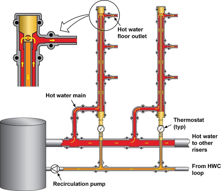
DISCLAIMER

This report was prepared as an account of work sponsored by an agency of the
United States Government. Neither the United States Government nor any agency
thereof, nor Battelle Memorial Institute, nor any of their employees, makes any
warranty, express or implied, or assumes any legal liability or responsibility
for the accuracy, completeness, or usefulness of any information, apparatus,
product, or process disclosed, or represents that its use would not infringe
privately owned rights. Reference herein to any specific commercial product,
process, or service by trade name, trademark, manufacturer, or otherwise does not
necessarily constitute or imply its endorsement, recommendation, or favoring by
the United States Government or any agency thereof, or Battelle Memorial
Institute. The views and opinions of authors expressed herein do not necessarily
state or reflect those of the United States Government or any agency thereof.

            PACIFIC NORTHWEST NATIONAL LABORATORY
                               operated by
                              BATTELLE
                                  for the
              UNITED STATES DEPARTMENT OF ENERGY
                   under Contract DE-AC05-76RL01830

                         Printed in the United States of America

                    Available to DOE and DOE contractors from the
                     Office of Scientific and Technical Information,
                       P.O. Box 62, Oak Ridge, TN 37831-0062;
                                    ph: (865) 576-8401
                                   fax: (865) 576-5728
                             email: reports@adonis.osti.gov

         Available to the public from the National Technical Information Service
                        5301 Shawnee Rd., Alexandria, VA 22312
                                 ph: (800) 553-NTIS (6847)
                  email: orders@ntis.gov
                           Online ordering: http://www.ntis.gov

                                Choose an item.
PNNL-SA-156938

Domestic Hot Water Temperature Maintenance
Technology Review

August 2021

CE Cejudo
AR Davila
K Stoughton

Prepared for
the U.S. Department of Energy
under Contract DE-AC05-76RL01830

Pacific Northwest National Laboratory
Richland, Washington 99354
PNNL-SA-156938

      Contents
      1.0       Overview .........................................................................................................................1
      2.0       Energy and Water Use ....................................................................................................2
                2.1   Understanding Your Building’s Hot Water System ...............................................3
      3.0       Occupant Safety and Comfort .........................................................................................5
      4.0       Hot Water Temperature Maintenance System Options ....................................................6
                4.1        HWTM System Comparison .................................................................................6
                4.2        Traditional Hot Water Recirculation Systems .......................................................6
                           4.2.1        Return Loop Layout ...............................................................................6
                           4.2.2        Balancing Valves ...................................................................................7
                           4.2.3     Pumps ...................................................................................................8
                4.3        Alternative HWTM Systems .................................................................................8
                           4.3.1        Self-Regulating Heat Trace System .......................................................8
                           4.3.2        Point-of-Use System............................................................................10
                           4.3.3        Internal Recirculation System ..............................................................11
                           4.3.4        Flow Splitter System ............................................................................11
                           4.3.5        Demand Recirculation .........................................................................12

      Figures
      Figure 1. Water Loss per Foot of Dead Leg ................................................................................3
      Figure 2. A recirculating hot water system...................................................................................7
      Figure 3. Self-Regulating Heat Trace Cable ................................................................................9
      Figure 4. Self-Regulating Heat Trace System Components ........................................................9
      Figure 5. Instantaneous POU Electric Water Heater (left), Small Tank POU Water Heater
                     (right) .................................................................................................................10
      Figure 6. Internal Recirculation System .....................................................................................11
      Figure 7. Flow Splitter System ..................................................................................................12
      Figure 8. Demand Recirculating System ...................................................................................12

      Tables
      Table 1. Hot Water Delivery Wait Time in Seconds .....................................................................2
      Table 2. Domestic Hot Water Service and Delivery Temperatures ..............................................5
      Table 3. Alternative Systems Comparison to Traditional HWR System .......................................6

Contents                                                                                                                                              iii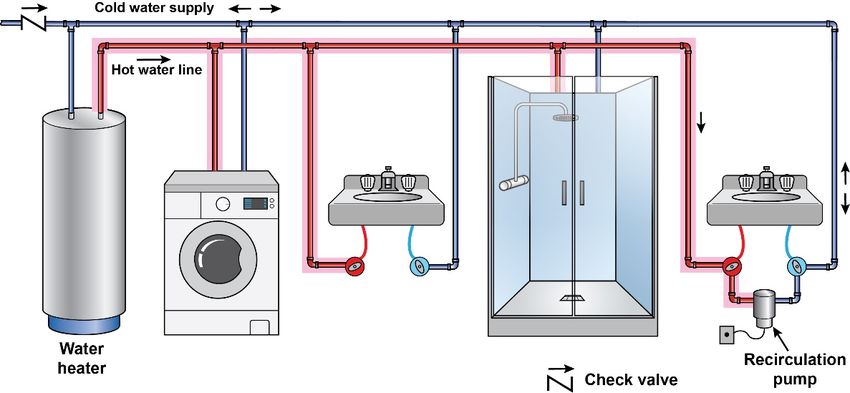
PNNL-SA-156938

      1.0 Overview
      Domestic hot water temperature maintenance (HWTM) is an important topic in facility
      management, and there are often opportunities to optimize systems to achieve energy, water,
      and maintenance savings. The main purpose of a HWTM system is to provide reliable hot water
      at all fixtures with minimal wait time, saving both water and energy. This is done by reducing the
      length of hot water supply piping to the fixture and replacing heat losses during periods of low
      demand.

      This document provides an overview of why the topic         This paper focuses on hot water
      of HWTM is important, how to understand your                temperature maintenance (HWTM)
      building’s system, considerations for occupant comfort,     systems, not domestic hot water
      and comparison of typical and newly available               (DHW) generation systems, which
      technologies. The systems discussed in this report are      are the primary source of heating
      applicable for both new construction and existing           incoming cold water supply.
      buildings.

Overview                                                                                                   1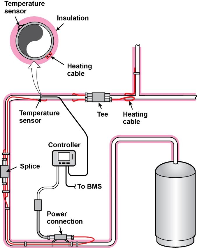
PNNL-SA-156938

      2.0 Energy and Water Use
      All piping in hot water systems is subject to heat transfer to the environment, called standby
      losses. Insulation reduces but does not eliminate standby losses. If standby losses are not
      thoroughly managed, energy and water are wasted while users wait for the desired water
      temperature to flow at the tap. The factors that impact wait time are the fixture flow rate, and the
      length and diameter of the “dead leg” branch (the last section of pipe to a fixture not served by
      the HWTM system).

      According to the American Society of Plumbing Engineers (ASPE) Domestic Water Heating
      Design Manual, 2nd ed, 1 a reasonable wait time for delivery of hot water is 0-10 seconds from
      when the valve is opened. A delay of 11-30 seconds is possibly acceptable, and a delay over 30
      seconds is considered unacceptable. Table 1 illustrates the estimated wait time for a given
      fixture flow rate and typical lengths of dead legs by diameter. For example, a fixture flow rate of
      1.5 gpm (gallons per minute), a dead-leg length of 10 ft, and a pipe diameter of 3/4 in. will have
      an expected wait time of 16 seconds before hot water flows to the fixture at the proper
      temperature.

                                 Table 1. Hot Water Delivery Wait Time in Seconds
              Fixture Flowrate         0.5 gpm             1.5 gpm          2.5 gpm           4.0 gpm
          Length of dead leg        10 ft     25 ft    10 ft     25 ft    10 ft   25 ft    10 ft    25 ft
          ½-in. pipe diameter        25        63*       8        21        5      13       3         8
          ¾-in. pipe diameter       48*       119*      16        40*      10      24       6        15
          *Wait time exceeds acceptable standards

      The cooled hot water sitting in the dead leg branch is lost down the drain before the temperature
      is suitable for use. The cost associated with this wasted water includes the cost of delivering the
      potable water to the building, heating and maintaining the hot water, and the sewerage fees to
      remove the water. Figure 1 illustrates the volume of cooled hot water in a dead-leg segment that
      is lost down the drain during the wait times from Table 1.

      1
       ASPE – American Society of Plumbing Engineers. Domestic Water Heating Design Manual – 2nd
      Edition. Available at https://www.aspe.org/product/domestic-water-heating-design-manual-2nd-edition/.

Energy and Water Use                                                                                           2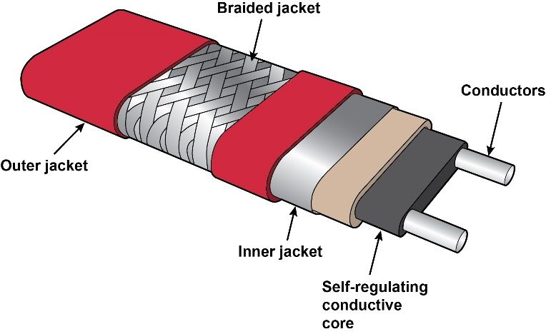
PNNL-SA-156938

                                                Volume of Water Loss in Dead Legs
                                 1.4

                                 1.2
          Water Loss (gallons)

                                  1

                                 0.8

                                 0.6

                                 0.4

                                 0.2

                                  0
                                       1   2      3          4             5     10         20       30   40      50
                                                                  Length of Dead-Leg (ft)

                                                      3/4" Diameter Pipe        1/2" Diameter Pipe

                                               Figure 1. Water Loss per Foot of Dead Leg

      Studies quantifying the energy and water use of DHW systems, including HWTM, are limited.
      Those few available are based on multifamily buildings on the West Coast and the Northeast 1,2,3
      These studies indicate standby losses can be up to 30%-40% of the DHW energy load, which
      itself may be 10%-25% of the total building load. Water savings were not quantified in these
      studies, but the magnitude of savings can be approximated using Table 1 and Figure 1 and
      estimating the length of dead legs in the system.

      This waste of energy and water can be minimized by proper design and installation,
      commissioning, maintenance and operation, and in some cases by adding appropriate retrofit
      solutions for HWTM.

      2.1 Understanding Your Building’s Hot Water System
      A simple way to understand your water and energy savings potential is to consider how much
      water is wasted from taps before hot water arrives. Because energy and water savings are site
      specific, the guidelines below can help estimate the potential savings opportunities at your
      facility.
      1. Measure the time it takes for water at a tap to reach the desired temperature. This should be
         done after a period of no water flow, such as the first use of a sink after an unoccupied
         weekend. Ideally, no fixture should take longer than 0-10 seconds to deliver hot water.

      1
        Heller J, S Oram, G Mugford, M Logsdon, and B Larson. 2017. Multi-Family Hot Water Temperature
      Maintenance Study. Prepared for Bonneville Power Administration. https://ecotope-publications-
      database.ecotope.com/2016_007_MultifamilyTemperatureMaintenanceStudyReport.pdf.
      2
        Ayala GD and D Zobrist. 2012. Best Practices for Efficient Hot Water Distribution in Multifamily
      Buildings. In 2012 ACEEE Summer Study on Energy Efficiency in Buildings.
      https://www.aceee.org/files/proceedings/2012/data/papers/0193-000030.pdf
      3
        Skinner P and G Klein. 2020. Practically Perfect Plumbing In Multifamily. PHCP Pros.
      https://www.phcppros.com/articles/11971-practically-perfect-plumbing-in-multifamily

Energy and Water Use                                                                                                        3
PNNL-SA-156938
2. Identify the flow rates of the fixtures. Showerheads and faucets typically have them listed.
3. Estimate the amount of use the fixture gets. Ask questions like: Do occupants regularly use
this shower? Do many occupants reside nearby that would use this specific sink? Or is it in a
distant bathroom and used rarely?
4. Is the fixture in question far away from a recirculation loop (long dead-leg branch)? The
plumbing plans for the building can help with determining this.
5. Check the recirculation pump. Does it operate 24/7? Is there a timer or thermostatic
controls?
Based on the responses, it’s possible to qualitatively assess the current operation of your DHW
system and consider relatively low-cost solutions for “low-hanging fruit.” The following are some
considerations for simple improvement opportunities.
• Tepid water in a dead-leg section of pipe needs to be flushed before hot water arrives at the
faucet. As such, it should be noted that installing low-flow faucet aerators and showerheads
may increase the hot water delivery time. When showers take long to heat up, users tend to
walk away to let water temper. Installing a shower stop device can limit the amount of water
wasted from this user tendency.
• If a distant fixture sees little use, consider installing small point of use (POU) water heaters
at the fixture, and valving off the hot water loop to reduce the amount of heat loss in pipes
and associated pumping energy. Instantaneous heaters also have the advantage of
significantly reducing time-to-tap.
• It is not always possible to access pipes inside walls, but insulation on all segments of hot
water pipes should be added/repaired wherever possible. A DHW system with good
insulation provides the opportunity to run a recirculation pump less often.
Energy and Water Use 4PNNL-SA-156938
3.0 Occupant Safety and Comfort
Hot water is used in lavatories, showers, kitchens, sinks, tubs, appliances, and more. It provides
a comfortable experience when used for hand washing or bathing. Hot water is known to be
more effective than cold water at removing oils that can harbor bacteria in heavily soiled clothing
or dishes. For these end uses, water needs to be supplied at hotter temperatures; however,
care must be taken to avoid scalding occupants, which can occur in two seconds at 150°F, and
in six seconds at 140°F. Anti-scald devices should be provided for lavatories and showers.
Comfortable temperatures at lavatories and sinks (generally around 105°F) promote longer
hand washing times, which improves hygiene.
Care should be taken to ensure water does not become stagnant for extended periods.
Stagnant water allows free chlorine disinfectant levels to dissipate, which contributes to
pathogen development and can also corrode metal pipes. Additionally, stagnant water at tepid
temperatures (below 120°F) in piping or storage tanks can breed Legionella pneumophila, a
bacterium that causes Legionnaire’s disease when inhaled through spray or mist from a fixture.
As such, DHW systems are subject to several important temperature criteria, and in general
need to:
• Avoid stagnant water conditions
• Maintain water temperatures according to applicable plumbing codes and ASHRAE
guidelines and standards to limit the growth of pathogens such as Legionella
• Provide comfortable temperatures for occupants while avoiding scalding
• Maintain ability to provide hot water for appliances with and without booster heaters
Table 2 shows typical hot water delivery temperatures for different types of fixtures and
appliances.
Table 2. Domestic Hot Water Service and Delivery Temperatures
Recommended Recommended
Minimum Stored Water Delivered Temp to
End Use Temp °F Fixture °F
Showers 140 105-110
Lavatories 140 105-100
Residential Sinks and Dishwashers 140 120
Residential Clothes Washers 140 120
Commercial Clothes Washers 140 140-180
Commercial Sinks 140 140-160
Commercial Dishwashers with Internal Booster 140 140-160
Commercial Dishwashers without Internal Booster 180 180-195
Given the variety of temperatures to be managed based on end uses, it is clear why there can
be conflicting guidance on setting appropriate temperatures for DHW systems. The most
effective and efficient systems often benefit from robust design and operational principles in
order to meet all these criteria. Certain facilities such as hospitals and clinics may have more
stringent requirements per ASHRAE Guideline 12-2000, Minimizing the Risk of Legionellosis
Associated with Building Water Systems.
Occupant Safety and Comfort 5PNNL-SA-156938
4.0 Hot Water Temperature Maintenance System Options
HWTM systems are part of the design of a DHW system. All DHW systems include a primary
heat source and supply piping to the hot water fixtures. Below, find a comparison of common
HWTM systems along with a description of each HWTM system option type.
4.1 HWTM System Comparison
Table 3 ranks the most common alternative HWTM systems compared to a traditional HWR
system for key attributes such as water savings potential and cost. This table is intended to
provide facility managers with important information to understand the impact of existing HWTM
systems to water and energy use, and when evaluating potential options. The table is based on
input from several Pacific Northwest National Laboratory hot water system experts in
engineering design and field surveys. Expand the headings below to find a description of a
traditional HWR system and alternative technologies.
Table 3. Alternative Systems Comparison to Traditional HWR System
Self- Internal
Regulating Point of Recirculation Flow Splitter Demand
Measure Heat Trace Use System System Recirculation
Energy Use* Lower Lower Comparable Comparable Lower
Water Use Lower Lower Comparable Comparable Lower
Operating Costs Lower Lower Comparable Comparable Lower
Installation First
Comparable Lower Higher Higher Lower
Cost
Ease of Retrofit Higher Higher Lower Lower Higher
Improved
Lower Higher Comparable Higher Lower
Legionella Control
* Does not include energy used to heat incoming cold water supply.
4.2 Traditional Hot Water Recirculation Systems
The most common service HWTM system is a “traditional” hot water recirculation (HWR)
system, which moves hot water throughout the system and returns it to the hot water source to
be reheated via a dedicated loop and pump. Because this is the most commonly used system in
use, this section provides information on efficient pipe layout, balancing valves and pumps that
should be considered for optimal design and operation.
4.2.1 Return Loop Layout
The pipe segments in a return loop are classified as:
Hot Water Temperature Maintenance System Options 6PNNL-SA-156938
1. Mains: Sections of hot water or return piping that are connected to the hot water generation
system. These pipes are typically larger than branches or fixture supply pipes.
2. Subloops: Subloops maintain HWR in a zone by connecting to the hot water main with a
balancing valve.
3. Dead-Leg Branches: Piping sections serving a fixture, or bank of fixtures, without a return
to the main distribution system. Dead-leg branches are inevitable but their lengths should be
limited to no more than 50 ft.
An efficient HWR system design has the return loop located as close to the hot water fixture(s)
as possible (Figure 2). This layout reduces the number and length of dead legs, while optimizing
routing of mains and subloops to reduce hot water wait times.
Figure 2. A recirculating hot water system
4.2.2 Balancing Valves
Because water flows through the path of least resistance, balancing valves are used to throttle
hot water in the most remote segment of the return loop to balance out heat losses throughout
the system. Three types of valves are typical in HWR systems: pressure dependent, fixed flow,
and thermostatic valves. Recognizing the types of valves installed in your facility can help with
troubleshooting and maintaining a system.
Pressure Dependent - The most common type in traditional HWR systems, this type maintains
a set pressure across the valve. These valves are field adjustable and require an iterative
Hot Water Temperature Maintenance System Options 7PNNL-SA-156938
process to correctly balance the entire recirculation system. They typically have a minimum flow
rate of 0.5 gpm.
Fixed Flow - This valve type is factory set to a specified flowrate. The valve has replaceable
internal components for easy maintenance. They are prone to clogging due to the small orifice
design. They are available down to a minimum flow rate of 0.33 gpm.
Thermostatic - A dynamic valve that opens automatically based on a set temperature at the
connection to the return loop. While more expensive upfront, they eliminate the need for field
adjustment, saving installation labor. The minimum flowrate is 0.1 gpm, which can better match
the heat loss calculations to optimize pump sizing.
4.2.3 Pumps
Hot water circulation pumps serve an important role in a traditional HWR system by moving
cooled hot water back to the water heater. This recirculation maintains the hot water supply in
the distribution piping up to the desired temperature under conditions of low or no demand. As
the HWR system is essentially a closed loop in conditions of low or no demand, the pump head
is determined by the friction losses in the return pipe network. The pump flow capacity is a
function of (a) the heat lost through insulation over a period of time and (b) the acceptable
temperature drop at the balancing valves. Oversized pumps can induce high flow velocities that
over time will erode the pipe wall, causing pinhole leaks that may be difficult to isolate and
repair.
HWR pumps are typically small, in-line mounted, and constructed of bronze or stainless steel for
corrosion resistance and to comply with lead-free requirements for potable water systems. They
can operate at constant or variable speeds, with newer electronically commutated motor models
having onboard controls to “learn” user demand patterns. Traditional HWR systems are typically
controlled from a temperature sensor (called an aquastat) located upstream of the circulation
pump. Some designs activate the circulation pump on a timer or a push button at the most
remote fixture.
4.3 Alternative HWTM Systems
The two most common alternatives to a traditional HWR system are self-regulating heat trace
(heat trace) and point-of-use (POU) systems. Recently, two innovative alternatives to traditional
HWR have come on the North American market: internal recirculation and flow splitter systems.
A hot water system design may incorporate a combination of these HWTM systems based on
the building’s layout to minimize wait times and optimize water and energy savings. Any well,
maintained and operated HWTM system will safely deliver hot water within a maximum wait
period to save water and energy.
4.3.1 Self-Regulating Heat Trace System
An HWTM heat trace system is a series of cables installed along the hot water piping to replace
standby losses (Figure 3). This system consists of specialized self-regulating cables, connection
kits, and custom electronic controls (Figure 4). The cable is installed directly on the hot water
supply pipes underneath the insulation, eliminating the need for a traditional recirculation
system. The cable controls are set to the desired temperature to be maintained, and the cable
adjusts its power output to replace heat loss through the insulation during periods of low
Hot Water Temperature Maintenance System Options 8PNNL-SA-156938
demand. It is not intended to replace the primary domestic hot water generation system or to
provide freeze protection.
A self-regulating heat trace system can use less energy than a traditional HWR system as it
only heats the section of hot water pipe that needs it and does not require pumping hot water
through the whole system in two sets of pipes.
If being installed as a retrofit, careful coordination with the building’s electrical system is
required during design to ensure required wiring, ground fault circuit interrupter breakers, local
disconnects, and other associated components are provided and installed per the
manufacturers’ instructions for components in contact with potable water.
Figure 3. Self-Regulating Heat Trace Cable
Figure 4. Self-Regulating Heat Trace System Components
Hot Water Temperature Maintenance System Options 9PNNL-SA-156938
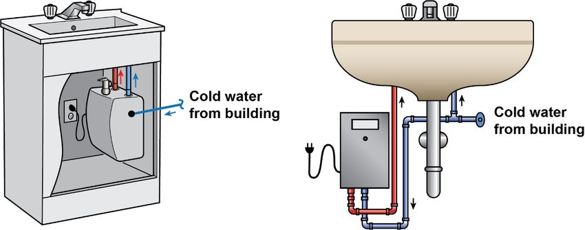
4.3.2 Point-of-Use System
Small POU systems are supplied by a cold water connection only to eliminate the need for hot
water temperature maintenance. Options are typically between instantaneous water heaters and
small storage tanks (2-10 gallons) (Figure 5). Instantaneous water heaters powered by
electricity draw larger current than a small storage tank type model. Instantaneous gas water
heaters are typically larger and applicable to high-volume demands such as showers,
commercial kitchens and laundry. An inefficient architectural layout may be better served with
several smaller, centralized DHW systems (generation and recirculation) for higher-demand
fixture banks (showers, commercial kitchens) and distributed POU water heaters at remote
fixtures.
Figure 5. Instantaneous POU Electric Water Heater (left), Small Tank POU Water Heater (right)
Hot Water Temperature Maintenance System Options 10PNNL-SA-156938
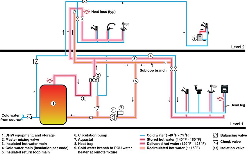
4.3.3 Internal Recirculation System
This “pipe in a pipe” system has the recirculation loop main installed inside the hot water supply
riser, eliminating a separate insulated return riser and replacing heat losses via the hot water
supply temperature (Figure 6). It is best suited for multi-story buildings with higher hot water
demands as the hot water riser pipe size needs to account for the internal return pipe diameter.
As in a traditional HWR system, care must be taken to reduce the quantity and length of dead
legs to reduce delay in hot water delivery time.
Figure 6. Internal Recirculation System
4.3.4 Flow Splitter System
A flow splitter valve has an internal Venturi nozzle which creates a small pressure differential to
direct water flow through a branch subloop (Figure 7). The valve maintains a minimum open
position, allowing full flow through the main loop at peak demand conditions. During low
demand, the flow is directed through the subloop, thus reducing stagnation.
A flow splitter system requires careful planning of the piping network to create branch subloops
to the hot water fixtures, reducing the size of (and possible need for) a traditional HWR system.
Use of this system is best suited for new construction and retrofit of facilities that may encounter
stagnant water due to low occupancy, or that require a high level of hygiene such as hospitals
and clinics.
Hot Water Temperature Maintenance System Options 11PNNL-SA-156938
Figure 7. Flow Splitter System
4.3.5 Demand Recirculation
Small “demand” recirculation systems circulate water to the furthest fixture when called, either
by an occupancy sensor or push button (Figure 8). Although allowed by recent code updates,
these systems are not recommended for commercial applications as they connect the hot water
supply pipe to a small pump at the furthest fixture, allowing tepid water to flow into the domestic
cold water supply pipes. This configuration could contribute to Legionella growth, introduction of
dissolved metals from the hot water heater into the cold water supply, and potential scalding if
thermostats are not correctly set.
Figure 8. Demand Recirculating System
Hot Water Temperature Maintenance System Options 12PNNL-SA-156938 Pacific Northwest National Laboratory 902 Battelle Boulevard P.O. Box 999 Richland, WA 99354 1-888-375-PNNL (7665) www.pnnl.gov
You can also read