Doppler Radar-Based Non-Contact Health Monitoring for Obstructive Sleep Apnea Diagnosis: A Comprehensive Review - MDPI
←
→
Page content transcription
If your browser does not render page correctly, please read the page content below
big data and
          cognitive computing

Review
Doppler Radar-Based Non-Contact Health
Monitoring for Obstructive Sleep Apnea Diagnosis:
A Comprehensive Review
Vinh Phuc Tran 1,2, * , Adel Ali Al-Jumaily 1 and Syed Mohammed Shamsul Islam 3,4
 1   Centre for Health Technologies, Faculty of Engineering & Information Technology (FEIT), University of
     Technology, Sydney (UTS), Ultimo NSW 2007, Australia; Adel.Al-Jumaily@uts.edu.au
 2   Digital Health Technology, Respiratory Care Solutions, ResMed Ltd., Bella Vista NSW 2153, Australia
 3   The Discipline of Computing and Security, School of Science, Edith Cowan University (ECU), Joondalup
     WA 6027, Australia; Syed.Islam@ecu.edu.au or Syed.Islam@uwa.edu.au
 4   School of Computer Science and Software Engineering (Adjunct), University of Western Australia (UWA),
     Crawley WA 6009, Australia
 *   Correspondence: Vinh.P.Tran-1@student.uts.edu.au or Vinh.Tran@resmed.com.au

 Received: 2 December 2018; Accepted: 24 December 2018; Published: 1 January 2019

 Abstract: Today’s rapid growth of elderly populations and aging problems coupled with the
 prevalence of obstructive sleep apnea (OSA) and other health related issues have affected many
 aspects of society. This has led to high demands for a more robust healthcare monitoring, diagnosing
 and treatments facilities. In particular to Sleep Medicine, sleep has a key role to play in both physical
 and mental health. The quality and duration of sleep have a direct and significant impact on people’s
 learning, memory, metabolism, weight, safety, mood, cardio-vascular health, diseases, and immune
 system function. The gold-standard for OSA diagnosis is the overnight sleep monitoring system
 using polysomnography (PSG). However, despite the quality and reliability of the PSG system, it is
 not well suited for long-term continuous usage due to limited mobility as well as causing possible
 irritation, distress, and discomfort to patients during the monitoring process. These limitations
 have led to stronger demands for non-contact sleep monitoring systems. The aim of this paper is to
 provide a comprehensive review of the current state of non-contact Doppler radar sleep monitoring
 technology and provide an outline of current challenges and make recommendations on future
 research directions to practically realize and commercialize the technology for everyday usage.

 Keywords: sleep monitoring; patient monitoring; non-contact monitoring; vital signs monitoring;
 health monitoring; obstructive sleep apnea; sleep; sensors; Doppler radar; non-contact vital signs;
 respiration; cardiac activity; pressure; Tidal volume; sleep wake pattern; apnea-hypopnea index;
 Cheyne-Stokes respiration; computer vision; machine learning; body orientations; body movements

1. Introduction
     Obstructive sleep apnea (OSA) is a common and potentially lethal sleep disorder affecting at least
4% of adult males and 2% of adult females world-wide [1]. Statistics published in 2013 reported that
the prevalence of OSA had increased between 10–17% for adult males and 3–9% for adult females in
the United States of America (USA) [2].
     OSA is the cessation of airflow due to the collapse of the upper airway during sleep and can
occur at any age from infancy to old age. Statistics have shown that the male to female ratio is about
2:1 and probably affects prepubertal males and females at equal rate [3]. Evidence has indicated that
OSA is associated with ischemic heart disease, increased prevalence of stroke, coronary artery disease,
atrial fibrillation (AF), chronic heart failure (CHF), and cardiac sudden death [4]. In addition, OSA

Big Data Cogn. Comput. 2019, 3, 3; doi:10.3390/bdcc3010003                      www.mdpi.com/journal/bdcc
Big Data Cogn. Comput. 2019, 3, 3 2 of 21
may also be associated with increase cholesterol, hypertension [5], type 2 diabetes [6,7], and cancer
mortality [8]. OSA can also lead to oxygen desaturations, oxidative stress, blood pressure, heart rate
changes, and interrupted sleep [9,10].
The gold-standard for OSA diagnosis is the overnight sleep monitoring system using
polysomnography (PSG), which records the electric potentials of the brain, heart, eye movement,
muscle activity, respiratory effort, airflow, oxygen saturation, and leg movements throughout the
night [11]. Despite the quality and reliability of the PSG system, it is not well suited for long-term
continuous monitoring usage [12] due to limited mobility as well as causing possible irritation, distress,
and discomfort to patients during the monitoring process [13]. These limitations have led to stronger
demands for non-contact sleep monitoring systems.
Non-contact biosensor such as microwave Doppler radar for physiological vital signs monitoring
was discovered in the 1970s. Literature has been published regarding non-contact assessments
of respiratory and heart rates. However, the tendencies of reported achievements are based on
“stationary” and “direct-facing” subject measurements, which is not an ideal scenario for the complexity
of sleep environment.
As documented in literature, the issue with getting an accurate reading from a non-contact
monitoring device is due to background clutter, phase-nulling or null point, DC offsets, motion
artefacts and electromagnetic interferences [13]. In addition, for continuous sleep monitoring in
particular, the challenges are in the complexity of the sleep environment, noises associated with the
unpredictability of body movements, body orientations, changes in sleeping posture, multi-subjects
cancellation, undesired harmonics, and intermodulation [14,15].
There have also been numerous reviews, comparison studies [16–19], and smart systems
designs [20,21] regarding unobtrusive [22], nonintrusive [23], and non-contact physiological vital
signs monitoring for sleep monitoring. However, a comprehensive review of the non-contact Doppler
radar for health monitoring for OSA diagnosis has been limited. This is the primary motivation of this
review paper.
The aim of this paper is to provide a comprehensive review on the current state of non-contact
Doppler radar for sleep monitoring technology. This includes a review of the system theoretical
fundamentals, signal processing methodologies, techniques, achievements and challenges. In addition,
this paper also discusses potential future research directions, as well as, potential applications of this
technology in the daily life.
The topic used for the literature search is “sleep monitoring using non-contact Doppler radar.”
The searching of relevant literature ranges across multiple databases and online journals; including
the University of Technology, Sydney (UTS, Ultimo NSW 2007, Australia) databases, PubMed,
ScienceDirect, IEEE Xplore, and many more. The inclusions and/or exclusions of certain articles are
based on its relevance to the field of non-contact Doppler radar physiological vital signs estimations
and sleep indices predictions.
This paper is organized as follows: Section 2 describes the topologies and architectures of the
non-contact Doppler radar systems. Section 3 describes the fundamentals principles of the non-contact
Doppler radar systems. Section 4 outlines the sources of noises associated with the non-contact Doppler
radar systems. Section 5 describes the signal processing techniques, whilst Section 6 categories the
techniques of non-contact Doppler radar physiological vital signs estimations and sleep monitoring.
Section 7 provides a brief outline of the ultra-wide band (UWB) Doppler radar systems and its usage
in the vital signs estimations. Section 8 outlines current challenges and makes recommendations for
future research directions. Finally, Section 9 concludes the work presented in this paper.Big Data Cogn. Comput. 2019, 3, 3 3 of 21
Big Data Cogn. Comput. 2019, 3 FOR PEER REVIEW 3 of 20
Big Data Cogn. Comput. 2019, 3 FOR PEER REVIEW 3 of 20
2. Non-Contact Doppler Radar Architecture
Heterodyning is a radio signal processing technique in which new frequencies are created by
Heterodyning
combining or mixing
2.1. Heterodyne
is a radio
of two
versus Homodyne
signal processingThese
frequencies.
Topology
technique
new infrequencies
which neware frequencies are created by
called “Heterodynes.”
combining
Heterodyneor mixing of
transceiver two frequencies.
usually These new
contains a separate local frequencies
oscillator (LO) areoscillating
called “Heterodynes.”
at the radar’s
HeterodyneHeterodyning
transceiver is a radio
usually signal
contains processing
a separatetechnique
local in which
oscillator new
(LO) frequencies
oscillating are
at created
the radar’s
operating frequency (RF) to radiate and transmit signal (Tx). The received signal (Rx) is filtered by a
by combining or mixing of two frequencies. These new frequencies are called “Heterodynes.”
operating
band-pass frequency
filter (BPF)(RF)andto radiate
mixed and
withtransmit
another signal (Tx). The
separate LO received
oscillating signal
at (Rx) is filtered
different by a
frequency
Heterodyne transceiver usually contains a separate local oscillator (LO) oscillating at the radar’s
band-pass
compared filter
to the (BPF)
RF. Thisand mixedthat with another separate LO oscillating a at different frequency
operating frequency (RF) means
to radiate andthe mixedsignal
transmit signal is The
(Tx). modulated
received onsignal non-zero intermediate
(Rx) is filtered by a
compared
frequency to the
(IF)
band-pass filterRF.
rather(BPF)This
than means
andbeing that another
mixedconverted
with the mixed
directly signal
separate to LO is modulated
baseband. The
oscillating on asignal
mixed
at different non-zero intermediate
is also
frequency filtered by
compared
frequency
another
to the (IF)followed
BPF,
RF. rather
This meansthan abeing
bythat low converted
noise
the mixed signaldirectly
amplifier to baseband.
(LNA),
is modulated and The mixed
on demodulated
a non-zero signalor
directly
intermediate is mixed
also filtered
frequency (IF) by
down to
another BPF,
rather before
baseband followed
than being by a low noise
converted directly
demodulation amplifier
to baseband.
[13,18,24]. (LNA), and
The mixed
An illustration demodulated
signal
of the directly
is also filtered
heterodyne or mixed
by another
transceiver down
BPF, is
topology to
baseband before
followed by
shown in Figure 1. a demodulation
low noise [13,18,24].
amplifier (LNA), An
and illustration
demodulated of the
directly heterodyne
or mixed down transceiver
to baseband topology
before is
shown in Figure 1.[13,18,24]. An illustration of the heterodyne transceiver topology is shown in Figure 1.
demodulation
Figure 1. Heterodyne transceiver topology.
Figure
Figure1.1.Heterodyne
Heterodyne transceiver topology.
transceiver topology.
The advantage of heterodyne topology is that different received frequencies can be converted to
The advantage of heterodynetopology
topologyisis that
that different
different received frequencies cancan be converted to to
the sameadvantage
The IF prior to of theheterodyne
amplification or filtering processes and received
the IFfrequencies be converted
is also at a considerably lower
the same IF prior to the amplification or filtering processes and the IF is also at a considerably lower
the same
frequency IF prior
than to
thethethe
RF. amplification or filtering processes and the IF is also at a considerably lower
frequency than RF.However,
However, aa major
majordisadvantage
disadvantage of of heterodyne
heterodyne topology
topology is the is thenumber
high high number
of
frequency
of circuitry than the RF. However, a major disadvantage of heterodyne topology is the high number
circuitrycomponents
components and andpassives
passives[13,18,24].
[13,18,24].
of circuitry
Homodyne components
Homodyne is often and
is often
passives [13,18,24].
referred
referredtotoas as direct-conversion receiver(DCR),
direct-conversion receiver (DCR), synchrodyne,
synchrodyne, or zero-IF
or zero-IF
Homodyne
receiver. The The
receiver. is
receivedoften
received referred
signal is mixed
signal to as
with
is mixed direct-conversion
a LO
with at the
a LO RF, RF,
at the receiver
i.e.,i.e.,
the the
same (DCR), synchrodyne,
frequency
same frequency as its or
carrier,
as its zero-IF
which
carrier,
receiver.
converts The
whichthe received
signal to
converts signal
thebaseband.is mixed with
The baseband
signal to baseband. a LO at the RF, i.e.,
signal is filtered
The baseband the same
signal isusing frequency
baseband
filtered as its carrier,
BPF andBPF
using baseband which
is amplified
and
converts
using the signal
is baseband
amplified LNA to baseband.
using baseband
prior The baseband
LNA
to baseband prior signal isprocess
to baseband
demodulator filtered or
demodulator using baseband
process
digitizer BPF and
or digitizer
[13,18,24]. isillustration
amplified
[13,18,24].
An
usingAn
of the baseband
illustration
homodyne LNA prior
of the totopology
homodyne
transceiver baseband is demodulator
transceiver
giventopology isprocess
in Figure 2. inor
given digitizer
Figure 2. [13,18,24]. An illustration
of the homodyne transceiver topology is given in Figure 2.
Figure
Figure2.2.Homodyne transceivertopology.
Homodyne transceiver topology.
Figure 2. Homodyne transceiver topology.
The advantage of homodyne topology is the simplification of the basic circuit complexity.
However,advantage
The of homodyne
a major disadvantage of topology
homodyneistopology
the simplification of the
is the amount basic
of DC circuit
offsets complexity.
introduced by
However, a major disadvantage of homodyne topology is the amount
the system, which can cause saturation for digitizer process [13,18,24]. of DC offsets introduced by
the system, which can cause saturation for digitizer process [13,18,24].
2.2. Continuous-Wave versus Pulsed-Wave Architecture
2.2. Continuous-Wave versus Pulsed-Wave Architecture
The continuous-wave (CW) radar system continuously transmits and receives narrowBig Data Cogn. Comput. 2019, 3, 3 4 of 21
The advantage of homodyne topology is the simplification of the basic circuit complexity.
However, a major disadvantage of homodyne topology is the amount of DC offsets introduced
by the system, which can cause saturation for digitizer process [13,18,24].
2.2. Continuous-Wave versus Pulsed-Wave Architecture
The continuous-wave (CW) radar system continuously transmits and receives narrow bandwidth
signal.
Big CWComput.
Data Cogn. radar 2019,
consists
3 FORof a signal
PEER REVIEW source that can be used for both transmitting and receiving. 4 of 20
Either heterodyne or homodyne topology can be used in CW radar system. However, homodyne
topology istopology
homodyne more commonly used in CW.
is more commonly usedThis
in radar
CW. This system
radarhassystem
the advantages of simplicity,
has the advantages of
potential of
simplicity, minimalofspread
potential minimal in spread
the transmitted spectrum,spectrum,
in the transmitted and unambiguously
and unambiguously measuremeasure
velocity
of targets.
velocity In addition,
of targets. CW radar
In addition, CWsimplifies the filters
radar simplifies the at eachatstage
filters eachof the of
stage receiver, and the
the receiver, andsignal
the
processing
signal is seemingly
processing straightforward
is seemingly if velocity
straightforward or displacement
if velocity information
or displacement is targeted.
information However,
is targeted.
a disadvantage
However, of the CW of
a disadvantage radar system
the CW is the
radar inability
system is thetoinability
separateto reflections
separate temporally, causing DC
reflections temporally,
offsets and low-frequency noises to be introduced in the received
causing DC offsets and low-frequency noises to be introduced in the received signal [25].signal [25].
A pulsed-wave (PW)
A (PW)radarradarsystem
system requires
requiresa switch
a switchto pulse the transmitting
to pulse the transmittingand receiving signals
and receiving
and hasand
signals a wider
has abandwidth.
wider bandwidth.The advantage of PW radar
The advantage of PWis radar
its ability
is itstoability
instantaneously measure
to instantaneously
target range,
measure target temporally separate transmitter
range, temporally leakages, and
separate transmitter strongand
leakages, short-range echoes from
strong short-range the weaker
echoes from
echoes
the of long-range
weaker echoes of targets.
long-range However,
targets.a However,
disadvantage of the PW radar
a disadvantage of the system is thesystem
PW radar ambiguityis thein
both range and velocity measurements. In non-contact physiological
ambiguity in both range and velocity measurements. In non-contact physiological vital signs vital signs monitoring, the target
is typically at
monitoring, thethe sameisortypically
target shorter at range than the
the same nearest range
or shorter clutter;than
therefore, the PW
the nearest radartherefore,
clutter; advantage theis
limited
PW radarto advantage
the elimination of leakage.
is limited to the Since range measurements
elimination of leakage. Since does not measurements
range aid in physiological
does motions
not aid
monitoring,
in physiological the motions
increasedmonitoring,
complexitythe of PW radar over
increased CW radar
complexity doesradar
of PW not result
over CW in a radar
commensurate
does not
increase
result in aincommensurate
benefits [25]. increase in benefits [25].
2.3.Single
2.3. Singleversus
versusQuadrature
QuadratureArchitecture
Architecture
TheDoppler
The Dopplerradar
radartransceivers
transceiverscan
canbebebuilt
builtbased
basedon onaasingle-channel
single-channelor oraaquadrature
quadraturedesign.
design.
Theperformance
The performanceofofsingle-channel
single-channel is known
is known to sensitive
to be be sensitive
to thetoposition
the position
of the of the targets
targets and, in and,
the
in the worst case of null-point, produced virtually no phase-modulated signal
worst case of null-point, produced virtually no phase-modulated signal for the estimation for the estimation
of
of physiological
physiological motions.
motions. TheThe quadrature
quadrature transceiver
transceiver is mainly
is mainly usedused to mitigate
to mitigate thethe null-point
null-point issue
issue in
in single-channel transceiver by selecting the better of the quadrature, i.e., I-channel
single-channel transceiver by selecting the better of the quadrature, i.e., I-channel (in-phase) or Q-(in-phase) or
Q-channel (90 ◦ out-of-phases) for optimum signal demodulation [13,24,26]. The illustrations of the
channel (90° out-of-phases) for optimum signal demodulation [13,24,26]. The illustrations of the
single-channeland
single-channel andquadrature
quadrature designs
designs are
are shown
shown inin Figure
Figure 3a,b.
3a,b.
(a) (b)
Figure
Figure3.3.(a)
(a)Single-channel
Single-channelarchitecture;
architecture;(b)
(b)Quadrature
Quadraturearchitecture.
architecture.
3.Non-Contact
3. Non-ContactDoppler
DopplerRadar
RadarPrinciple
Principle
Dopplerradar
Doppler radarfor
forphysiological
physiologicalvital
vitalsigns
signsmonitoring
monitoring was
was discovered
discovered in in
thethe 1970s.
1970s. TheThe
useuse
of
of Doppler
Doppler radar
radar was demonstrated
was demonstrated for detection
for detection of respiratory
of respiratory rateand
rate in 1975 in heart
1975 rate
and in
heart
1979.rate in
Since
the 1980s, the use of pulsed-wave (PW), continuous-wave (CW), frequency-modulated continuous-
wave (FMCW), Linear-Frequency-Modulated Continuous-Wave (LFMCW), and ultra-wide band
(UWB) radars have also been explored for physiological sensing [25,27–31].
The basic principle of Doppler radar is to transmit a microwave signal towards a target. The
transmitted frequency of the microwave signal is usually within the unlicensed, not unregulatedBig Data Cogn. Comput. 2019, 3, 3 5 of 21
1979. Since the 1980s, the use of pulsed-wave (PW), continuous-wave (CW), frequency-modulated
continuous-wave (FMCW), Linear-Frequency-Modulated Continuous-Wave (LFMCW), and ultra-wide
band (UWB) radars have also been explored for physiological sensing [25,27–31].
The basic principle of Doppler radar is to transmit a microwave signal towards a target. The transmitted
frequency of the microwave signal is usually within the unlicensed, not unregulated Industrial,
Scientific, and Medical (ISM) radio bands, e.g., 5.8 GHz, 10 GHz, or 24 GHz. The phase-modulated of
the backscattered signal is then measured to estimate the periodic motions between the target and the
source of transmission. This technology utilized the principle known as the “Doppler Effect.”
The Doppler Effect occurs when there is a shift in the frequency of the signal, either the transmitted
or echo signal, due to relative motion between the transmitter and the receiver. In other words,
when the target has a time-varying position with a net zero velocity, the echo signal is phase-modulated
proportionally to the target variation [27,32,33].
In a general case, the Doppler shift in frequency can be expressed as
2f 2v(t)
f d (t) = v(t) = (1)
c λ
The time-varying phase shift proportional to the displacement can be expressed as
2f 4πx (t)
Φr ( t ) = 2πx (t) = (2)
c λ
The transmitting (T(t)) and received signal (R(t)) can be represented as
T (t) = A T cos(2π f t + ∅(t)) (3)
4πd0 4πx (t) 2d
R(t) ≈ A R cos 2π f t − − +∅ t− 0 +θ (4)
λ λ c
4πd0
θ= + θ0 (5)
λ
In the case of physiological vital signs monitoring, the target object is usually the subject’s chest
or abdominal region. The echo signal is then demodulated in the receiver to obtain information
regarding the subject’s chest or abdominal movements. Typically, the movements contain information
for both respiratory and heart rates [27,32,33]. It has also been reported that abdominal movements
cause stronger Doppler shift due to higher amplitude and deeper displacement compared to chest
movements [32].
The demodulated baseband quadrature outputs I and Q channels are generally expressed as
4πd0 4πx (t) 4πy(t)
I (t) = VI + A I cos θ0 + + + + ∆φ(t) (6)
λ λ λ
4πd0 4πx (t) 4πy(t)
Q(t) = VQ + AQ sin θ0 + + + + ∆φ(t) (7)
λ λ λ
2d0
∆φ(t) = φ(t) − φ t − (8)
c
where ‘VI ’ & ‘VQ ’ are the DC offsets of the channels and ‘AI ’ & ‘AQ ’ are the amplitude gain constants
of the channels. ‘θ 0 ’ is the initial constant phase-shift of the system in radian. ‘λ’ is the wave length,
which equal the speed of light ‘c’ divided by the radar operating frequency in Hertz. ‘d0 ’ is the initial
distant between the radar and the subject’s chest or abdomen in meter. ‘φ’ is the phase noise of
the system oscillation in radian. ‘x(t)’ is the function of respiratory that causes changes in the chest
displacement in meter. ‘y(t)’ is the function of heart that causes changes in the chest displacement in
meter.Big Data Cogn. Comput. 2019, 3, 3 6 of 21
Typically, Doppler radar is designed for measuring velocity of moving targets and therefore the
scope of its applications are more restricted. However, it is not limited to respiratory and/or cardiac
activity monitoring in a single subject [34]. The information for both respiratory and heart rates can
be extracted from the phase-modulated by the time varying physiological periodic movement of the
chest-wall. Nevertheless, such physiological motions are elastic, deformable with clothing which can
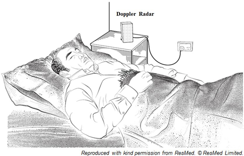
create significant noise issue and adversely affecting the sensitivity of the system [32]. An illustration
of the
Big Datanon-contact Doppler
Cogn. Comput. 2019, 3 FORradar setup in a sleep laboratory or at home is shown in Figure 4. 6 of 20
PEER REVIEW
Figure
Figure 4.
4. Non-contact
Non-contactDoppler
Dopplerradar
radar setup
setup in
in aa sleep
sleep laboratory
laboratory or
or at
at home.
home.
The
The physiological
physiological parameters
parameters and
and sleep
sleep indices
indices which
which have
have been
been demonstrated
demonstrated feasible
feasible in
in
estimation
estimation and/or
and/orprediction
predictionusing
usingnon-contact
non-contactDoppler
Dopplerradar
radarisisshown
shownin
inTable
Table 1.
1.
Table
Table 1. Feasibleparameters
1. Feasible parameters that
that can
can be
be estimated
estimated using
using non-contact
non-contact Doppler
Doppler radar.
radar.
Physiological
Physiological Parameters
Parameters Reference
Reference
Respiratory rate [15,35–40]
Respiratory rate [15,35–40]
Heart rate
Heart rate [14,15,38–40]
[14,15,38–40]
Heart rate variability
Heart rate variability [41][41]
Pulse pressure pressure
Pulse [42][42]
Intrapulmonary
Intrapulmonary pressure pressure [43][43]
Tidal volume
Tidal volume [43–45]
[43–45]
Sleep/wake pattern pattern
Sleep/wake [12,46]
[12,46]
Apnea-hypopnea index index
Apnea-hypopnea [17,47,48]
[17,47,48]
Cheyne-Stokes Respiration
Cheyne-Stokes Respiration [49][49]
Body orientations [50,51]
Body orientations [50,51]
The application
The application ofof Ultra-Wide
Ultra-Wide BandBand (UWB)
(UWB) radars,
radars, utilizing
utilizing the
the “Doppler
“Doppler Effect”
Effect” principle
principle forfor
sensing physiological
sensing physiological vital
vital signs,
signs, has
has also
also been
been reported
reported in
in the
the literature.
literature. Researches
Researchesinin the
the field
field of
of
UWB radars
UWB radars mainly
mainly focus
focus on
on through-wall
through-walllife-signs
life-signsdetection
detectiontargeting
targetingrespiratory
respiratoryand
andheart
heartrates.
rates.
The most challenging
The challengingtask
taskisisthe
theregistration
registrationof of
respiration activity
respiration of an
activity ofunconscious person.
an unconscious The other
person. The
focus is aimed at sensing some key physiological bio-markers of astronauts during
other focus is aimed at sensing some key physiological bio-markers of astronauts during intra-intra-vehicular and
extra-vehicular
vehicular activities [52,53].
and extra-vehicular activities [52,53].
4. Sources
4. Sources of
of Noise
Noise in
in Non-Contact
Non-Contact Doppler
Doppler Radar
Radar
4.1. Clutter and DC Offset
4.1. Clutter and DC Offset
In a radar system, clutters are generally echoes from all objects other than the target. Clutter
In a radar system, clutters are generally echoes from all objects other than the target. Clutter
detected at the receiver is commonly in the form of a single-tone component of the same frequency
detected at the receiver is commonly in the form of a single-tone component of the same frequency
as the local oscillator (LO), however, with a different phase offset. The constant phase-shift is the
as the local oscillator (LO), however, with a different phase offset. The constant phase-shift is the
function of the surface reflectivity and the size of the stationary portion of the target. When clutters
are mixed with the LO, it will result in a DC offset in the baseband signal, and it is therefore difficult
to separate in the frequency domain. If there is a significant DC component present at the signal
output, the output is no longer linearly proportional to the displacement [54,55]. As a result, DC offsetBig Data Cogn. Comput. 2019, 3, 3 7 of 21
function of the surface reflectivity and the size of the stationary portion of the target. When clutters are
mixed with the LO, it will result in a DC offset in the baseband signal, and it is therefore difficult to
separate in the frequency domain. If there is a significant DC component present at the signal output,
the output is no longer linearly proportional to the displacement [54,55]. As a result, DC offset can
saturate and desensitize the receiver in conventional CW radar system, and this is a critical issue [56].
4.2. Phase-Nulling or Null-Point
In a Doppler radar system, the most important limitation in measuring periodic motions such as
respiratory and heart rates, is the presence of phase-nulling or null-point. The null-point occur when
the received signal is either in-phase or 180◦ out-of-phases compared to the local oscillator [33].
The null-point occurs with the target’s distance every quarter of the radar transmitted signal
wave-length (λ/4), and in the worst case produced virtually no phase-modulated signal for the
estimation of physiological motions [26,33,56].
4.3. Others Sources of Noise
Besides clutters, other issues such as DC offsets, phase-nulling contributions, motions artefacts
and electromagnetic interferences are also posing as challenges to the signal processing of Doppler
radar signals [13,57]. Another major challenge in sleep monitoring application is the noise associated
with unpredictable body movements, body orientations, changes in sleeping posture, multi-subjects
cancellation, undesired harmonics and intermodulation [14,15,39].
5. Non-Contact Doppler Radar Signal Processing
It has been decades since the first observation of non-contact Doppler radar in measuring
physiological motions such as respiratory and heart rates. However, to date, a complete understanding
of the mechanism and causes of the observed modulations, frequencies penetrations and body
electromagnetic radiation absorptions are not yet fully achieved.
There has been a number of attempts either in the form of experimental or simulation to investigate
the contributions of blood perfusion, internal body organ movements, body surface movement,
and black-body radiation (due to temperature variations) to the phase-modulated of the received
signal [58]. However, the most dominating theory on the cause of observed modulations is still
believed to be the small periodic movements of the chest wall (due to respiratory and heart motions)
resulting in a small phase changes in the received signal.
Single and multiple Doppler radar systems have also been explored for physiological vital signs
estimations. Advances in hardware circuitry design, antenna exploratory, signal processing techniques,
and classification algorithms have also been explored. However, the main challenges in using Doppler
radar systems for physiological measurement is still the analysis and processing of the received signal
data [59].
5.1. Clutter and DC Offset Cancellation
Earlier work on the Doppler radar system used a single antenna with a circulator to isolate
the transmitting and receiving paths [60], however a major disadvantage in using a circular was
self-mixing, which translate to DC offsets on the output signal [55]. Dual-antennas with separated
transmit and receive paths have also been explored with the advantage of reduced DC offsets [26,61].
Low-pass filters, high-pass filters, notch filters, and complex digital signal processing algorithms
have also been reported for noise filtering and DC offsets elimination [26,27,33,61–63]. The reported
filters are types of Sallen-Key [61,64–66], Elliptic [62,67], Butterworth, and RC passive [33,55,59,68]
filters. Phase and Self-Injection-Locked (PSIL) oscillator with dual-tuning voltage-controlled oscillator
has also been reported to achieve high signal-to-noise ratio [56]. Filtering at signal processing level,
including Finite Impulse Response (FIR) with Kaiser window [36,61,69], Infinite Impulse Response
(IIR) [29], and Savitzky-Golay Polynomial Least Squares (SG) [32] filters have also been proposed.Big Data Cogn. Comput. 2019, 3, 3 8 of 21
Other phase-modulation methods have also been proposed to address DC offset. These include
using arctangent demodulation technique with DC offset calibrated through empty-room measurements [55]
or at predetermined displacement range and periodic motions measurements [70]. However, these
methods may not be valid because the DC offset value depends on the surface reflectivity, the size
of the stationary portion of the target, and cannot be calibrated other than the subject under test [55].
Complex signal demodulation method using Bessel’s functions has also been explored to remove
DC offset; however, it is still affected by the even order harmonics that are present in the baseband
signal [71].
5.2. Phase-Nulling Cancellation
The main limitation in Doppler radar measurement of periodic motions is the presence of
phase-nulling or null-point. The most prevailing solution is the quadrature (I/Q) architecture, where at
least one of the outputs I/Q is not at null-point. Channel selection is then required to select the most
optimum channel for processing at any given point in time [27,32,56]. However, I/Q output channels
are not always in quadrature because of the inherent amplitude and phase imbalance due to imperfect
system components [70]. The contribution of extra flicker noise caused by the mixers also contribute to
the degradation of the detection accuracy [56].
The arctangent demodulation method combines the in-phase and quadrature (i.e., ±90◦
out-of-phases) baseband signals into a single channel to eliminate null-point. The equation that
governs the extraction of angle/phase from I and Q channels is provided in (9), where φr (t) is the
demodulated Doppler angle/phase in radians.
Q(t)
Φr (t) = tan−1 (9)
I (t)
The successful arctangent demodulation depends on the correction of channel imbalances
and the removal of undesired DC offsets [72]. Channel imbalances can be corrected by using
Gram-Schmidt procedure [72], however complex calibrations on the DC offsets is required for accurate
demodulation [27,56].
Self-Injection-Locked (PSIL) oscillator with dual-tuning, voltage-controlled oscillator and
single-channel receiver topology, using path-diversity transmission (where one path is 90◦ out-of-phases)
has also been proposed to address the null-point issue. The proposed path-diversity, which is the
periodic switching, to ensure at least one path is at optimal point while other experienced a null-point.
The reported advantage of path-diversity transmission is the reduced average transmitted power.
In other words, PSIL with path-diversity is more similar to the pulsed-wave radar topology [56].
Other several radar topologies have also been explored to overcome the phase-nulling issue.
Topologies such as phase-diversity using phase-shifted two-channel receiver, two-channel receiver
with displaced antennas, single-channel receiver with variable phase-shifter, and frequency-diversity
(e.g., double sideband) transmission (to ensure at least one of the sidebands is not at null-point) have
also been reported [33].
A “Relative Demodulation” technique has also been proposed to address the phase-nulling
and DC offsets issues in quadrature (I/Q) architecture demodulation. This technique pivoted from
conventional displacement and/or phase-shift analysis to introduce derivatives analysis. The relative
demodulation technique provides real-time DC offsets, clutters, and null-points automatic elimination.
The technique also approximates the instantaneous derivatives of the subject’s chest periodic motions
with the separation of the instantaneous subject’s respiratory and heart periodic displacements [40].
The relative demodulation equation that governs the extraction of the chest motions velocity (v(t)) is
given in (10) and (11).
kQ0 (t) I 0 (t)
ms−1
v(t) = 8π ( I (t)−V ) −
λ
(10)
I k ( Q(t)−VQ )Big Data Cogn. Comput. 2019, 3, 3 9 of 21
AI
k= (11)
AQ
Where: ‘AI ’ and ‘AQ ’ are the amplitude gain constants of I and Q channels.
5.3. Multi-Targets and Motions Artefacts Cancellation
Even through the literature that reported to have addressed noises associated with Doppler radar
for physiological measurements in a single-subject, the focus on addressing multi-targets cancellation
methodologies have rather been limited.
One of the limitations of a non-contact Doppler radar system when measuring physiological vital
signs is its sensitivity to non-physiological motions of the subject, such as any background motions,
body movements, body orientations, and multi-targets motions. These types of interferences once
occurred at the same frequency band as that of the physiological motion is extremely difficult to
remove using simple filtering techniques. The consequence is the degradation of accuracy in the
estimation of the physiological vital signs.
In an attempt to address the multi-targets cancellation problem, a technique referred to as
Generalized Likelihood Ratio Test (GLRT), based on a model of the heartbeat was proposed to firstly
distinguish between the presence of 2, 1, or 0 subjects using a single-antenna Doppler radar system.
Using multiple antennas will also result in detection of up to 2N-1 subjects. The use of a single
antenna method is based on the subject’s heartbeat signature in the frequency domain, and the use
of the multiple antennas method is based on the angle of signal arrival. The results demonstrated
the theoretical concept; however, accuracy and reliability were not consistent when this method was
applied [73].
Multiple transceivers system has been reported to cancel the noise caused by random body
movements. Additionally, the use of differential front-end Doppler radar operating at two different
frequencies, with dual helical antennas, has also been reported to improve the performance in
cancelling motion artefacts [74].
An alternative approach to quantify the physical characteristics of the subjects (such as
orientations, body size, body mass index, sleeping positions, body responses to illuminating waves)
have also been explored through the vital signs cross section approach [54,75]. This approach considers
the similarity between the conventional radar cross section—which is affected by target geometry—to
the orientations and material composition. Regardless of the motions of the respiratory rate or
heart rate, the vital sign cross section remains unchanged. This is the key in relation to human
cardiopulmonary activity and can be used to distinguish the front and side torso of the measuring
subject. The indicated body position can also be linked to the use of multi-targets cancellation and
random body movements.
Arctangent demodulation and complex signal demodulation method using Bessel’s functions
and dual-radar systems have also been reported to address the random body movements and DC
offsets issues. The complex signal demodulation is simpler in implementation, robust in DC offsets
elimination, and is more favorable for random body movement cancellation. However, the arctangent
demodulation has the advantage of eliminating the harmonic and intermodulation interference at high
frequencies using high gain antennas. The common challenge faced by these methods is the present of
even order harmonics in the baseband signal [13,71,76].
Empirical Mode Decomposition (EMD) has been noted in the literature as an effective method
in analyzing non-stationary and non-linear signals. Its application for non-contact Doppler radar
system in separating and removing motions artefacts has also been proposed. As documented in the
literature, EMD is used for breaking down the radar signal output into its Intrinsic Mode Functions
(IMFs). The removal of the motions artefacts interferences is achieved by selecting the proper IMFs.
However, the proposed EMD application has its limitation in handling the interferences that occur at
frequencies very close to the heart rate. EMD is also limited in removing interferences of the same type
from the background objects [77].Big Data Cogn. Comput. 2019, 3, 3 10 of 21
A separation of mixed respiratory signals between two individuals, using dual-radar system
and applying Blind Source Separation (BSS) signal processing technique, has also been proposed.
The method was confirmed using simulated and experimental results, however, the sample data was
deemed to be too low to provide convincing evidence of the reported accuracy and reliability [78].
Chen et al. proposed a separation of mixed respiratory signals between two individuals using
dual-radar system and Blind Source Separation (BSS). The method was validated against simulated
and experimental results; however, the sample data was too low to provide convincing evidence
regarding the accuracy and reliability of the method. [78].
Cyclostationary approach for body movement cancellation using Doppler radar system has
also been proposed. Cyclostationary theory is believed to be one of the most suitable methods
for analyzing signals that have a cyclic pattern of statistical properties. The advantage of this
approach is the robustness of cyclostationary processing in an environment with high noise and
interferences. Numerical results have demonstrated that the vital signs can be extracted as cyclic
frequencies, independent of signal to noise ratio (SNR) and without any filtering or phase unwrapping.
Experimental results also illustrate that when applying cyclostationary theory to a complex radar
signal, the respiratory and heart rates can be accurately estimated in an environment with high noise
volume, long ranges, and weak signals. This includes high body movement artefacts without the need
of phase unwrapping or demodulation [79].
A frequency domain signal processing method has been reported to extract both respiratory and
heart rates for single and multiple subjects [80]. For a single-subject, the signal processing method
utilized a digital FIR filter with Kaiser Window functions to achieve relatively smooth pass-band
amplitude response and to increase the stop-band attenuation. For two-subjects, two-radars are
used with natural gradient Blind Source Separation (BSS) algorithm to separate the mixed signals in
real-time. The average respiratory rate error percentage ranges between 4.25–6.6% and the heart rate is
approximately around 6.25%. The paper noted that the respiratory and heart rates can be successfully
extracted from a single subject, and mixed signals can be separated with two subjects. However, the
number of population samples is too low to effectively conclude the robustness, accuracy or reliability
of the method.
6. Categories of Non-Contact Doppler Radar Signal Processing Techniques
To-date, signal processing techniques being investigated and reported in literature for non-contact
Doppler radar can be categorized into the following four categories:
1. Time-Frequency Analysis: this methodology uses time-series and frequency domain as the basis
of signals analysis.
2. Numerical Analysis: this methodology uses numerical techniques such as statistical,
transformation and complex frequency as the basis of signals analysis.
3. Classification & Training: this methodology utilizes machine learning methodologies and
algorithms as the basis of signals analysis and predictions.
4. Other Methodologies: these methodologies utilize experimental and mathematical modeling as
the basis of signals analysis and estimations.
The subsequent sub-sections provide details on each of the identified categories.
6.1. Time-Frequency Analysis
Numerous works have been explored using the time-domain autocorrelation with peak detection,
autocorrelation output with Fast Fourier Transform (FFT) [26,61] and statistical analysis [27,32,63] to
detect both respiratory and heart rate peaks. Time-domain peak detection method with the addition of
smoothing methods, such as the Newton relation, have also been reported in the literature to achieve
the detection of the variability of peaks interval, revealing information such as heart rate variability for
diagnosis and prognosis [27,41,81].Big Data Cogn. Comput. 2019, 3, 3 11 of 21
Frequency-domain analysis applying FFT or alternative Chirp Z-Transform (CZT) [33] with or
without Fourier Spectral Subtraction (FSS) [82], have been proposed to identify the highest peak on
the frequency-domain at a specific bandwidth targeting respiratory or heart rate. The highest peak
at the frequency detected correlates to the rate of the targeted physiological measurement such as
respiratory or heart rates. The ranges of the reported filter bandwidth frequencies for respiratory rate
are from 0.1–0.5 Hz which is equivalent to 6–30 breaths per minute. The heart rate frequencies are
from 0.8–2.0 Hz which is equivalent to 48–120 beats per minute [13,26,32,39,40,59,61,63,65,69].
Another time-frequency domain analysis that have been proposed is the application of Gabor
transform, which is basically a Short Time Fourier Transform (STFT) component selection and Gabor
expansion, to identify patterns in the time-frequency domain and to extract vital signs such as
respiratory and heart rates. This approach differs from the conventional approach of phase observation
in the baseband signal. The experimental results noted an accuracy of less than three beats per minute
error in measuring heart rate with motion artefacts. However, identifying a best fit pattern for the
vital signs in time-frequency domain, especially for respiratory, still poses a difficult challenge for this
approach [83].
Additionally, it has also been reported in literature that since there is a large difference in
respiratory and heartbeat induced displacements, simultaneous measures of the respiratory and
heart rates will require a large dynamic range to cover the substantial difference in signal levels.
The higher order harmonics of respiratory rate near the heart rate may appear and can cause error in
the heart rate measurement. Complex signal demodulation without the need for DC offset calibration
in the frequency-domain has also been proposed to eliminate the harmonics interference problem.
Experimental results have demonstrated that when the harmonics of the respiration signal is strong,
the proposed harmonics cancellation method can reduce the average error from 15.9% to 3.2% [84].
Studies have reported some commendable achievements, such as error of less than 0.5 breath per
minute for respiratory rate and one beat per minute for heart rate [26,27,61]. In addition, the achieved
accuracy of Doppler radar in measuring physiological parameters, such as respiratory rate is 92% [39],
heart rate is 88% [39,59,81] to 91% [40], and with the addition of harmonics interference, the average
error can be reduced further to 3.2% [84]. However, conventional FFT may not always be able to
reliably separate the rich sinusoidal components due to smearing and leakage problems, particularly
from the limited data samples [74]. Also, the number of samples under study is often too low to
conclusively verify and validate the accuracy, reliability, and robustness of the proposed methods.
6.2. Numerical Analysis
There are a number of discretized numerical signal processing algorithms which have been
reported for physiological vital signs estimations [85]. The first and simplest approach reported is
the Mean of Signals (MEAN) method, with the assumption of phase changes varying between 0–2π
uniformly and the offset is stable in a single window. The second approach is the Least Squares (LS)
method, where the offset is fixed in small duration and the selected data samples fitted on a circle
(the circle is plotted on Lissajous curve). The third is the Hough Transformation (HOUGH) method,
applicable for data samples that distributed inhomogeneously, for example, when the target has no
motion and caused biased estimation. The fourth approach is the Particle Filter (PF) method, a kind of
Bayesian Filter, with features of robust estimation of the state and less restriction on the filter design.
The fifth approach is the Direct Phase Estimation, based on Vector Difference (DIFF) method to estimate
the phase changes by calculating the angle differences in which the estimation of offsets is not required.
The experimental results have demonstrated that the phase estimation based on LS method, is the most
preferable approach for respiratory measurements and with respect to accuracy and calculation time.
The Extended Kalman Filter (EKF) approach for both respiratory and heart rates estimation
has also been proposed [86]. The proposed EKF is a non-linear extension of the earlier proposed
conventional Kalman Filter (KF). The EKF algorithm is based on defining a state space model of
the quadrature I/Q signals in combination with EKF to simultaneously estimate the respiratory andBig Data Cogn. Comput. 2019, 3, 3 12 of 21
heart rates using unified statistically approach. The experimental results illustrate an acceptable level
of accuracy with an error of approximately 1.7 beats per minute for heart rate. However, there is
still a lack of dynamic modeling for other sources of noise and the comparison against other current
methodologies and techniques [72].
The use of Wavelet Transform (WT) [87], Wavelet Filter [88], Wavelet Packet Decomposition
(WPD) [39], Discrete Wavelet Transform (DWT), and Complex Wavelet Transform (CWT) with Morlet
mother wavelet [29] have also been proposed in literature for respiratory and heart rate estimations.
The advantage of Wavelet analysis over conventional methods, such as FFT, is that Wavelet is designed
to operate on non-stationary signals and retains time and frequency information, providing good
frequency resolution at lower frequencies. The experimental results demonstrate that the wavelet
frequency has an absence of harmonics, which is an advantage over the conventional FFT. Harmonics
in conventional FFT can cause difficulty in detecting heart rates when the third and fourth harmonics
of respiratory rate overlaps with the heart rate [87].
Another approach reported in literature is the parametric and cyclic optimization approach
referred to as the RELAX algorithm. RELAX is a spectral estimation and it is computationally efficient
in comparison to many other spectral estimation algorithms. However, it is still more computationally
demanding than the conventional Periodogram. Both theoretical and experimental results have
demonstrated success in mitigating the effects of smearing and leakage problems of the conventional
Periodogram. The smearing and leakage problems are often due to limited data length of both
respiratory and heart rates [89].
Lomb-Scargle Periodogram has also been reported in literature for respiratory rate estimation.
An application of the Lomb-Scargle Periodogram as signal processing technique to identify respiratory
rate in sleeping subjects has also been reported. In using Lomb-Scargle Periodogram, the corrupted
signals, which are often caused by intermittent movements or motion artefacts, can be excluded by
treating those portions as missing data segments. Results have demonstrated that the Lomb-Scargle
Periodogram has been successfully used on evenly sampled data, with periods of missing data,
to achieve an average error of less than 0.4 breath per minute and standard deviation of 0.3 breath per
minute for respiratory rate estimation [90].
6.3. Classification and Training
Support Vector Machine (SVM) has been explored for the detection of aspiration and apnea events
for those subjects in lying position [91]. The calculation of the SVM utilized the training sets of three
portions and one test data portion with the assumption of near ideal low-disturbance environment.
However, the results do not support the accuracy and reliability of the machine.
Sleep stages classification algorithm based on bodily movements and the variability of the
respiratory changes has been proposed for the sleep/wake pattern recognition. Recognizing the
long-noted characteristic of respiratory rate appears to be steadier in both frequency and amplitude
during the rapid-eye-movement (REM) stage compared to the wakefulness stage. The body movements
also change between sleep stages, with the proposed algorithm demonstrating an accuracy level of
69% for the awake state and 88% for the sleep stages. In general, good performance results have been
demonstrated for this classification method in recognizing the five standard sleep stages (Stages I-IV
and REM) [12] (sleep stages that are prior to AASM classification in 2007).
Additionally, a linear discriminants classifier based on bio-motions has also been proposed for
sleep/wake pattern recognition. This method applies initial training sets of six recordings to train the
linear discriminants classifier in classifying sleep/wake states in sleeping subjects. The experimental
results reported an overall per-subject accuracy of 78% [46].
Linear discriminants classifier-based detection algorithms using feature extraction, vector
transformation and pattern recognition techniques have also been proposed to recognize
Cheyne-Stokes respiration (CSR) and apnea-hypopnea index (AHI) events. The detection of CSR
& AHI via non-contact Doppler radar is relatively new and very few attempts have been made.Big Data Cogn. Comput. 2019, 3, 3 13 of 21
The experiments demonstrated promising result with correlation co-efficient of 0.87 with %CSR > 5.0
and 0.8 with AHI > 15.0. However tested samples were too low and require a larger study cohort to
confirm the diagnostic value [48,49].
6.4. Other Methodologies
The other methodologies category includes the DC reconstruction and calibration techniques
that are proposed to extract the tidal volume measurement from the non-contact Doppler radar
signal [44]. Based on experiments, the paper indicates that there is a linear relationship between
lung volume and chest-wall displacement during unobstructed breathing. The relationship is then
used to detect and estimate the lung volume or tidal volume measurement based on the output of
the non-contact Doppler radar signal. The proposed DC reconstruction employs the integration of
the AC-coupled signal and the calibration of the signal amplitude as a ratio against the spirometer
sensors. The experimental results reported an average mean difference of 38.9 mL in seated subjects
and 23.5 mL in supine subjects.
A pulmonary ventilation mathematical model and algorithm that defines the relationship between
the intrapulmonary pressure and the chest displacement has also been proposed [43]. The mathematical
model and algorithm estimate the tidal volume from the non-contact Doppler radar I/Q signals from a
set of 24 chronic heart failure (CHF) patients with median sleep duration of 7.76 h. The tidal volume
estimation median accuracy achieved is 83.13%, with a median error of 57.32 milliliters.
These works have demonstrated a potential application of non-contact continuous monitoring of
intrapulmonary pressure and tidal volume during sleep in the home.
7. Ultra-Wide Band Doppler Radar
A simple architecture of ultra-wide band (UWB) system, as proposed in [52], requires only one
antenna and a rather simple signal processing algorithms in frequency-domain (FFT analysis) to extract
respiratory motions and to compensate for the body movements. The results demonstrated feasibility
of concept. However, it is not suitable for real-life applications. The reason for the unsuitability is due
to its unrealistic hypothesis that respiration frequency is to be constant during body movement.
An alternative signal processing method for UWB radar using 2-D FFT and time–frequency
analysis method S-Transform (ST) to detect and identify the subject’s respiratory motions under strong
clutter with high SNR has also been reported. Even though the results are promising, limitations such
as using experimental data and low-sample population with stationary standing subjects, has only
resulted in demonstration of feasibility of the method [92].
Dual-pair sensors impulse UWB radar to track a single subject’s respiratory motions has also
been proposed. The signal processing technique is the Hidden Markov Model (HMM) based method,
where the respiratory rate of the subject is estimated from the backscattered signals from the dual-pair
receiver antennas. The results showed the estimated respiratory rate can be successfully extracted with
an accuracy of 81% [93].
Another proposed detection algorithm, with three stages finite impulse response (FIR) filters in
the fast-time domain and linear trend subtraction (LTS) algorithm, is also used for clutter suppression.
The respiratory rate is estimated using improved harmogram matrix threshold-based detection method.
Analysis of the results have shown that approximately 1.5 dB improvement of SNR and signal to
clutter and noise (SNCR) in comparison with the algorithm proposed by Xu et al. [94].
Impulse UWB radar for both respiratory and heart rates detection for non-line-of-sight (NLOS)
has also been reported. The proposed signal processing technique is derived from the Developed
Adaptive Line Enhancer (DALE) technique. This technique processes the signals in discrete form
with DALE FIR filter and the respiratory and heart rates are estimated by finding the maximum peak.
The results demonstrates that both respiratory and heart rates can be extracted using UWB, with the
target subject located at non-line-of-sight, however, clutter, motions, and non-stationary complex
scenarios still posed as a challenge [95].You can also read