Draft ETSI EN 303 447 V1.2.0 (2020-07) - HARMONISED EUROPEAN STANDARD - Short Range Devices (SRD); Inductive ...
←
→
Page content transcription
If your browser does not render page correctly, please read the page content below
Draft ETSI     EN 303 447 V1.2.0 (2020-07)

HARMONISED EUROPEAN STANDARD

                Short Range Devices (SRD);
        Inductive loop systems for robotic mowers;
     Harmonised Standard for access to radio spectrum
2                           Draft ETSI EN 303 447 V1.2.0 (2020-07)

                                                            Reference
                                                     REN/ERM-TG28-552

                                                            Keywords
                                       harmonised standard, inductive, measurement,
                                                          radio

                                                               ETSI

                                                  650 Route des Lucioles
                                         F-06921 Sophia Antipolis Cedex - FRANCE

                                      Tel.: +33 4 92 94 42 00 Fax: +33 4 93 65 47 16

                                             Siret N° 348 623 562 00017 - NAF 742 C
                                            Association à but non lucratif enregistrée à la
                                            Sous-Préfecture de Grasse (06) N° 7803/88

                                                     Important notice

                                     The present document can be downloaded from:
                                          http://www.etsi.org/standards-search

The present document may be made available in electronic versions and/or in print. The content of any electronic and/or
print versions of the present document shall not be modified without the prior written authorization of ETSI. In case of any
   existing or perceived difference in contents between such versions and/or in print, the prevailing version of an ETSI
                    deliverable is the one made publicly available in PDF format at www.etsi.org/deliver.

   Users of the present document should be aware that the document may be subject to revision or change of status.
                   Information on the current status of this and other ETSI documents is available at
                                 https://portal.etsi.org/TB/ETSIDeliverableStatus.aspx

         If you find errors in the present document, please send your comment to one of the following services:
                                  https://portal.etsi.org/People/CommiteeSupportStaff.aspx

                                                Copyright Notification

  No part may be reproduced or utilized in any form or by any means, electronic or mechanical, including photocopying
                          and microfilm except as authorized by written permission of ETSI.
            The content of the PDF version shall not be modified without the written authorization of ETSI.
                    The copyright and the foregoing restriction extend to reproduction in all media.

                                                        © ETSI 2020.
                                                     All rights reserved.

DECT™, PLUGTESTS™, UMTS™ and the ETSI logo are trademarks of ETSI registered for the benefit of its Members.
           3GPP™ and LTE™ are trademarks of ETSI registered for the benefit of its Members and
                                  of the 3GPP Organizational Partners.
             oneM2M™ logo is a trademark of ETSI registered for the benefit of its Members and
                                         of the oneM2M Partners.
           GSM® and the GSM logo are trademarks registered and owned by the GSM Association.

                                                               ETSI
3                              Draft ETSI EN 303 447 V1.2.0 (2020-07)

Contents
Intellectual Property Rights ................................................................................................................................5
Foreword.............................................................................................................................................................5
Modal verbs terminology....................................................................................................................................5
Introduction ........................................................................................................................................................6
1         Scope ........................................................................................................................................................7
2         References ................................................................................................................................................7
2.1           Normative references ......................................................................................................................................... 7
2.2           Informative references ........................................................................................................................................ 7
3         Definition of terms, symbols and abbreviations .......................................................................................8
3.1           Terms.................................................................................................................................................................. 8
3.2           Symbols ............................................................................................................................................................ 10
3.3           Abbreviations ................................................................................................................................................... 10
4         Technical requirements specifications ...................................................................................................11
4.1           Environmental profile....................................................................................................................................... 11
4.2           General ............................................................................................................................................................. 11
4.2.1            Wanted technical performance criteria ....................................................................................................... 11
4.2.2            RMI modes ................................................................................................................................................. 11
4.2.2.1              General .................................................................................................................................................. 11
4.2.2.2              Operational Modes ................................................................................................................................ 11
4.2.2.3              Safe Mode ............................................................................................................................................. 12
4.2.3            Presentation of equipment for testing purposes .......................................................................................... 12
4.3           Transmitter conformance requirements ............................................................................................................ 12
4.3.1            Operating Frequency Range (OFR) ............................................................................................................ 12
4.3.1.1              Applicability.......................................................................................................................................... 12
4.3.1.2              Description ............................................................................................................................................ 12
4.3.1.3              Limits .................................................................................................................................................... 13
4.3.1.4              Conformance ......................................................................................................................................... 13
4.3.2            Transmitter H-field requirements ............................................................................................................... 13
4.3.2.1              Applicability.......................................................................................................................................... 13
4.3.2.2              Description ............................................................................................................................................ 13
4.3.2.3              Limits .................................................................................................................................................... 13
4.3.2.4              Conformance ......................................................................................................................................... 13
4.3.3            Transmitter spurious emissions................................................................................................................... 13
4.3.3.1              Applicability.......................................................................................................................................... 13
4.3.3.2              Description ............................................................................................................................................ 14
4.3.3.3              Limits .................................................................................................................................................... 14
4.3.3.4              Conformance ......................................................................................................................................... 15
4.3.4            Transmitter Out Of Band (OOB) emissions ............................................................................................... 15
4.3.4.1              Applicability.......................................................................................................................................... 15
4.3.4.2              Description ............................................................................................................................................ 15
4.3.4.3              Limits .................................................................................................................................................... 15
4.3.4.4              Conformance ......................................................................................................................................... 15
4.4           Receiver conformance requirements ................................................................................................................ 15
4.4.1            Introduction................................................................................................................................................. 15
4.4.2            Receiver Baseline Sensitivity ..................................................................................................................... 15
4.4.2.1              Applicability.......................................................................................................................................... 15
4.4.2.2              Description ............................................................................................................................................ 16
4.4.2.3              Limits .................................................................................................................................................... 16
4.4.2.4              Conformance ......................................................................................................................................... 16
4.4.3            Receiver Baseline Resilience ...................................................................................................................... 16
4.4.3.1              Applicability.......................................................................................................................................... 16
4.4.3.2              Description ............................................................................................................................................ 16
4.4.3.3              Limits .................................................................................................................................................... 16
4.4.3.4              Conformance ......................................................................................................................................... 16

                                                                                      ETSI
4                              Draft ETSI EN 303 447 V1.2.0 (2020-07)

5         Testing for compliance with technical requirements..............................................................................17
5.1           Environmental conditions for testing ............................................................................................................... 17
5.2           General conditions for testing .......................................................................................................................... 17
5.3           Artificial antenna .............................................................................................................................................. 17
5.4           Measuring receiver ........................................................................................................................................... 17
6         Conformance methods of measurement for transmitters and receivers .................................................18
6.1           General ............................................................................................................................................................. 18
6.2           Transmitter conformance methods ................................................................................................................... 18
6.2.1            OFR ............................................................................................................................................................ 18
6.2.2            H-field ......................................................................................................................................................... 19
6.2.3            Transmitter unwanted emissions (spurious and OOB emissions) ............................................................... 20
6.3           Receiver conformance methods ....................................................................................................................... 20
6.3.1            Receiver spurious emissions ....................................................................................................................... 20
6.3.2            Receiver Baseline Sensitivity ..................................................................................................................... 20
6.3.2.1             General .................................................................................................................................................. 20
6.3.2.2             Receiver-Baseline Sensitivity Test........................................................................................................ 22
6.3.3            Receiver Baseline Resilience ...................................................................................................................... 22
6.3.3.1             General .................................................................................................................................................. 22
6.3.3.2             Test 1: if robotic mower can handle a lost signal .................................................................................. 22
6.3.3.3             Test 2: if robotic mower can handle a passage of the boundary wire .................................................... 24

Annex A (informative):                           Relationship between the present document and the essential
                                                 requirements of Directive 2014/53/EU .........................................................26
Annex B (normative):                             Test sites and procedures ..............................................................................27
B.1       Boundary and dependent guidance loops ...............................................................................................27
B.1.1         Artificial antenna for conducted measurements below 30 MHz ...................................................................... 27
B.1.2         General setup and measurement procedure for the current measurement with artificial antenna .................... 29
B.1.3         Differential mode measurement ....................................................................................................................... 30
B.1.4         Common mode measurement ........................................................................................................................... 31
B.1.5         The reference test garden.................................................................................................................................. 31
B.2       Radiated measurements using anechoic chamber or open area test site.................................................31
Annex C (informative):                           Justification for missing RX-requirements from ETSI EG 203 336 .........33
C.1       Justification Receiver unwanted emissions ............................................................................................33
C.2       Justification for other RX-requirements .................................................................................................33
Annex D (informative):                           TX spurious emission limit assessment below 9 kHz ..................................35
Annex E (informative):                           Change history ...............................................................................................36
History ..............................................................................................................................................................37

                                                                                     ETSI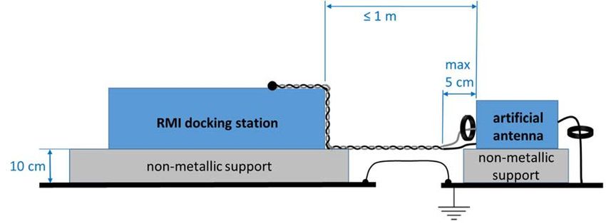
5                   Draft ETSI EN 303 447 V1.2.0 (2020-07)

Intellectual Property Rights
Essential patents

IPRs essential or potentially essential to normative deliverables may have been declared to ETSI. The information
pertaining to these essential IPRs, if any, is publicly available for ETSI members and non-members, and can be found
in ETSI SR 000 314: "Intellectual Property Rights (IPRs); Essential, or potentially Essential, IPRs notified to ETSI in
respect of ETSI standards", which is available from the ETSI Secretariat. Latest updates are available on the ETSI Web
server (https://ipr.etsi.org/).

Pursuant to the ETSI IPR Policy, no investigation, including IPR searches, has been carried out by ETSI. No guarantee
can be given as to the existence of other IPRs not referenced in ETSI SR 000 314 (or the updates on the ETSI Web
server) which are, or may be, or may become, essential to the present document.

Trademarks

The present document may include trademarks and/or tradenames which are asserted and/or registered by their owners.
ETSI claims no ownership of these except for any which are indicated as being the property of ETSI, and conveys no
right to use or reproduce any trademark and/or tradename. Mention of those trademarks in the present document does
not constitute an endorsement by ETSI of products, services or organizations associated with those trademarks.

Foreword
This draft Harmonised European Standard (EN) has been produced by ETSI Technical Committee Electromagnetic
compatibility and Radio spectrum Matters (ERM), and is now submitted for the combined Public Enquiry and Vote
phase of the ETSI standards EN Approval Procedure.

The present document has been prepared under the Commission's standardisation request C(2015) 5376 final [i.6] to
provide one voluntary means of conforming to the essential requirements of Directive 2014/53/EU on the harmonisation
of the laws of the Member States relating to the making available on the market of radio equipment and repealing
Directive 1999/5/EC [i.3].

Once the present document is cited in the Official Journal of the European Union under that Directive, compliance with
the normative clauses of the present document given in table A.1 confers, within the limits of the scope of the present
document, a presumption of conformity with the corresponding essential requirements of that Directive, and associated
EFTA regulations.

                                    Proposed national transposition dates
 Date of latest announcement of this EN (doa):                                    3 months after ETSI publication
 Date of latest publication of new National Standard
 or endorsement of this EN (dop/e):                                               6 months after doa
 Date of withdrawal of any conflicting National Standard (dow):                   18 months after doa

Modal verbs terminology
In the present document "shall", "shall not", "should", "should not", "may", "need not", "will", "will not", "can" and
"cannot" are to be interpreted as described in clause 3.2 of the ETSI Drafting Rules (Verbal forms for the expression of
provisions).

"must" and "must not" are NOT allowed in ETSI deliverables except when used in direct citation.

                                                         ETSI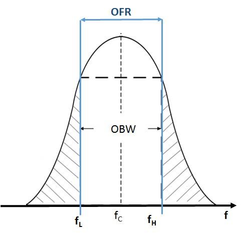
6                   Draft ETSI EN 303 447 V1.2.0 (2020-07)

Introduction
The present document covers Robotic Mowers with Inductive loop systems (RMI) using the frequency range below
148,5 kHz. An RMI system includes:

   •     RMI docking station: charging stations for the robotic mower and the signal generator/antenna connecting
         point for the signals on the integral antenna and boundary wire.

   •     Robotic Mower: receiving part inside the RMI.

   •     Boundary Wire: user installed antenna.

The present document is structured as follows:

   •     Clauses 1 through 3 provide a general description on the types of equipment covered by the present document
         and the definitions, symbols and abbreviations used.

   •     Clause 4 provides the technical requirements specifications, limits and conformance relative to transmitter and
         receiver.

   •     Clause 5 specifies the conditions and information for testing of the equipment and interpretation of the
         measurement results.

   •     Clause 6 specifies the required measurement methods.

   •     Annex A (informative) provides the relationship between the present document and the essential requirements
         of Directive 2014/53/EU [i.3].

   •     Annex B (normative) provides necessary information on used test sites and procedures.

   •     Annex C (informative) provides the justification for missing RX-requirements from ETSI EG 203 336 [i.5].

   •     Annex D (informative) provides information on TX spurious emission limit assessment below 9 kHz.

   •     Annex E (informative) provides information on Change history.

                                                          ETSI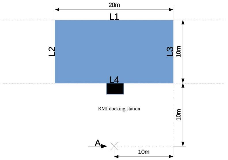
7                    Draft ETSI EN 303 447 V1.2.0 (2020-07)

1             Scope
The present document specifies technical characteristics and methods of measurements for Robotic Mowers with
Inductive loop systems (RMI) below 148,5 kHz.

These radio equipment types are capable of operating in all or part of the frequency bands given in table 1.

                                       Table 1: Permitted range of operation
                                              Permitted range of operation
                                   Transmit                         100 Hz to 148,5 kHz
                                   Receive                          100 Hz to 148,5 kHz
                      NOTE:      It should be noted that the frequency range between 9 kHz and
                                 148,5 kHz is EU wide harmonised for inductive Short Range
                                 Devices according to EC Decision 2017/1483/EU [i.2].

    NOTE 1: The relationship between the present document and essential requirements of article 3.2 of Directive
            2014/53/EU [i.3] is given in Annex A.

The present document only covers RMI systems with antenna sizes smaller than 1,67 km, see
CEPT/ERC/REC 70-03 [i.1], Annex 9.

    NOTE 2: The antenna size is described by the distance between those two points on the antenna that have the
            largest distance between them (e.g. for a rectangle shaped antenna the largest diagonal; for a circular
            shaped antenna the diameter).

2             References

2.1           Normative references
References are either specific (identified by date of publication and/or edition number or version number) or non-
specific. For specific references, only the cited version applies. For non-specific references, the latest version of the
referenced document (including any amendments) applies.

Referenced documents which are not found to be publicly available in the expected location might be found at
https://docbox.etsi.org/Reference/.

    NOTE:     While any hyperlinks included in this clause were valid at the time of publication, ETSI cannot guarantee
              their long term validity.

The following referenced documents are necessary for the application of the present document.

    [1]               ETSI EN 300 330 (V2.1.1) (02-2017): "Short Range Devices (SRD); Radio equipment in the
                      frequency range 9 kHz to 25 MHz and inductive loop systems in the frequency range 9 kHz to
                      30 MHz; Harmonised Standard covering the essential requirements of article 3.2 of
                      Directive 2014/53/EU".

2.2           Informative references
References are either specific (identified by date of publication and/or edition number or version number) or
non-specific. For specific references, only the cited version applies. For non-specific references, the latest version of the
referenced document (including any amendments) applies.

    NOTE:     While any hyperlinks included in this clause were valid at the time of publication, ETSI cannot guarantee
              their long term validity.

The following referenced documents are not necessary for the application of the present document but they assist the
user with regard to a particular subject area.

                                                            ETSI
8 Draft ETSI EN 303 447 V1.2.0 (2020-07)
[i.1] CEPT/ERC/REC 70-03: "Relating to the use of Short Range Devices (SRD)".
[i.2] EC Decision 2017/1483/EU: "Commission Implementing Decision (EU) 2017/1483 of
8 August 2017 amending Decision 2006/771/EC on harmonisation of the radio spectrum for use
by short-range devices and repealing Decision 2006/804/EC".
[i.3] Directive 2014/53/EU of the European Parliament and of the Council of 16 April 2014 on the
harmonisation of the laws of the Member States relating to the making available on the market of
radio equipment and repealing Directive 1999/5/EC.
[i.4] CEPT/ERC/REC 74-01: "Unwanted emissions in the spurious domain".
[i.5] ETSI EG 203 336 (V1.2.1): "Guide for the selection of technical parameters for the production of
Harmonised Standards covering article 3.1(b) and article 3.2 of Directive 2014/53/EU".
[i.6] Commission Implementing Decision C(2015) 5376 final of 4.8.2015 on a standardisation request
to the European Committee for Electrotechnical Standardisation and to the European
Telecommunications Standards Institute as regards radio equipment in support of Directive
2014/53/EU of the European Parliament and of the Council.
[i.7] EGMF Robotic Mowers Boundary Wire Standard RLM003-1.1/2016.
[i.8] EN 50636-2-107:2015: "Safety of household and similar appliances - Part 2-107: Particular
requirements for robotic battery powered electrical lawnmowers", produced by CENELEC.
[i.9] ETSI EN 303 348: "Induction loop systems intended to assist the hearing impaired in the
frequency range 10 Hz to 9 kHz; Harmonised Standard covering the essential requirements of
article 3.2 of Directive 2014/53/EU".
[i.10] ETSI EN 303 454 (V1.1.1): "Short Range Devices (SRD); Metal and object detection sensors in
the frequency range 1 kHz to 148,5 kHz; Harmonised Standard covering the essential requirements
of article 3.2 of Directive 2014/53/EU".
[i.11] Directive 2006/42/EC or the European Parliament and of the Council of 17 May 2006 on
machinery, and amending Directive 95/16/EC (recast).
[i.12] Void.
[i.13] EN 55016-1-1:2010 + A1:2010 + A2:2014: "Specification for radio disturbance and immunity
measuring apparatus and methods -Part 1-1: Radio disturbance and immunity measuring apparatus
- Measuring apparatus", produced by CENELEC.
[i.14] ETSI TS 103 567 (V1.1.1): "Requirements on signal interferer handling".
[i.15] ETSI TS 103 051 (V1.1.1) (08-2011): "Electromagnetic compatibility and Radio spectrum
Matters (ERM); Expanded measurement uncertainty for the measurement of radiated
electromagnetic fields".
3 Definition of terms, symbols and abbreviations
3.1 Terms
For the purposes of the present document, the terms given in ETSI EN 300 330 [1] and the following apply:
99 % OBW function: measurement function of a spectrum analyser to measure the OBW
antenna: integral antenna, boundary loop, and/or guidance loop (both dependent and independent) which are used in
the RMI
NOTE 1: The inductive wire loops are installed dependent from the shape of the garden.
NOTE 2: To clarify the different loops see figure 2.
ETSI9 Draft ETSI EN 303 447 V1.2.0 (2020-07)
boundary loop: inductive wire loop which is defined by manufacturer and prepared by the user
NOTE 1: It can be implemented as a single or multiple turn coil installed by the user in accordance with instruction
from the manufacturer for the purpose of generating magnetic fields to determine the working area.
NOTE 2: To clarify the different loops see figure 2.
dependent guidance loop: guidance loop which is connected to boundary loop (e.g. via a T-junction) and the RMI
docking station
NOTE: To clarify the different loops see figure 2.
guidance loop: inductive wire loop which is defined by manufacturer and prepared by the user
NOTE: To clarify the different loops see figure 2.
inductive loop: electrical loop either wire or coil, where current is fed in order to generate a magnetic field intended for
guidance and/or communication with the robotic mower
NOTE: To clarify the different loops see figure 2.
integral antenna: single or multiple turn inductive loop preinstalled inside the RMI docking station
NOTE: To clarify the different loops see figure 2.
integral receiving antenna: single or multiple turn inductive loop preinstalled inside the robotic mower
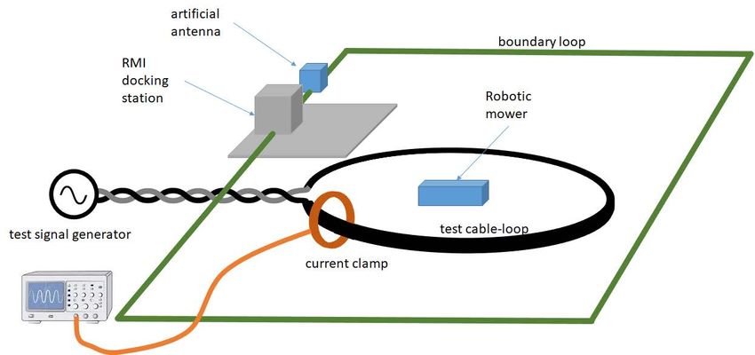
Occupied BandWidth (OBW): width of a frequency band such that, below the lower and above the upper frequency
limits, the mean powers emitted are each equal to 0,5 % of the total mean power of a given emission
NOTE: To clarify Occupied BandWidth (OBW), see figure 1.
Figure 1: Occupied BandWidth (OBW)
RMI docking station: charging station for the robotic mower and the signal generator for the inductive loop(s) and, if
applicable, integral antenna(s)
NOTE: The RMI docking station can be seen as the signal generator/antenna connecting point. In addition, it is
the automatic battery charging facility located on or within the working area.
robotic mower: mobile part of the RMI including cutting means
NOTE: It is the receiving part inside the RMI.
Robotic Mower with Inductive loop system (RMI): system that include robotic mower, power supply, docking
station, and inductive loop(s)
working area: area in which the RMI can function
ETSI10 Draft ETSI EN 303 447 V1.2.0 (2020-07)
Figure 2: Overview of an RMI system, including the different possible antenna/loops
3.2 Symbols
For the purposes of the present document, the symbols given in ETSI EN 300 330 [1] and the following apply:
CA filtering capacitors of the artificial antenna
fC centre frequency of the OFR
fH highest frequency of the OFR
fL lowest frequency of the OFR
fSH higher frequency border between OOB and spurious domain
fSL lower frequency border between OOB and spurious domain
ICM Common mode current
IDM Differential mode current
LA inductive part of the artificial antenna
RA low frequency resistive part of the artificial antenna
RC common mode resistive part of the artificial antenna
RD high frequency resistive part of the artificial antenna
tSWT sweept time for TX measurement
3.3 Abbreviations
For the purposes of the present document, the abbreviations given in ETSI EN 300 330 [1] and the following apply:
CM Common Mode
DM Differential Mode
EGMF European Garden Machinery industry Federation
IHR Interferer Handling Requirements
OBW Occupied BandWidth
OFR Operating Frequency Range
OOB Out Of Band
RMI Robotic Mower with Inductive loop system
RX Receiver
TX Transmitter
ETSI11 Draft ETSI EN 303 447 V1.2.0 (2020-07)
4 Technical requirements specifications
4.1 Environmental profile
The technical requirements of the present document apply under the environmental profile for operation of the
equipment, which shall be in accordance with its intended use. The equipment shall comply with all the technical
requirements of the present document at all times when operating within the boundary limits of the operational
environmental profile defined by its intended use.
4.2 General
4.2.1 Wanted technical performance criteria
In general, the robotic mower shall stay in its current operational mode (see clause 4.2.2.2), this is the wanted technical
performance criteria of the RMI system.
For the purpose of the receiver performance tests, the RMI shall be able to handle two interference scenarios:
• Scenario 1: under the presence of an interfering signal, the robotic mower shall be able to detect a loss of the
boundary loop signal (see clause 6.3.3.2).
• If the mower detects the loss of boundary signal, it shall react in the same way as required within the "safe
mode" (see clause 4.2.2.3). The loss of the boundary loop signal can be based on, but not limited to, switching
off the boundary loop signal, disconnection of the boundary loop, or blocking of the receiver within the
mower.
• Scenario 2: under the presence of an interfering signal, the robotic mower shall be able to detect the passage of
the boundary wire (see clause 6.3.3.3).
4.2.2 RMI modes
4.2.2.1 General
In this clause all general considerations for the testing of the inductive parts for the RMI in the frequency range from
100 Hz to 148,5 kHz are given.
Modes being part of an RMI are explained in the following clauses.
The manufacturer shall provide information (e.g. installation requirements), number and kind of antennas used by the
RMI (e.g. boundary loop(s), guidance loop(s), integral antenna(s), etc.), see figure 2. A RMI is fabricated by one
manufacturer. There is no option to swap e.g. a mower to another boundary installation. Based on the general nature
(TX and RX) of an RMI, covered by the present document, the RMI shall be tested as a system.
The test set-up of the different modes shall be performed as described in clause 6.1 and Annex B.
4.2.2.2 Operational Modes
Operational modes of an RMI are when the robotic mower is travelling around, mowing grass, returning to the docking
station and charging the battery in the docking station.
During the operational modes different combinations of the RMI antennas are active.
The test shall be performed for each active antenna in each operational mode, unless the transmitting signal to the same
antenna is identical over different modes, the test of the active antenna shall be performed only once.
ETSI12 Draft ETSI EN 303 447 V1.2.0 (2020-07)
4.2.2.3 Safe Mode
If the robotic mower does not receive its boundary signal adequately, the robotic mower switches into safe mode. This
loss of signal may either be caused by a stop of the signal generation or by interference.
The safe mode is indicated that after a loss of signal the robotic mower does not travel more than 1 m and the cutting
means stops within 5 seconds, see EN 50636-2-107 [i.8], clause 22.104.2.
4.2.3 Presentation of equipment for testing purposes
Each RMI submitted for testing shall fulfil the requirements of the present document.
Additionally, technical documentation and operating manuals, sufficient to make the test, shall be supplied.
To simplify and harmonise the testing procedures between different testing laboratories, measurements shall be
performed, according to the present document, on samples defined in clause 4.2.2 of ETSI EN 300 330 [1].
4.3 Transmitter conformance requirements
4.3.1 Operating Frequency Range (OFR)
4.3.1.1 Applicability
This requirement applies to all RMI.
4.3.1.2 Description
The operating frequency range is the frequency range over which the RMI is transmitting. The operating frequency
range of the RMI is determined by the lowest (fL) and highest frequency (fH):
OFR = fH-fL
An RMI can have more than one operating frequency range (relating to the operational modes and antennas of the RMI
system, see clause 4.2.2).
For a single frequency system the OFR is equal to the Occupied BandWidth (OBW) of the RMI system as described in
figure 3.
Figure 3: Operating Frequency Range (OFR)
ETSI13 Draft ETSI EN 303 447 V1.2.0 (2020-07)
4.3.1.3 Limits
The operating frequency range for intentional emissions shall be within the following limits:
• Upper edge of the operating frequency range: fH ≤ 148,5 kHz.
• Lower edge of the operating frequency range: fL ≥ 100 Hz.
For the spurious and OOB emission measurement procedures in clauses 4.3.3 and 4.3.4 the OFR shall be calculated as:
fH - fL and the centre frequency as:
݂ = ಹଶାಽ
4.3.1.4 Conformance
The conformance test suite for operational frequency range shall be as defined in clause 6.1 (table 7).
4.3.2 Transmitter H-field requirements
4.3.2.1 Applicability
This requirement applies to all RMI.
4.3.2.2 Description
The radiated H-field is defined in the direction of maximum field strength of the RMI.
4.3.2.3 Limits
The H-field limits for the bands 100 Hz to 148,5 kHz are provided in table 2.
Table 2: H-field limits between 0,1 kHz and 148,5 kHz
Frequency range (kHz) H-field strength limit (Hf) dBμA/m at 10 m
0,1 ≤ f < 9 82
9 ≤ f < 60 72 descending 10 dB/dec above 0,03 MHz
60 ≤ f < 90 42
90 ≤ f < 119 42
119 ≤ f < 135 42
135 ≤ f < 140 42
140 ≤ f < 148,5 37,7
NOTE: For the range 0,1 kHz to 9 kHz the limit is in line with CEPT/ERC/REC 70-03 [i.1],
Annex 9.
For the range 9 kHz to 148,5 kHz it is in line with EC Decision 2017/1483/EU [i.2].
4.3.2.4 Conformance
The conformance test suite for transmitter H-field requirements shall be as defined in clause 6.1 (table 7).
4.3.3 Transmitter spurious emissions
4.3.3.1 Applicability
This requirement applies to all RMI.
ETSI14 Draft ETSI EN 303 447 V1.2.0 (2020-07)
4.3.3.2 Description
The transmitter spurious emissions for a single frequency system are to be considered in frequency ranges defined in
figure 3 (f < fSL and f > fSH).
Figure 4: Out of band and spurious domain of a single frequency system
The following additional conditions applying for fSH:
1) For systems with fH ≤ 9 kHz: fSH shall be set to 27 kHz.
2) For systems with fH > 9 kHz: fSH is the smallest of:
- f = fC + 2,5 × OFR; or
- f = 148,5 kHz.
NOTE 1: fSH under number 1) above was calculated based on an assumed fC of 4,5 kHz and OBW of 9 kHz.
NOTE 2: Bullet two of number 2) above ensures that the spurious limits of CEPT/ERC/REC 74-01 [i.4] applies
above 148,5 kHz.
The following additional conditions applying for fSL:
1) For systems with calculated fSL < 100 Hz: fSL is set to 100 Hz.
2) The fSL and fSH shall be calculated based on the OFR result, see clause 4.3.1 (definition OFR) and figure 4 for
the calculation.
4.3.3.3 Limits
The spurious emissions shall not exceed the limits given in table 3.
ETSI15 Draft ETSI EN 303 447 V1.2.0 (2020-07)
Table 3: TX spurious emissions
State 100 Hz ≤ f < 10 MHz 10 MHz ≤ f < 30 MHz 30 MHz ≤ f < 1 GHz
Operating 46,5 dBμA/m at 100 Hz descending 3 dB/oct -3,5 dBμA/m -36 dBm
100 Hz ≤ f < 4,78 MHz 4,78 MHz ≤ f < 30 MHz 30 MHz ≤ f < 1 GHz
Standby 25 dBμA/m at 100 Hz descending 3 dB/oct -22 dBμA/m -57 dBm
NOTE 1: For the frequency range below 9 kHz: the limits are on voluntary basis, based on an EC request. ETSI
proposed the limits to ECC to be implemented in CEPT/ERC/REC 74-01 [i.4], for more details see Annex D
of the present document.
NOTE 2: For the frequency range above 9 kHz: the limits are in line with CEPT/ERC/REC 74-01 [i.4], Annex 2.
4.3.3.4 Conformance
The conformance test suite for transmitter spurious emissions shall be as defined in clause 6.1 (table 7).
4.3.4 Transmitter Out Of Band (OOB) emissions
4.3.4.1 Applicability
This requirement applies to all RMI.
4.3.4.2 Description
The transmitter out of band emissions are to be considered in frequency ranges defined in figure 4 (between fSL and fL
and between fH and fSH).
The fSL and fSH shall be calculated based on the OFR result, see clause 4.3.1 (definition OFR) and clause 4.3.3.2,
figure 4 for the calculation.
4.3.4.3 Limits
The OOB limits are visualized in figure 4 (clause 4.3.3.2); they are descending from the limits from table 2 at fH/fL with
10 dB/decade.
4.3.4.4 Conformance
The conformance test suite for Transmitter out of band emissions is provided in clause 6.1 (table 7).
4.4 Receiver conformance requirements
4.4.1 Introduction
The justification for the RX-requirements of RMI is provided in Annex C. The receiver concept on signal interferer
handling in ETSI TS 103 567 [i.14] is used. The specific RMI justification for the receiver requirements is provided:
• For receiver unwanted emissions, see clause C.1.
• For Receiver Baseline Sensitivity and Receiver Baseline Resilience, see clause C.2.
4.4.2 Receiver Baseline Sensitivity
4.4.2.1 Applicability
This requirement applies to all RMI.
ETSI16 Draft ETSI EN 303 447 V1.2.0 (2020-07)
4.4.2.2 Description
The robotic mower is running "trough" the test garden (see clause B.1.5) without switching into a safe mode. The
largest distance to the boundary wire will happen if the mower is in the middle to the test set-up, see clause 6.3.2,
figures 5 and 6 and related parameter for an artificial antenna in clause B.1.1.
4.4.2.3 Limits
The robotic mower has to run longer than 60 seconds without switching into the safe mode, see clause 4.2.2.3.
4.4.2.4 Conformance
The conformance test suite for Receiver Baseline Sensitivity shall be as defined in clause 6.1 (table 7).
4.4.3 Receiver Baseline Resilience
4.4.3.1 Applicability
This requirement applies to all RMI.
4.4.3.2 Description
Receiver Baseline Resilience is a measure of the capability of the receiver to receive a wanted modulated signal without
exceeding a given degradation due to the presence of an unwanted input signal at any frequencies other than those of
the receiver spurious responses.
The test shall be in the operational mode (real scenario, see clause 4.2.2.2).
The RMI shall achieve the wanted technical performance criteria, see clause 4.2.1, in the presence of the interfering
signal.
4.4.3.3 Limits
The Receiver Baseline Resilience limits in table 4 shall be fulfilled.
Table 4: Receiver Baseline Resilience requirements
In-band signal OOB signal Remote-band signal
Frequency f = fc f = fc ± OFR f = fc ± 10 × OFR
Interferer signal 98 dBµA/m - 20log10 (f/10 kHz) 98 dBµA/m - 20log10 (f/10 kHz) 98 dBµA/m - 20log10 (f/10 kHz)
level
Kind of CW CW CW
interferer signal
NOTE: The industry standard for RMI (Source: EGMF [i.7]) proposes that robotic mower installations should never
be closer than 1 meter and the RMS current in the wire should never exceed 500 mA. When an interfering
standard garden is located at a distance of 1 m with long side to long side the H field from a 500 mA current
will be 98 dBuA/m (or 100 nT for B-field). Robotic mowers use coils as antennas and the Electromagnetic
Force (EMF) generated in those antennas are proportional to the derivative of the signals. Therefore, when
doubling the frequency of the interfering signal the voltage generated in the antenna will also double. The
100 nT is therefore normalized to a state of the art value for robotic mower signal centre frequency of 10 kHz.
4.4.3.4 Conformance
The conformance test suite for Receiver Baseline Resilience shall be as defined in clause 6.1 (table 7).
ETSI17 Draft ETSI EN 303 447 V1.2.0 (2020-07)
5 Testing for compliance with technical requirements
5.1 Environmental conditions for testing
Tests defined in the present document shall be carried out at representative points within the boundary limits of the
operational environmental profile defined by its intended use.
Where technical performance varies subject to environmental conditions, tests shall be carried out under a sufficient
variety of environmental conditions (within the boundary limits of the operational environmental profile defined by its
intended use) to give confidence of compliance for the affected technical requirements.
5.2 General conditions for testing
Clause 5.3 of ETSI EN 300 330 [1] provides information on test conditions, power supply and ambient temperature.
ETSI TS 103 051 [i.15] provides additional information on measurement uncertainty.
5.3 Artificial antenna
The artificial antenna is described in clause B.1.1.
5.4 Measuring receiver
The term "measuring receiver" refers to a selective voltmeter, oscilloscope, a spectrum analyser or a measurement
instrument according to [i.13]. The resolution bandwidth and detector type of the measuring receiver are given in
tables 5 and 6.
Table 5: Resolution Bandwidth and detector type for magnetic field measurements
Frequency: (f) Detector type Resolution bandwidth
100 Hz ≤ f < 500 Hz Peak 10 Hz
500 Hz ≤ f < 9 kHz Peak 200 Hz
9 kHz ≤ f < 150 kHz Quasi Peak 200 Hz
150 kHz ≤ f < 30 MHz Quasi Peak 9 kHz
30 MHz ≤ f ≤ 1 000 MHz Quasi Peak 120 kHz
Table 6: Resolution Bandwidth and detector type for spurious and OOB measurements [i.4]
Frequency: (f) Detector type Resolution bandwidth
100 Hz ≤ f < 500 Hz RMS 10 Hz
500 Hz ≤ f < 9 kHz RMS 100 Hz
9 kHz ≤ f < 150 kHz RMS 1 kHz
150 kHz ≤ f < 30 MHz RMS 10 kHz
30 MHz ≤ f ≤ 1 000 MHz RMS 100 kHz
In tables 5 and 6 a resolution bandwidth of 10 Hz is requested for the measurements up to 500 Hz. If such resolution
bandwidth is not available in the measurement receiver a resolution bandwidth up to 100 Hz shall be used. The
measurement bandwidths and any related calculations shall be stated in the test report.
If a different detector type and resolution bandwidth will be used for the conformance test this is specified in the related
subclauses of clause 6.
ETSI18 Draft ETSI EN 303 447 V1.2.0 (2020-07)
6 Conformance methods of measurement for transmitters
and receivers
6.1 General
Table 7 gives an overview of the relevant conformance tests and test conditions for the essential requirements in
clause 4.
Table 7: Overview of Conformance tests
Test setup and procedure
Conformance
Essential requirements Boundary loop and (dependent)
tests Integral antenna
guidance loop
OFR, clause 4.3.1 6.2.1 Clauses B.1.2 and B.1.3 B.2
H-field, clause 4.3.2 6.2.2 Clauses B.1.2 and B.1.3 B.2
Transmitter unwanted 6.2.3 for f < 30 MHz: see clauses B.2
emission (spurious and out B.1.2, B.1.3 and B.1.4
of band emissions),
clauses 4.3.3 and 4.3.4 for 30 MHz < f < 1 GHz: not applicable
(see note)
Receiver Sensitivity 6.3.2
Receiver Blocking, 6.3.3 Not applicable Not applicable
clause 4.4.3
NOTE: Artificial antenna is only specified for the frequency range below 30 MHz. In a real scenario a large
boundary loop is low pass filter and therefore radiates no TX unwanted emissions above 30 MHz.
In addition the harmonics of the fundamental will not be present above 30 MHz (e.g. at 30 MHz it
would be the 202nd harmonic of the highest fundamental frequency).
6.2 Transmitter conformance methods
6.2.1 OFR
Dependent on the used RMI antennas the measurement shall be made with one of the test setups from Annex B. For
boundary and guidance loops the test setup and procedure from clause B.1 (artificial antenna) and for integral antennas
the test setup and procedure from clause B.2 (anechoic chamber) shall be used.
Based on the very low frequencies the test has to be performed within two steps.
Step 1:
The transmission shall be measured using a measuring receiver according to clause 5.4 with the following settings:
Start frequency: 100 Hz
Stop frequency: 148,5 kHz
Resolution Bandwidth: 200 Hz
Video Bandwidth: ≥ 300 Hz
Detector mode: RMS
Display mode: max hold over 10 sweeps (one measurement)
Sweep time: increase the sweep time and reset max hold after each measurement until the difference
between two consecutive measurements of the amplitude of the spectrum is less than 0,5 dB
ETSI19 Draft ETSI EN 303 447 V1.2.0 (2020-07)
The following values shall be recorded:
• fH_step1 as the right most frequency above the center frequency fc shall be recorded where the level is 23 dB
lower as the maximum.
• fL_step1 as the left most frequency below the center frequency shall be recorded where the level is 23 dB lower
as the maximum.
• fH_step1 and fL_step1 shall be recorded.
• tSWT: final sweep time of step 1.
Step 2:
• Start frequency: 100 Hz or 0,8 × fL_step1 whatever is higher
• Stop frequency: 148,5 kHz or 1,5 × fH_step1 whatever is lower
• Resolution Bandwidth: 30 Hz if start frequency is below 500 Hz
200 Hz if start frequency is above 500 Hz
• Video Bandwidth: larger than the resolution bandwidth
• Detector mode: RMS
• Display mode: max hold over 10 sweeps
• Sweep time: tSWT
The following values shall be recorded:
• fH as the frequency of the upper marker resulting from the "OBW"-function of a spectrum analyser, using
99 % of the power (see figure 3). Alternatively the right most frequency above the center frequency fc shall be
recorded where the level is 23 dB lower as the maximum.
• fL as the frequency of the lower marker resulting from the "OBW"-function of a spectrum analyser, using
99 % of the power (see figure 3). Alternatively, the left most frequency below the center frequency shall be
recorded where the level is 23 dB lower as the maximum.
• fC is the center frequency.
• OFR= fH - fL.
The results out of step 2 are to be compared with the limits in clause 4.3.1.3.
NOTE 1: Some RMI are sending a DC current or voltage in the loop wire to feed slave devices. This DC signal will
always have a small bandwidth, but will never create high radiated emission via the loop and the
interference on radio devices at these frequencies will be low (no radio application known in the range
< 100 Hz).
NOTE 2: Addition homologation measurements have shown that a state of the art power supply installation (50 Hz)
and AC/DC converters create high emissions. Based on the technical implementation, it is not always
possible to differentiate the radiated emission of an RMI system from the unwanted emission from the
power supply installation/devices. This also applies to measurements performed inside an anechoic
chamber.
6.2.2 H-field
Dependent on the used RMI antennas the measurement shall be made with one of the test setups from Annex B
according to table 7.
The transmission shall be measured using a measuring receiver according to clause 5.4 with the following settings:
• Start frequency: 0,8 × fL (see clause 6.2.1)
ETSI20 Draft ETSI EN 303 447 V1.2.0 (2020-07)
• Stop frequency: 1,2 × fH (see clause 6.2.1)
• Resolution Bandwidth: according to clause 5.4, table 5
• Video Bandwidth: ≥ Resolution Bandwidth
• Detector mode: according to clause 5.4, table 5
• Display mode: max hold over 10 sweeps
• Sweep time: tSWT (see clause 6.2.1)
• The maximum H-Field results are to be compared with the limits in clause 4.3.2.3.
6.2.3 Transmitter unwanted emissions (spurious and OOB emissions)
Dependent on the used RMI antennas the measurement shall be made with one of the test setups from Annex B
according to table 7.
The transmission shall be measured using a measuring receiver according to clause 5.4 with the following settings:
• Start frequency: according to clause 5.4, table 6
• Stop frequency: according to clause 5.4, table 6
NOTE: For each frequency range out of table 6 one measurement is to be performed.
• Resolution Bandwidth: according to clause 5.4, table 6
• Video Bandwidth: ≥ Resolution Bandwidth
• Detector mode: according to clause 5.4, table 6
• Display mode: maxhold over > 10 sweeps
• Sweep time: increase the sweep time and reset max hold after each measurement until the
difference between two consecutive measurements of the amplitude of the
spectrum is less than 0,5 dB
The maximum unwanted emission (spurious and OOB) results are to be compared with the limits in clause 4.3.3.3.
6.3 Receiver conformance methods
6.3.1 Receiver spurious emissions
Not applicable, see clause C.1.
6.3.2 Receiver Baseline Sensitivity
6.3.2.1 General
The test setup is visualized in figures 5 and 6.
The RMI docking station shall be operated with a boundary loop according to figures 5 and 6 with an artificial antenna
(or artificial load with 2 Ohm and 200 µH, see clause B.1.1) as load in series.
The test shall be carried out according a test site in clause C.1 of ETSI EN 300 330 [1].
The boundary wire shall lie on a non-metallic ground and the minimum distance to a metallic ground plane shall be
0,75 m.
ETSI21 Draft ETSI EN 303 447 V1.2.0 (2020-07)
The geometrical centre of the receiver(s) in the robotic mower shall be placed to the centre of the test-loop (e.g. X=0
(see figure 6)) and shall stay there during the test (e.g. the robotic mower wheels may be deactivated or lifted from the
ground). Any possible switch off mechanism (e.g. if the robotic mower detects no movement) shall not affect the test.
Figure 5: Schematic test set-up for RX-Sensitivity test
Figure 6: Schematic test set-up for RX-Sensitivity test (view from top)
ETSI22 Draft ETSI EN 303 447 V1.2.0 (2020-07)
6.3.2.2 Receiver-Baseline Sensitivity Test
Step 1: Place the robotic mower in the middle of the test set-up.
Step 2: Activate the RMI system.
Step 3: Start the robotic mower with the operation mode. The robotic mower shall be adjusted in such a way that
the robotic mower will keep the position in the middle of the test set-up (e.g. by deactivation of the wheel,
lifting up).
Step 4: If the RMI meets the wanted technical performance criteria (see clause 4.2.1) at all times, this means
working longer than 60 seconds as intended, then the test shall be considered as passed.
Otherwise, the test is considered as failed.
6.3.3 Receiver Baseline Resilience
6.3.3.1 General
The fulfilment of the RMI performance criteria in the operational mode (see clause 4.2.1) shall be tested in presence of
an inference signal according to clause 4.4.3.3, table 4 (frequencies, magnetic field).
The test setup is visualized in figures 7 and 8.
The RMI docking station shall be operated with a boundary wire arrangement according to figures 7 and 8 in
combination with an artificial antenna (or artificial load with 2 Ohm and 200 µH, see clause B.1.1) as load in series.
The test shall be carried out according a test site in clause C.1 of ETSI EN 300 330 [1].
A test loop with a radius R shall be used to create an interfering magnetic field. The test loop shall lie on a non-metallic
ground and the minimum distance to metallic ground plane shall be 0,75 m. The test loop and the boundary wire shall
be on the same horizontal level.
The geometrical centre of the receiver(s) in the robotic mower shall be placed to the centre of the test-loop (e.g. X=0
(see figure 8)) and shall stay there during the test (e.g. the robotic mower wheels may be deactivated or lifted from the
ground). Any possible switch off mechanism (e.g. if the robotic mower detects no movement) shall not affect the test.
The radius R of the test-loop shall be in minimum 4 times the maximum dimension r of the robotic mower (see
figure 6).
The maximum interfering H-Field at X = 0 can be calculated from the loop current I (into the test-loop) with the
following formula:
= ܪଶோ
ூ
(1)
The required output current to achieve the magnetic field from clause 4.4.3.3, table 4 at the robotic mower shall be
generated with a test signal generator at the test frequencies from table 4.
For each test frequency the "reaction" of the RMI shall be recorded and checked against the wanted technical
performance criteria from clause 4.2.1.
The RX test includes two separate test scenarios:
• Test 1: see clause 6.3.3.2, if the robotic mower can handle a lost signal.
• Test 2: see clause 6.3.3.3. if the robotic mower can handle a passage of the boundary wire.
6.3.3.2 Test 1: if robotic mower can handle a lost signal
Step 1.1: Initially, the test signal generator shall be switched off.
Step 1.2: The RMI system shall be configured so that the wanted technical performance criteria are met: the wanted
criteria are considered to be met as long as the receiver always works as intended. Calculate the limit of
the interferer current according to clause 4.4.3.3, table 4 and equation (1).
ETSI23 Draft ETSI EN 303 447 V1.2.0 (2020-07)
Step 1.3: The test signal generator is then switched on at fC.
Step 1.4: The test signal generator shall then be adjusted in carrier current from zero up to the limit given in
clause 4.4.3.3, table 4.
Step 1.5: If the robotic mower goes into safe mode or into a state which is not declared then this magnetic field
shall be noted.
Step 1.6: With the interferer limit according to clause 4.4.3.3, table 4, turn off the RMI transmitter, so there is only
the signal from the interferer. The robotic mower has to detect the loss of its signal and go into safe mode
(see clause 4.2.1).
Step 1.7: The measurements steps 1.1 to 1.6 shall be repeated at the frequency for OOB and remote-signal as
requested in clause 4.4.3.3, table 4.
If the RMI meets the wanted technical performance criteria (see clause 4.2.1) at all times, then the test shall be
considered as passed.
Otherwise, the test is considered as failed.
Figure 7: Schematic test set-up for the RX-blocking test 1
ETSIYou can also read