Dynamic Modelling of a Solar Energy System with Vehicle to Home and Vehicle to Grid Option for Newfoundland Conditions
←
→
Page content transcription
If your browser does not render page correctly, please read the page content below
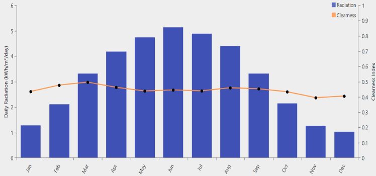
EJECE, European Journal of Electrical Engineering and Computer Science
 ISSN: 2736-5751

 Dynamic Modelling of a Solar Energy System with
 Vehicle to Home and Vehicle to Grid Option for
 Newfoundland Conditions
 Raghul Suraj Sundararajan, M. Tariq Iqbal

 mode, the car disconnects from the house and feeds power to
 Abstract — The dynamic modelling of a solar energy system the grid [5], [6]
with vehicle to home (V2H) and vehicle to grid (V2G) options In this paper, we present a solution that addresses this
for Newfoundland conditions is discussed in this paper. A site problem by combining the Vehicle to Home (V2H) and
(13 Polina Road) was chosen in St. John's, Newfoundland,
Canada. An optimized system was built for the chosen site using
 Vehicle to Grid (V2G) principles, as well as a hybrid PV
BEopt, Homer, and MATLAB software’s to meet the house's system [7]. For system sizing and dynamic modelling, BEopt,
energy demand. Furthermore, smart current sensors installed in HOMER, and MATLAB were used.
the house are used to incorporate the V2H and V2G concepts.
The Nissan Leaf's battery is used to supply household loads in
V2H operation mode when the power supplied by the PV panel II. SITE DETAILS
and the storage energy in the inhouse battery is less than the
load's energy demand. In V2G mode, the vehicle is only linked A. Selected Site and Solar Insolation
to grid. Along with the simulation results, detailed system
 The research location was selected as 13 Polina Road in St.
dynamic modelling is also presented. There are nine different
system control modes that are proposed and simulated. John's, Newfoundland, Canada. It has a total area of 185.89
 m2. In St. John's, Newfoundland, Canada, Fig. 1 depicts a
 Index Terms — PV, V2H, V2G, Renewable energy, Hybrid monthly solar radiation and clearness index profile for the
power systems. chosen region. The clearness index varies from 0.20 to 0.30.
 The average solar insolation is 3.15 kWh/m2/day, with a
 range of 1.28 kW/m2/day to 5.14 kWh/m2/day.
 I. INTRODUCTION
 Electric vehicles (EVs) are the next wave in the global
transportation industry. EV’s have various advantages, more
powerful, emit no pollution and act as mobile power
reservoirs. EV’s need to be charged, renewable sources of
energy, such as solar energy systems, help satisfy the energy
demand and also to reduce the carbon footprint [1] Since
renewables are inherently variable, backup battery is
required. Since EVs act as reservoirs, the concept of Vehicle
to Home (V2H) and Vehicle to Grid (V2G) can be
implemented [2], [3]. The proposed system implements V2H
 Fig. 1. Solar insolation and clearness index of selected site.
and V2G concept. The in-house battery acts as backup
battery, to supply uninterrupted power the home load’s when B. Sites Power Requirement from BEopt
the power produced by PV is not sufficient to meet the load’s The annual power demand for the chosen site was
energy demand. The Nissan Leaf (40kW variant) is being calculated using BE opt tools. The annual power consumption
considered as EV, for use in the V2H concept. Furthermore, of the house is approximately 21111 kWh. This covers all
the implemented system has level 1 and level 2 chargers for loads in the building, such as heaters, boilers, lighting,
charging the Nissan Leaf's battery during charging mode, as ventilation, and other factors including plugin loads.
well as a converter for charging the inhouse battery and
powering the load at the same time. Until the produced power C. Sites Load and Photovoltaic Panel Area Calculation
is less than the load's energy requirement, the designed The daily load requirement for the site is 11.90 kW. The
system uses PV as the primary source of power. However, if hourly electricity demand rises at 6 a.m. and falls by 9 p.m.,
the power produced by PV was less compared to load’s with an all-time high between 6 and 7 PM. Fig. 2 shows the
energy demand, the inhouse battery is used to power the loads seasonal load profile from HOMER, which shows that the
in this situation. When the system reaches 30% SOC, it months of November to April have higher per hour energy
switches to V2H, which means the Nissan Leaf's battery will demand than the months of May to October.
be discharged to satisfy the load's energy demand [4]. In V2G

Submitted on May 23, 2021. M. Tariq Iqbal, Memorial University of Newfoundland, Canada.
Published on June 13, 2021. (e-mail: tariq@mun.ca)
Raghul Suraj Sundararajan, Memorial University of Newfoundland, Canada.
(e-mail: rssundararaj@mun.ca)

 DOI: http://dx.doi.org/10.24018/ejece.2021.5.3.329 Vol 5 | Issue 3 | June 2021 45
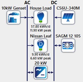
EJECE, European Journal of Electrical Engineering and Computer Science
 ISSN: 2736-5751

 Bus voltage = 48 V
 For desired power output, number of strings = 20 Strings
 Number of panels in each string = 2
 Including derating factor the number of strings = 24 Strings
 B. Battery
 For this application, the Trojan SAGM 12 105 battery was
 selected. The following is the battery calculation, including
 three days of backup. The calculations show that 360 batteries
 are needed without backup. Since the design included a 10kW
 Fig. 2. Annual load chart from HOMER. backup generator, the number of batteries needed was
 reduced to 80.
 III. SYSTEM SIMULATION
 The software Hybrid Optimization of Multiple Energy ℎ ℎ
 = 57804
Resources (HOMER) was used to size the system. A
schematic of the proposed system is shown in Fig. 4. The 3 = 57804 × 3 = 173413 ℎ
solar panel used was a Canadian Solar CS6U-340M, the 173413
 40% = = 433532.5 ℎ
battery was a Trojan SAGM 12 105, the inverter was 20 kW, 0.4
the home load profile was 57.8 kWh/d with a peak of (> 80 ) = 433532.5 × 1 = 433532.5 ℎ
 433532.5
11.90 kW and a backup, a 10 kW genset is installed, which ℎ = = 9031.92 ℎ
has no effect on the system's dynamics. 48
 9031.92
 = ( ) × 4 = 360
 100
 C. Nissan Leaf – 40 kW variant
 Nissan Leaf with a 40 kWh lithium-ion battery pack and a
 6.6 kW onboard charger is considered in this concept. A built-
 in bidirectional converter for charging and discharging is
 another benefit of the Nissan Leaf (reeling power to home).
 Charging and discharging are the two modes of operation for
 the Nissan Leaf. Nissan Leaf is reeling out power or
 discharging its battery, when the PV panels and battery are
 Fig. 4. Schematic of proposed system in HOMER. unlikely to fulfill the energy demand of the home load, this
 A. Photovoltaic Panel mode is used [8], [9]. When the Nissan Leaf is in charging
 mode, the following is assumed. The electric vehicle is
 The Canadian Solar CS6U 340M module, with a 340 W
output and a 1.8 m2 surface area, was used in this design. charged with the excess energy generated or stored after the
 home loads are met [10].
 In St. John's, the average daily sunlight is 1633 hours for
272 days. D. Inverter
 The peak load value is about 19.90 kW and deferrable
Output from BEopt = 21111 kWh/year loads peak value is 6.60kW, an inverter with a 20 kW output
Per day = 57.8 kWh/day capacity is considered for the design. In this case, the inverter

 = has two outputs: 120 V and 240 V.
 ℎ
 = 12.930
For PV sizing considering derating factor as 0.8 IV. DYNAMIC MODELLING

 =
 Simulink was used to simulate the proposed architecture.
 = 16.1633 kW PV array, MPPT controller, in-house battery, boost
 converters, inverter, level 1 and level 2 chargers, Nissan Leaf
 =
 340 battery and V2G inverter are all included in the simulation.
For calculated power output The overall block diagram of the proposed system is shown
 = 38 Modules in Fig. 5. PV power is used to charge the in-house battery via
For derating factor a charger, and an inverter with two outputs at 120 V and
 = 48 Modules 240 V is used to convert the stored power in the battery to AC
Area calculation to power the house load. Furthermore, a Nissan leaf charger
Area of one Canadian solar CS6U 340 M module is 1.88m2
 with level 1 and level 2 charging capabilities [8] is designed,
For desired power output
 as well as a converter to step down 360 V to 48 V, which is
 = 38 x 1.88
 used to charge the in-house battery and simultaneously
 = 71.44m2
 powering the house loads [9] and a 10 kW genset is
For derating factor
 = 48 x 1.88 incorporated which is used only as a backup and has no
 = 90.24m2 impact on dynamics of the system. Overview of simulated
Available area = 185.89 m2 system is illustrated in Fig. 6. The system is simulated for

 DOI: http://dx.doi.org/10.24018/ejece.2021.5.3.329 Vol 5 | Issue 3 | June 2021 46
EJECE, European Journal of Electrical Engineering and Computer Science
 ISSN: 2736-5751

charging and discharging the in-house battery, powering
loads with the in-house battery, a dual outlet inverter that
outputs 120 V and 240 V, a Nissan leaf charger with level 1
and level 2 charging.
 Discharge Nissan Leaf to charge inhouse battery, discharge
inhouse battery at night to charge Nissan Leaf, discharge
Nissan Leaf to implement V2G mode and a dump load to
remove excess power. Automatic state of charge overrides is
included in the system, with 30 percent SOC charge ON
(inhouse battery) and 40 percent SOC charge ON (Nissan
Leaf battery) for the inhouse battery and Nissan Leaf,
respectively. Fig. 6 shows the full Simulink simulation block
diagram. Fig. 5. Overall block diagram.

 Fig. 6. Overview of simulated system in Simulink.

 A. MPPT Algorithm
 Maximum power point tracking (MPPT) is a concept that
entails adjusting PV impedance in response to changing
irradiance in order to get the most power out of a PV panel.
In this simulation, the MPPT controller employs the
Perturbation and Observation (P&O) algorithm. In the P&O
algorithm, the voltage is continuously perturbed, and the
inverter duty cycle is updated based on the output
observation. This algorithm is the best at monitoring the
maximum point even though there is a large drop or spike in
irradiance.
 Furthermore, the simulation was carried out incorporating
eight modes representing different modes [10] of operation.
Fig. 7 illustrates the implemented switching control logic. Fig. 7. Switching control logic system.

 TABLE I: SWITCH CONTROL SCHEME FOR THE PROPOSED SYSTEM
 Modes S1 S2 S3 S4 S5 S6 S7 S8 S9 S10 S11 S12
 Mode 1 ON ON ON OFF OFF OFF OFF ON ON OFF OFF OFF
 Mode 2 OFF OFF ON OFF OFF OFF OFF ON OFF ON OFF OFF
 Mode 3
 ON ON ON ON ON OFF OFF ON ON OFF OFF OFF
 (Level 1)
 Mode 3
 ON ON ON ON OFF ON OFF ON ON OFF OFF OFF
 (Level 2)
 Mode 4 OFF OFF OFF OFF OFF OFF ON ON OFF ON OFF OFF
 Mode 5 - ON ON - - - - - - - - OFF
 Mode 6 OFF ON OFF OFF OFF OFF OFF OFF - - OFF OFF
 Mode 7 ON OFF OFF OFF OFF OFF OFF OFF OFF OFF ON OFF
 Mode 8
 OFF OFF ON ON ON OFF OFF ON ON OFF OFF OFF
 (Level 1)
 Mode 8
 OFF OFF ON ON OFF ON OFF ON ON OFF OFF OFF
 (Level 2)
 Mode 9 OFF OFF OFF OFF OFF OFF OFF OFF OFF OFF OFF ON

 DOI: http://dx.doi.org/10.24018/ejece.2021.5.3.329 Vol 5 | Issue 3 | June 2021 47
EJECE, European Journal of Electrical Engineering and Computer Science
 ISSN: 2736-5751

 B. Model 1 – Inhouse Battery Charge Mode
 The PV output is used to charge the in-house battery and
power the loads in this mode. The energy consumption of the
loads is minimal in this situation. The extra energy is put to
good use by charging the battery. The control logic for
charging inhouse battery is depicted in Fig. 9. Switches S1,
S2, S3, S8, S9 are switched ON to implement mode 1 as seen
in Fig. 8 and Table I. The current and voltage graphs for the
low load are seen in Fig. 9 and 10. The voltage and current of
the load are 120V and 12A, respectively.
 Fig. 12. High load voltage output graph.

 Fig. 8. Control logic for in-house battery charging.

 Fig. 13. High load current output graph.

 D. Mode 3 – Nissan Leaf Charge Mode
 When the PV output exceeds the load's energy demand and
 the in-house batteries' SOC exceeds 60%, the device will
 charge the Nissan Leaf battery [11]. Level 1 (120 V, 14 A)
 Fig. 9. Low load voltage output graph. and level 2 (240 V, 20 A) charging are both used in the
 charger. The control logic for Nissan Leaf at level 1 and level
 2 charging modes are depicted in Fig. 14 and 15, respectively.
 The power for the level 1 and level 2 chargers is supplied by
 an inverter. Furthermore, boost converters have been
 integrated into the chargers to increase the voltage to 360 V,
 which is the charging voltage of the Nissan Leaf battery.
 Switches S1, S2, S3, S4, S5, S8, S9 are turned ON to
 implement mode 3 (level 1 charging) as seen in Fig. 14 and
 Table I. For mode 3 (level 2 charging) switches S1, S2, S3,
 S4, S6, S8, S9 are turned ON and switches S5, S10, S11 are
 turned OFF as seen in Fig. 15 and Table I. The charging
 Fig. 10. Low load current output graph.
 current graphs for level 1 and level 2 charging are seen in Fig.
 17 and 18. Fig. 19 depicts the state of charge (SOC) of a
 Nissan Leaf battery. The developed system includes both
 C. Mode 2 – Inhouse Battery Discharge Mode
 level 1 and level 2 charging, with the output from level 2
 PV output is low in this mode relative to the load's energy charging is visible between 5 and 10 seconds and the output
requirement. The load is powered by the in-house battery in from level 1 charging is visible between 10 and 15 seconds
this situation. The control logic for in-house battery in [12], [13].
discharge mode is seen in Fig. 11. A two-output inverter is
also used, with output voltages of 120 V and 240 V. Switches
S3, S8, S10 are turned ON to implement mode 2 as seen in
Fig. 10 and Table I. The current and voltage graphs for high
loads are seen in Fig. 12 and 13. In this case, the load is 240 V
and 27 A.

 Fig. 14. Control logic for Nissan Leaf at level 1 charging mode.

 Fig. 11. Control logic for Inhouse battery discharge.

 DOI: http://dx.doi.org/10.24018/ejece.2021.5.3.329 Vol 5 | Issue 3 | June 2021 48
EJECE, European Journal of Electrical Engineering and Computer Science
 ISSN: 2736-5751

 seconds and 15 seconds in Fig. 19, and then it began to
 charge.

 Fig. 15. Control logic for Nissan Leaf at level 2 charging mode.

 Fig. 19. Control logic for Nissan Leaf in discharge mode.

 Fig. 16. Level 1 charging current output graph.

 Fig. 20. Inhouse batterie’s SOC graph.

 F. Mode 5 – Inhouse Battery Protection Mode
 This mode is included to assist in the saving of the in-house
 battery by tracking the battery's SOC. When the SOC of in-
 house batteries drop below 30%, the 30% SOC breaker and
 the 30% SOC charge on breaker will all go HIGH to charge
 the battery. Switches S2, S3 are switched ON to implement
 mode 5 as seen in Table I.
 Fig. 17. Level 2 charging current output graph.
 G. Mode 6 – System Isolation Mode
 The total cutoff breaker is switched on in this mode
 because the PV output is less than the loads energy demand,
 the inhouse batteries SOC is less than 30%, and the Nissan
 leaf SOC is less than 40%. This is designed to separate the
 system from the load and prevent it from failing. Switch S2
 is switched ON to implement mode 6 as seen in Table I.
 H. Mode 7 – Excess Power Management Mode
 When the power produced by PV exceeds the energy
 demand of the load, the in-house battery and Nissan Leaf's
 Fig. 18. Nissan Leaf’s SOC graph. battery are charged, and a dump load is used to dissipate the
 excess power. The control logic for excess power mode is
 E. Mode 4 – Nissan Leaf Discharge Mode illustrated in Fig. 20. Switches S1 and S11 are switched ON
 to implement mode 7 as seen in Fig. 20 and Table I.
 When the PV output is less than the load energy demand
and the inhouse batterie SOC is less than 30%, Nissan Leaf
reels out the stored energy to the house to satisfy the load
energy demand [14], [15]. The control logic for Nissan Leaf
in discharge mode is depicted in Fig. 18. To charge the battery
and power the load at the same time, a buck converter is used
to reduce the high voltage (360 V) from the Nissan Leaf's
battery to 48 V [16]. Switches S7, S8, S10 are turned ON to
implement mode 4 as seen in Fig. 18 and Table I. The SOC
graph for the Nissan Leaf as shown in Fig. 19. Because of
Nissan Leaf's discharge mode execution, the inhouse battery
was on a discharge loop between the time intervals of 5 Fig. 21. Control logic for excess power mode.

 DOI: http://dx.doi.org/10.24018/ejece.2021.5.3.329 Vol 5 | Issue 3 | June 2021 49
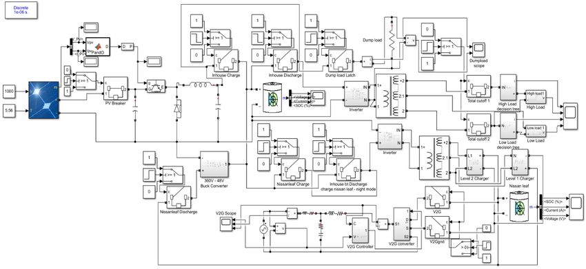
EJECE, European Journal of Electrical Engineering and Computer Science
 ISSN: 2736-5751

 I. Mode 8 – Nighttime Charging Mode = (1)
 +
 The power stored in the inhouse battery is used to charge
the Nissan Leaf's battery at night while the loads energy where, ω_c=corner frequency.
demand is much lower and the inhouse battery's SOC is
greater than 60% [17]. The control logic for nighttime level 1 = (2)
and level 2 charging mode is depicted in Fig. 21 and Fig. 22.

Switches S3, S4, S5, S8, S9 are switched ON to implement = (3)
 +
mode 8 at level 1 charging as seen in Fig. 21 and Table 1. In
mode 8 level 2 charging switches S3, S4, S6, S8, S9 are
switched ON as seen in Fig. 22 and Table I. = < −1 ( ) (4)
 √ 2 + 2

 = (5)

 = < −1 ( ) (6)
 √ 2 + 2 ω

 1
 = < −45 (7)
 √2

 1 1
 = × < −45 − 45 (8)
 √2 √2
 Fig. 22. Control logic for nighttime level 1 charging mode.
 1
 = < −90 (9)
 2

 Further to implement PLL, Vgrid and alpha signals are
 converter into DQ signals. A control system is set for Q
 output, the error between Q and Q ref is set as zero and is fed
 to a PI controller. The output from PI controller gives the
 angle information which is integrated to get ωt. Output from
 the Integrator is fed to alpha beta to DQ transformation block.
 In this case the output from PI controller is aligned with input
 signal. Hence this value can be used to generate active and
 Fig. 23. Control logic for nighttime level 2 charging mode.
 reactive current reference signal as seen in Fig. 25 [21], [22].
 The generated reference signal is added with grid voltage
 J. Mode 9 – V2G Mode which generates the reference signal for generation of PWM.
 In this mode the vehicle isolates itself from home and reels A unipolar generation scheme is implemented in the designed
power to the grid [18], [19]. Fig. 23 illustrates the control system. The reference voltage is compared with the triangular
logic for vehicle to grid (V2G) mode and Fig. 24 illustrates carrier wave and positive and negative references are
the vehicle to grid mode design in MATLAB. Switch S12 is compared. Output from each comparator is inverted and
switched ON to implement mode 9 as seen in Fig. 23 and connected to the gate terminal of each IGBT as seen in Fig.
Table I. The implemented design comprises of PLL block, 25. Fig. 26, 27, 28 illustrates the grid’s voltage graph, grid’s
Current controller (PI) and PWM generator [20]. Fig. 25 current graph and inverter current graph, respectively.
illustrates the implemented PI and PLL controller design.
PLL is used to generate a reference signal and the signal is in
phase with the actual voltage. The reference signal is used for
implementation of current controller in a grid connected
inverter. Further the Vgrid voltage is fed to a lowpass filter as
shown in equation 1 and Fig. 25. Substituting equation 2 in
equation 1 gives the transfer function in equation 3. The
magnitude and phase of lowpass filter can be in equation 4.
Assuming equation 5, ωc is replaced by ω in equation 6.
Further simplification results in equation 7. Adding a second
low pass filter as seen in equation 8, the magnitude becomes
1/2 and the angle would be -90 as seen in equation 9. Finally,
multiply the output from second low pass filter with 2 to get
an output signal (alpha) that is same as input with 90-degree
phase shift as seen in Fig. 25.
 Fig. 24. Control logic for vehicle to grid (V2G) mode.

 DOI: http://dx.doi.org/10.24018/ejece.2021.5.3.329 Vol 5 | Issue 3 | June 2021 50
EJECE, European Journal of Electrical Engineering and Computer Science
 ISSN: 2736-5751

 Fig. 25. Vehicle to Grid (V2G) mode design in MATLAB.

 Fig. 29. Inverter current graph – V2G mode.

 V. CONCLUSION
 For Newfoundland conditions, dynamic modelling of a
 solar energy system with vehicle to home and vehicle to grid
 options was successfully designed and simulated. The solar
 insolation for Newfoundland is 3.15 kWh/m 2/day, as seen in
 Fig. 1. The PV panels used are 340W modules that generate
 Fig. 26. V2G controller – PLL, PI controller.
 16.3984 kW and are configured in 24 strings, each with two
 panels. Nissan Leaf is configured as a deferrable load of
 9.90 kWh/d and 6.60 kW peak, a 12.5 kW commercially
 available inverter, 80 Trojan SAGM 12 105 batteries, each
 rated at 12 V and 100 Ah, a backup genset of 10 kW, and a
 vehicle to grid (V2G) inverter as seen in Fig. 7. In the
 simulation that has been implemented, there are nine main
 operating modes: i) inhouse battery charging mode – PV
 power is used to charge the inhouse battery while
 simultaneously powering the loads; ii) inhouse battery
 discharge mode – The stored power in the inhouse house
 battery is used to meet the loads energy demand; iii) Nissan
 Fig. 27. Grid voltage graph – V2G mode. Leaf charging mode – The available power is used to charge
 the Nissan Leaf after satisfying the load's energy demand and
 charging the in-house battery; iv) Nissan Leaf discharge
 mode: the loads have a high energy demand, but the PV and
 in-house battery SOC is low [23]. Nissan Leaf draws on its
 accumulated energy to meet the load's energy demand [24];
 v) in-house battery protection mode – avoids degenerative
 discharge of the in-house battery; vi) system isolation mode
 – prevents system failure; vii) excess power management
 mode – manages excess power generated; viii) nighttime
 charging mode – charges Nissan Leaf overnight in
 Fig. 28. Grid current graph – V2G mode.
 preparation for use the next day; ix) V2G mode – power is
 reeled to the grid. The system is scalable: it can be extended

DOI: http://dx.doi.org/10.24018/ejece.2021.5.3.329 Vol 5 | Issue 3 | June 2021 51
EJECE, European Journal of Electrical Engineering and Computer Science
 ISSN: 2736-5751

to include parking lots [25], several houses can be joined to [14] J. Gupta and B. Singh, "A Bidirectional Home Charging Solution for
 an Electric Vehicle," 2019 IEEE International Conference on
form a microgrid [26], and it can control or assist the grid Environment and Electrical Engineering and 2019 IEEE Industrial and
(V2G) [27]. The V2X model, in which vehicles are used to Commercial Power Systems Europe (EEEIC / I&CPS Europe), 2019,
schedule loads [28], power multiple homes, businesses, or an pp. 1-6, doi: 10.1109/EEEIC.2019.8783612.
 [15] V. Monteiro, B. Exposto, J. C. Ferreira and J. L. Afonso, "Improved
entire city, and transfer power from one vehicle to another
 Vehicle-to-Home (iV2H) Operation Mode: Experimental Analysis of
[29], will be studied further. [30]-[33]. the Electric Vehicle as Off-Line UPS," in IEEE Transactions on Smart
 Grid, vol. 8, no. 6, pp. 2702-2711, Nov. 2017, doi:
 10.1109/TSG.2016.2535337.
 [16] Y. Wang, O. Sheikh, B. Hu, C. Chu and R. Gadh, "Integration of
 ACKNOWLEDGMENT V2H/V2G hybrid system for demand response in distribution
 The authors acknowledge LUX Flavors PVT Ltd for network," 2014 IEEE International Conference on Smart Grid
 Communications (SmartGridComm), 2014, pp. 812-817, doi:
funding the research. 10.1109/SmartGridComm.2014.7007748.
 [17] H. Turker, "Optimal Charging of Plug-in Electric Vehicle (PEV) in
 Residential Area," 2018 IEEE Transportation Electrification
 Conference and Expo (ITEC), 2018, pp. 243-247, doi:
 REFERENCES 10.1109/ITEC.2018.8450125.
[1] R. Hemmati, H. Mehrjerdi, N. A. Al-Emadi and E. Rakhshani, "Mutual [18] H. Chtioui and G. Boukettaya, "Vehicle-to-Grid Management Strategy
 Vehicle-to-Home and Vehicle-to-Grid Operation Considering Solar- for Smart Grid Power Regulation," 2020 6th IEEE International Energy
 Load Uncertainty," 2019 2nd International Conference on Smart Grid Conference (ENERGYCon), 2020, pp. 988-993, doi:
 and Renewable Energy (SGRE), 2019, pp. 1-4, doi: 10.1109/ENERGYCon48941.2020.9236530. M.
 10.1109/SGRE46976.2019.9020685. [19] D. -C. Urcan and D. Bică, "Integrating and modeling the Vehicle to
[2] F. M. Shakeel and O. P. Malik, "Vehicle-To-Grid Technology in a Grid concept in Micro-Grids," 2019 International Conference on
 Micro-grid Using DC Fast Charging Architecture," 2019 IEEE ENERGY and ENVIRONMENT (CIEM), 2019, pp. 299-303, doi:
 Canadian Conference of Electrical and Computer Engineering 10.1109/CIEM46456.2019.8937610.
 (CCECE), 2019, pp. 1-4, doi: 10.1109/CCECE.2019.8861592. [20] A. K. Verma, B. Singh and D. T. Shahani, "Grid to vehicle and vehicle
[3] N. Z. Xu and C. Y. Chung, "Reliability Evaluation of Distribution to grid energy transfer using single-phase bidirectional AC-DC
 Systems Including Vehicle-to-Home and Vehicle-to-Grid," in IEEE converter and bidirectional DC-DC converter," 2011 International
 Transactions on Power Systems, vol. 31, no. 1, pp. 759-768, Jan. 2016, Conference on Energy, Automation and Signal, 2011, pp. 1-5, doi:
 doi: 10.1109/TPWRS.2015.2396524. 10.1109/ICEAS.2011.6147084.
[4] S. Rezaee, E. Farjah and B. Khorramdel, "Probabilistic Analysis of [21] Wooyoung Choi, Woongkul Lee, Di Han and B. Sarlioglu, "Shunt-
 Plug-In Electric Vehicles Impact on Electrical Grid Through Homes Series-Switched Multi-Functional Grid-Connected Inverter for
 and Parking Lots," in IEEE Transactions on Sustainable Energy, vol. Voltage Regulation in Vehicle-to-Grid Application," 2018 IEEE
 4, no. 4, pp. 1024-1033, Oct. 2013, doi: 10.1109/TSTE.2013.2264498. Transportation Electrification Conference and Expo (ITEC), 2018, pp.
 S. 961-965, doi: 10.1109/ITEC.2018.8450249.
[5] I. Sami Z. Ullah, K. Salman, I. Hussain, S.N. Ali, B. Khan, et al, "A [22] B. Rajalakshmi, U. Soumya and A. G. Kumar, "Vehicle to grid
 Bidirectional Interactive Electric Vehicles Operation Modes: Vehicle- bidirectional energy transfer: Grid synchronization using Hysteresis
 to-Grid (V2G) and Grid-to-Vehicle (G2V) Variations Within Smart Current Control," 2017 International Conference on Circuit,Power and
 Grid," 2019 International Conference on Engineering and Emerging Computing Technologies (ICCPCT), 2017, pp. 1-6, doi:
 Technologies (ICEET), 2019, pp. 1-6, doi: 10.1109/ICCPCT.2017.8074244.
 10.1109/CEET1.2019.8711822. N. [23] L. S. de Souza Pelegrino, M. L. Heldwein and G. Waltrich, "Low-
[6] H. Turker and I. Colak, "Multiobjective optimization of Grid- intrusion vehicle-to-home concept," 2016 International Conference on
 Photovoltaic- Electric Vehicle Hybrid system in Smart Building with Electrical Systems for Aircraft, Railway, Ship Propulsion and Road
 Vehicle-to-Grid (V2G) concept," 2018 7th International Conference on Vehicles & International Transportation Electrification Conference
 Renewable Energy Research and Applications (ICRERA), 2018, pp. (ESARS-ITEC), 2016, pp. 1-6, doi: 10.1109/ESARS-
 1477-1482, doi: 10.1109/ICRERA.2018.8567002. ITEC.2016.7841410.
[7] C. Liu, K. T. Chau, D. Wu and S. Gao, "Opportunities and Challenges [24] M. S. Shemami, S. M. Amrr, M. S. Alam and M. S. Jamil Asghar,
 of Vehicle-to-Home, Vehicle-to-Vehicle, and Vehicle-to-Grid "Reliable and Economy Modes of Operation for Electric Vehicle-to-
 Technologies," in Proceedings of the IEEE, vol. 101, no. 11, pp. 2409- Home (V2H) System," 2018 5th IEEE Uttar Pradesh Section
 2427, Nov. 2013, doi: 10.1109/JPROC.2013.2271951. International Conference on Electrical, Electronics and Computer
[8] Y. Wi, J. Lee and S. Joo, "Electric vehicle charging method for smart Engineering (UPCON), 2018, pp. 1-6, doi:
 homes/buildings with a photovoltaic system," in IEEE Transactions on 10.1109/UPCON.2018.8596932.
 Consumer Electronics, vol. 59, no. 2, pp. 323-328, May 2013, doi: [25] F. M. Shakeel and O. P. Malik, "Fuzzy Based Energy Management
 10.1109/TCE.2013.6531113. Y. System for a Micro-grid with a V2G Parking Lot," 2020 IEEE Electric
[9] B. Kim, "Smart charging architecture for between a plug-in electrical Power and Energy Conference (EPEC), 2020, pp. 1-5, doi:
 vehicle (PEV) and a smart home," 2013 International Conference on 10.1109/EPEC48502.2020.9320112.
 Connected Vehicles and Expo (ICCVE), 2013, pp. 306-307, doi: [26] J. Chen, Y. Zhang and W. Su, "An anonymous authentication scheme
 10.1109/ICCVE.2013.6799811. V. for plug-in electric vehicles joining to charging/discharging station in
[10] V. Monteiro, J. G. Pinto and J. L. Afonso, "Operation Modes for the vehicle-to-Grid (V2G) networks," in China Communications, vol. 12,
 Electric Vehicle in Smart Grids and Smart Homes: Present and no. 3, pp. 9-19, Mar. 2015, doi: 10.1109/CC.2015.7084359.
 Proposed Modes," in IEEE Transactions on Vehicular Technology, vol. [27] J. Guo, J. Yang and P. Ivry, "Development of an Intelligent Control
 65, no. 3, pp. 1007-1020, March 2016, doi: Platform for Vehicle-to-Grid Systems," 2020 9th International
 10.1109/TVT.2015.2481005. X. Conference on Renewable Energy Research and Application
[11] V. Monteiro, T. J. C. Sousa, C. Couto, J. S. Martins, A. A. N. Melendez (ICRERA), 2020, pp. 83-87, doi:
 and J. L. Afonso, "A Novel Multi-Objective Off-Board EV Charging 10.1109/ICRERA49962.2020.9242685.
 Station for Smart Homes," IECON 2018 - 44th Annual Conference of [28] N. K. Breum, M. N. Joergensen, C. A. Knudsen, L. B. Kristensen and
 the IEEE Industrial Electronics Society, 2018, pp. 1983-1988, doi: B. Yang, "A Charging Scheduling System for Electric Vehicles using
 10.1109/IECON.2018.8591325. Vehicle-to-Grid," 2019 20th IEEE International Conference on Mobile
[12] A. Ito, A. Kawashima, T. Suzuki, S. Inagaki, T. Yamaguchi and Z. Data Management (MDM), 2019, pp. 351-352, doi:
 Zhou, "Model Predictive Charging Control of In-Vehicle Batteries for 10.1109/MDM.2019.00-36.
 Home Energy Management Based on Vehicle State Prediction," in [29] S. Das, P. Acharjee and A. Bhattacharya, "Charging Scheduling of
 IEEE Transactions on Control Systems Technology, vol. 26, no. 1, pp. Electric Vehicle incorporating Grid-to-Vehicle (G2V) and Vehicle-to-
 51-64, Jan. 2018, doi: 10.1109/TCST.2017.2664727. V. Grid (V2G) technology in Smart-Grid," 2020 IEEE International
[13] J. G. Pinto et al., "Bidirectional battery charger with Grid-to-Vehicle, Conference on Power Electronics, Smart Grid and Renewable Energy
 Vehicle-to-Grid and Vehicle-to-Home technologies," IECON 2013 - (PESGRE2020), 2020, pp. 1-6, doi:
 39th Annual Conference of the IEEE Industrial Electronics Society, 10.1109/PESGRE45664.2020.9070489.
 2013, pp. 5934-5939, doi: 10.1109/IECON.2013.6700108. [30] M. Abul Masrur, Annette G, “Military-based Vehicle to Grid (V2G)
 and Vehicle to Vehicle (V2V) Microgrid - System Architecture and

 DOI: http://dx.doi.org/10.24018/ejece.2021.5.3.329 Vol 5 | Issue 3 | June 2021 52
EJECE, European Journal of Electrical Engineering and Computer Science
 ISSN: 2736-5751

 implementation” IEEE transaction on transportation Electrification
 PP(99(1-1), doi: 10.1109/TTE.2017.2779268.
[31] D. Guo, P. Yi, C. Zhou and J. Wang, "Optimal electric vehicle
 scheduling in smart home with V2H/V2G regulation," 2015 IEEE
 Innovative Smart Grid Technologies - Asia (ISGT ASIA), 2015, pp. 1-
 6, doi: 10.1109/ISGT-Asia.2015.7387135.
[32] A. Gautam, A. K. Verma and M. Srivastava, "A Novel Algorithm for
 Scheduling of Electric Vehicle Using Adaptive Load Forecasting with
 Vehicle-to-Grid Integration," 2019 8th International Conference on
 Power Systems (ICPS), 2019, pp. 1-6, doi:
 10.1109/ICPS48983.2019.9067702.
[33] M. Endo and K. Tanaka, "Evaluation of Storage Capacity of Electric
 Vehicles for Vehicle to Grid Considering Driver's Perspective," 2018
 IEEE International Conference on Environment and Electrical
 Engineering and 2018 IEEE Industrial and Commercial Power Systems
 Europe (EEEIC / I&CPS Europe), 2018, pp. 1-5, doi:
 10.1109/EEEIC.2018.8494218.

 Raghul Suraj Sundararajan (member IEEE) was
 born on 27th September 1995 in Coimbatore,
 TamilNadu, India. Completed his B.Tech degree in
 mechatronics engineering from SRMIST, Chennai,
 TamilNadu, India by 2017.
 He works as a teaching assistant and system
 designer at Memorial University of Newfoundland,
 St. John’s, Canada, and Dotndash, respectively.
 Presently, he is a graduate student and doing a
 research based M. Eng in electrical engineering.
 He has published conference papers on “Design of an IoT interface for a
 solar energy system with vehicle to home option for Newfoundland
 conditions” in IEEE IEMCON 2020, Canada, “Design of solar parking
 lot for 20 electric vehicles in St. John’s, NL” in IEEE NECEC 2020,
 Canada and “Dynamic simulation of an Isolated Solar Powered Charging
 Facility for 20 Electric Vehicles in St. John’s, Newfoundland” in IEEE
 NECEC 2020, Canada. Currently, his research focuses on the “Design of
 Vehicle to Grid energy system for Newfoundland conditions”.

 M. Tariq Iqbal received the B.Sc. (EE) degree
 from the University of Engineering and
 Technology, Lahore in 1986, the M.Sc. Nuclear
 Engineering degree from the Quaid-e-Azam
 University, Islamabad in 1988, and the Ph.D.
 degree in Electrical Engineering from the Imperial
 College London in 1994.
 Since 2001 he is working at the Faculty of
 Engineering and Applied Science, Memorial
 University of Newfoundland. Presently he is full
 Professor. His teaching activities cover a range electrical engineering
 topic, including renewable energy systems and power electronics.
 Currently, his research focuses on modeling and control of hybrid energy
 system.

 DOI: http://dx.doi.org/10.24018/ejece.2021.5.3.329 Vol 5 | Issue 3 | June 2021 53
You can also read