Energy Recovery Wheel - OPERATION AND MAINTENANCE VERSION 3.0.0 - Swiss Rotors
←
→
Page content transcription
If your browser does not render page correctly, please read the page content below
Energy
          Recovery
          Wheel
          OPERATION AND
          MAINTENANCE
          VERSION 3.0.0

www.swissrotors.com       1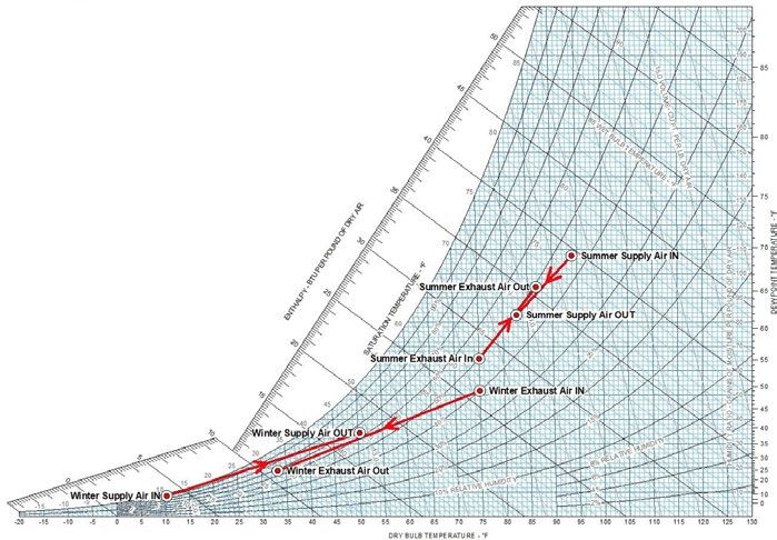
Please read the following documentation carefully before performing installation, maintenance
and operating of Swiss Rotors rotary heat exchangers motors. In case of doubts contact Swiss
Rotors official support. This manual must only be used by a qualified installer/service technician.

TABLE OF CONTENT

PLEASE READ BEFORE PROCEEDING.....................................................................................................3
1. INTRODUCTION.....................................................................................................................................4
1.1 Preface................................................................................................................................................4
1.2 Disclaimer...........................................................................................................................................4
2. PRODUCT DESCRIPTION......................................................................................................................4
2.1 Construction.......................................................................................................................................4
2.2 Serial number identification...............................................................................................................7
3.TRANSPORTATION................................................................................................................................9
3.1 Packing..............................................................................................................................................9
3.2 At delivery...........................................................................................................................................9
3.3 Lifting..................................................................................................................................................10
3.4 Moving at site.....................................................................................................................................10
3.5 Storage............................................................................................................................................... 10
4. INSTALLATION......................................................................................................................................11
4.1 Pre-installation assumptions.............................................................................................................11
4.2 Motor connection................................................................................................................................11
4.3 Purge Sector installation..................................................................................................................13
4.4 Profile Adapter Installation...............................................................................................................15
5. BEFORE START-UP..............................................................................................................................15
5.1 Start-up checklist..............................................................................................................................16
6. MAINTENANCE...................................................................................................................................16
6.1 Safety ...............................................................................................................................................16
6.2 Energy Recovery Wheel....................................................................................................................16
6.3 Energy wheel maintenance & cleaning............................................................................................18
6.4 Drive Belt – maintenance & replacement........................................................................................18
6.5 Sealing system..................................................................................................................................21
6.6 Brush Plate........................................................................................................................................22
6.7 Purge Sector......................................................................................................................................22
7. FROST CONTROL ..............................................................................................................................22
8. SPARE PARTS......................................................................................................................................25
9. SUPPORT.............................................................................................................................................25

                                                                                                                                                             2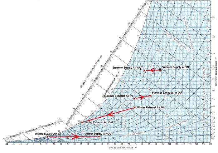
PLEASE READ BEFORE PROCEEDING
       Installer – Read all instructions, including this manual, before installing. Perform steps in
       the order given.

       When calling or writing about the recovery wheel – Please have the model and serial
       number from the rating plate. Any claims for damage or shortage in shipment must be
       filed immediately against the transportation company by the consignee. Factory warranty
       (shipped with unit) does not apply to units improperly installed or improperly operated.

       Failure to adhere to the guidelines on this page can result in severe personal injury, death,
       or substantial property damage

       If the information in this manual is not followed exactly it could result personal injury,
       death or substantial property damage.

       Do not connect the device to the power supply before getting familiar with this manual.
       Installation procedures should be carried out by qualified personnel.

                                                                                                   3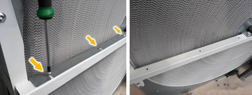
1. INTRODUCTION
1.1 Preface
To ensure trouble-free usage of our products we would like to provide the following technical and
commissioning documentation. This manual is to help at every stage of use. Mandatory maintenance
service tasks that are responsibility of the user, from appropriate transportation methods to periodic
inspections. All the crucial information and warnings will be preceded by various caution symbols
as shown below:

		            Health Safety Warnings

		            Electrical Safety Warnings

		            Important Information

		            Useful Hint

Please read carefully the entire user manual and all other accompanying documents before first
start-up. Keep it as a reference for future maintenance and service procedures.
1.2 Disclaimer
The following instruction, unless otherwise stated, applies to all Swiss Rotors energy recovery
wheels. In exceptional circumstances, differences will be noted. This document is a property of
Swiss Rotors, licensors or affiliates, protected by international trademark and copyright laws. Swiss
Rotors constantly develops its products and this document is subject to change without notice.

2. PRODUCT DESCRIPTION

2.1 Construction
Swiss Rotors produces two series of rotary heat exchangers in two standard widths of energy
recovery wheels: SF series with 100 mm and RT with 200 mm depth recovery wheel. This manual
applies to the SF series of heat exchangers. Please be aware that versions may differ from each
other by their components, parts location, dimensions, auxiliary equipment and motor types. Most
of the construction elements are maintenance-free, while those that require periodical inspection
are listed in the Maintenance section of this manual. To ensure a long-term operation, carefully read
the instructions and follow the given time control intervals.

                                                                                                     4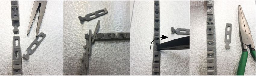
Figure 2 Swiss Rotors SF series rotary heat exchanger with 4 in width energy recovery wheel

                                                                                              5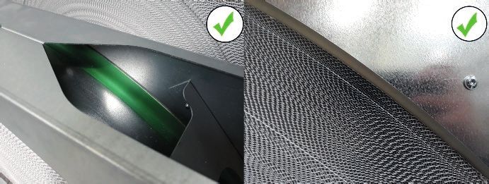
Wheel Type                    Wheel Code                 Construction                          Recovery Type
Enthalpy                                               Monolith energy recovery wheel. Both         Latent and sensible heat.
(S-Sorption wheel)                                     layers of 3A molecular sieve coated         Whole area of matrix takes
                                             T                      aluminium.                     part in latent heat recovery.
                                                                                                   Fast moisture recovery and
                                                                                                    antimicrobial properties.
S-Sorption wheel                            NH          Monolith energy recovery wheel with    Sensible heat and moderate
(C-Condensation wheel)                                  uncoated layers of aluminium only.           latent recovery.

   Table 2.1. Swiss Rotors SF, RT series rotary heat exchanger with 100 and 200mm width energy recovery wheel

                                        Wheel hub of an heat exchangers are made of extruded aluminium, diameter
                                        of 150 mm or 250 mm respectively, depending on an overall diameter of energy recovery
                                        wheel. For energy recovery wheels of diameters exceeding 1200 mm, hub is reinforced
                                        with additional 500 mm spokes to reduce torque and eliminate material fatigue.
                                        Bearings are permanently sealed and lubricated, therefore require no maintenance.

                                        Swiss Rotors rotary heat exchangers, depending on the model may be equipped with
                                        various stepper motors. For more motor-related information’s please refer to the motor
                                        instruction.
Figure. 2.2 Hub, shaft and bearing of
       rotary heat exchanger

                       Model                  Wheel            WxHxD [in]              AIRFLOW
                                           Diameter[in]                             min/max[SCFM]
                       SF-21                      22             24x24x4.5              215-1200
                       SF-27                      27             29x29x4.5              330-1800
                       SF-32                      32             34x34x4.5              540-2710
                       SF-37                      37             40x40x4.5              770-3840
                       SF-42                      42             44x44x4.5              960-4780
                       SF-48                      48             50x50x4.5             1260-6310
                       SF-54                      54             56x56x4.5             1620-8080

                       SF-60                      60             62x62x4.5            2030-10130
                       SF-66                      66             68x68x4.5            2420-12110

                       SF-70                      70             72x72x4.5            2740-13710

                       SF-76                      76             78x78x4.5            3240-16200

                       SF-83                      83             85x85x4.5            3650-17800

                                                 Table 2.3. Range of SF products available

                                                                                                                                   6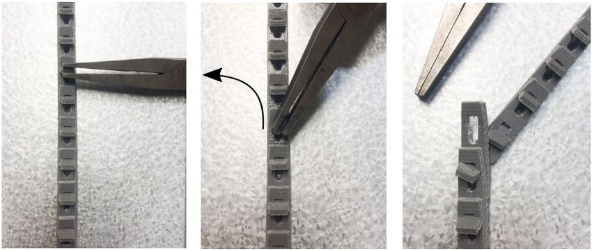
2.2 Serial number identification

Each product leaving our factory is equipped with a label plate containing product identification data. Labels are
attached directly on the casing and provides essential information’s about the product. Fig. 3 shows the exact location
of the label plate. Take a note of the possibility that label plate design may be changed and look different depending
on the destination market. Despite slight visual differences, serial number will always remain in the same visible area.

                                          Figure 2.4. Identification label plate location

Each identification label contains following pieces of information: model, dimensions, type of motor, type of rotary
wheel, type of controller, individual serial number. Using serial number for product identification is the fastest and most
accurate method. By serial number we are able to identify your product and answer your question effectively. It will also
allow for the proper spare parts selection in case they need to be replaced. While contacting our company make sure
to have your serial number in sight.

Additionally, each Rotary Heat Exchanger is labelled with dedicated stickers providing the user and installer with the
most necessary on-site information. Stickers indicating the spinning direction of the rotary heat exchanger wheel allows
to install the unit in the correct orientation .

                                                                                                                          7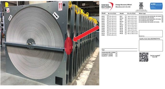
Figure 2.5. Additional labels on SF Rotary Heat Exchangers

                                                             8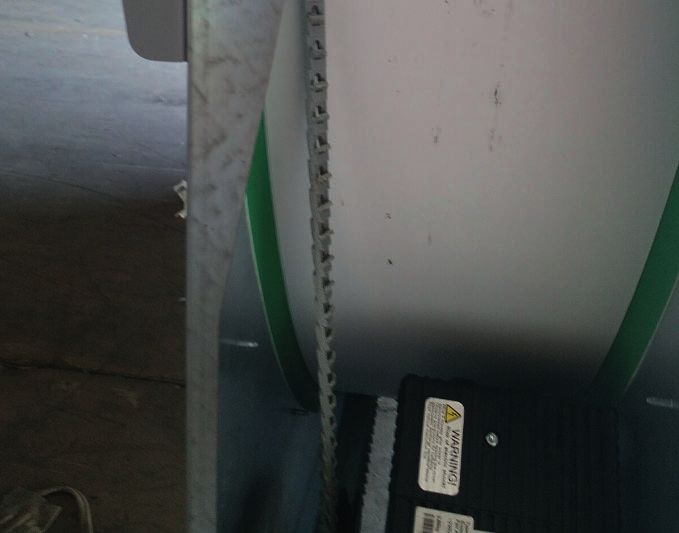
3. TRANSPORTATION
3.1 Packing
Swiss Rotors energy recovery wheels are sent on either wooden
pallets or transportation supports, sealed against weather
conditions, attached and strapped to prevent tilting. Wheel matrix
is additionally protected with cardboard and stretch foil to protect
from accidental scratches or punctures. Each heat exchangers
are equipped with additional leaning label.
SF heat series wheels are placed and tightly strapped to wooden
pallets, per MOQ. Transportation supports can withstand the
weight of the exchanger and prevent tilting to facilitate safe
transportation.
Wheels are covered with additional layer of carboard material to
                                                                     Figure 3.1 Swiss Rotors – packing of heat exchanger
Individual shipments may be packed in wooden casings with
wheel matrix protected by additional flakeboard layer.

          To avoid dents or scratches on the wheel surface please make sure to properly secure the package for the
          further transportation.

3.2 At delivery

Each heat exchanger is equipped with special Leaning Label (Fig.
4) identifying whether the goods were transported in an appropriate
manner. Balls inside the contoured channels will help visualize the
method of transportation and whether the package was subjected to
undesirable tilting. Pay attention to the warranty sealing sticker of the
label – each leaning label is additionally taped with warranty seal before
shipment. Warranty is void if the warranty seal is broken or missing.

At the time of delivery, you should do the following:
• Check the condition of the package carefully in the presence of
    a shipping company representative before delivered parcel will
    be accepted. Look for any signs of transportation damage. Our
    rotary heat exchangers are precisely and tightly secured for the     Figure 3.2 Leaning label with warranty seal atta-
    shipment. There should not be any signs of tearing on the surface ched to the casing of rotary heat exchanger.
    of the package, punctures, exposed elements or traces of opening.
• Pay attention to the way in which the goods were delivered. Check the leaning label and its warranty seal
    sticker. Rotary exchangers can only be shipped in a vertical position. Any other way of arranging the package is
    unacceptable. Pay attention to whether the shipment is delivered on a pallet or it has been dismantled without
    permission.
• Swiss Rotors prepare shipments using professional labels and transport descriptions. If you see that the shipping
    company did not followed the instructions given on the package - refuse to accept the parcel.
• Check if the received parcel matches with your order. Inspect the product label plate for confirmation.
• In case of any damage please contact our support immediately - phone numbers are listed at the Contact chapter
    of this guidebook or at our official website: www.swissrotors.com.

                                                                                                                             9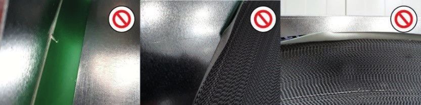
Be especially careful when unpacking the exchanger. Energy Rotary Wheels can be transported only in a vertical
position. They cannot be stacked on top of each other. While unfastening the transportation straps, make sure that
the exchanger will not flip over. Use protective gloves – elements of the heat exchanger may have sharp edges or be
covered with the iron oxide, resulting from the material characteristics (which is completely natural – do not affect
the quality of the product.)

3.3 Lifting
                                        To avoid damages and serious accidents, lift the
                                        exchanger as shown on the following illustrations
                                        and follow given instructions. Any other methods
                                        of lifting the exchanger may result in its serious
                                        damages or injuries. All the transportation tasks
                                        should be carried out by qualified staff. Use
                                        protective clothing and make sure no one is in the
                                        range of movement of the exchanger. Extreme
                                        precautions should be taken.

                                 Swiss Rotors wheel are equipped with the
                                 special lifting straps (Fig. 5) attached on the both
Figure 3.3 Transportation straps
                                 sides of the casing. They are already tied to the
                                 transportation holes on both sides of the upper
casing of an exchanger and are designed particularly for the lifting purposes. Any
other method of lifting is prohibited.

                                                                                                     Figure 3.4 recovery wheel

                                        Transportation straps provided are adapted
                                        to the weight of the exchanger and cannot be
                                        replaced. If for some reason transportation belts
                                        have not been attached at the top of your rotary
                                        heat exchanger - contact Swiss Rotors support.
                                        Remove the belts after installation.

                                        Attach transportation hooks to both belts (Fig. 7).
                                        Use hooks with additional safety clips to prevent
                                        accidental fall. Make sure your hooks with belts
                                                                                              Figure 3.6 Force distributed in the
Figure 3.5 Hooks properly attached to   are adapted to lift the weight of the exchanger.      middle of the lifted exchanger
      the transportation straps
                                 Use only professional transport utility.
Ensure an even weight distribution by lifting the belts centrally, at the middle of the heat exchanger (Fig. 8). Any retraction
from the centre of the exchanger axis may cause the exchanger to tilt and unclip from the belts. Make sure that your
lifting device can withstand the weight of the exchanger.

3.4 Moving at site

In order to move the heat wheel properly and safely, use pallet track or forklift (Fig. 6). Use the pallet track carefully by
driving slowly without making any sudden movements. Disassemble transportation blocks (one at the time) once the
heat exchanger reach the destination and will be finally ready for the installation inside a unit.

3.5 Storage

If the exchanger is not installed immediately, leave the product in its original packaging and follow the rules of proper
storage. Prolonged exposure of the product to the improper conditions may damage and shorten the lifetime of vario-
us rotary heat exchanger components.

                                                                                                                                    10
• Avoid exposure to moisture, excessive sunlight and other weather conditions.
• Make sure the rotary heat exchanger is positioned vertically on the dry and flat ground. Long-term storage on
curved floor may cause tilting of energy recovery wheel and seriously affect the factory pre-calibration. In extreme
cases, warped wheel may scrub the interior of the casing and force the user to perform additional adjustments.
• Support and secure the exchanger against mechanical damages.
• Keep the storage temperature between 32°F and 89.6°F
• Do not stack exchangers on top of each other. Each product needs to be placed separately.
4. INSTALLATION
The following section contains valuable notes and list of mandatory procedures which are responsibility of the user.
Neglecting advices collected in this chapter may result in product damage, void of warranty or even health loss. Take
time to study carefully whole chapter and make sure everything is understandable. If you have any questions, please
contact support. For more information regarding motors and controllers detailed information please see the Step
Motor Manual.
4.1 Pre-installation assumptions
Do not connect the device to the power supply before getting familiar with this manual.Installation
procedures should be carried out by qualified personnel.
Swiss Rotors heat wheels are designed to work only and exclusively inside the air handling unit. Rotary Heat
Exchangers should not be forced to work outside of the AHU or other closed systems. Their desired work
environment is the interior of the ventilation devices. The only justified reason for device extraction could be
completing maintenance tasks such as cleaning, disinfection of wheel or performing annual controls
(only if it is necessary).
Be sure that channels inside the ventilation unit divides rotary heat exchanger at the centre of their energy
recovery wheel matrix. Profile should divide and separate counter flowing air channels. Make sure that the
air handling unit channels will supply the air to the exchanger evenly. For horizontal installation it is necessary
to apply centre support beneath the wheel. Secure the unit ducts and area below the desired installation
location from falling.
Exchanger need to be installed in a way enabling seamless execution of future maintenance tasks. AHU
designer needs to anticipate the necessity of easy access for performing basic maintenance procedures.
Rotary heat exchangers require periodic service tasks which should not be limited by lack of access. Each
component of exchanger should be easily reachable.
• Install the exchanger so that is possible to pull it out of the ventilation unit easily in case of any failure.
• Ensure easy access to the motor.
• Make sure there is an easy access to both sides of the rotary heat exchanger.
• If there is a possibility of liquefying condensate occurrence - prepare the floor for such event or place the
dedicated condensation tray underneath energy recovery wheel.
• Make sure the rotary heat exchanger is firmly attached inside the ventilation system and will not move or oscillate
inside AHU wile fans will start causing the air movement to push against matrix of the energy recovery wheel.
4.2 Motor connection
Depending on the diameter of the wheel inside the rotary heat exchangers, SF and RT series comes with three stepper
motor types matched with the desired parameters. Following notes are quick guidelines concerning motors used in our
products to help with the smooth start-up. For more advanced and detailed instructions, please refer to the separate
motor manual provided with the exchanger.
Motors can be connected, installed, modified and maintained only by professional staff, per local electrical
code. Incorrect installation can cause damage and risk of fatal injuries from electric shock!
For more detailed information please see the Step Motor Manual.
Before connecting the motor, ensure that the supply voltage matches the operating voltage of the device.
11• Use only cables that are designed for current according to the specification on the motor label plate.
• Connect the device only to the circuits that can be switched off using an all pole disconnecting switch.
• Use fuses at power lines. Install all ground wires. Before operating, check the wires for short circuits. Use only
cables that meet the specified installation requirements for voltage, current, insulation material, load etc.
• To avoid high voltage shock, disconnect main supply voltage and wait at least 3 minutes before operating and
maintaining motor.
• It is the responsibility of the user/installer to ensure correct grounding and system protection in accordance with
the national and local standards.
• Use only hard wire or fibre copper wire with ferrule. To reduce operating problems, use a shield cable. Cables should
be as short as possible. Please refer to motor manual for appropriate cable lengths.
• Wrong connection could cause fatal damage of the controller and other devices connected to the controller.
Damaged terminal strips can cause fatal damage of the controller and can cause fatal injury from electric shock.
•
EC motors are equipped with thermal protection. This function is a temperature limiter which reduces the output power
when temperature on the controller rises over 90°C. In case in which temperature of controller is still rising (over 105°C)
the controller will automatically stop the motor. When the controller temperature will fall below 75°C, the motor will be
automatically restarted.
Motors are assembled, pre-set- it is forbidden to interfere in the assembly of the motor and gear without
previous arrangements with the manufacturer or Swiss Rotors service support. All motors are pre-set for
desired constant RPM of wheel. If rotation control is required, either use EC motor with integrated rotation
controls, or use AC motors with external controller or frequency inverter. Motor should be easily reachable.
To avoid overheating, ensure that cooling inlet of the motor is clear and not blocked in any way and motor
is not located on the outside air side of the wheel.
Swiss Rotors motors warranty applies only when:
Power supply connection and wiring was carried out correctly according to given documentation. Motor and related
components have no marks of dissembling nor modification. Electrical connection was carried out in accordance to
local regulations. Swiss Rotors is not responsible for any damage resulting from wrong installation.
124.3 Purge Sector installation
Swiss Rotors energy recovery wheel comes with two additional purge sectors. Their task is to exclude exhaust air carry
over into supply air stream which occurs during rotation of the wheel matrix. It is an optional element and may not
be needed based on application. The advantage of using sectors is also an increased ability of the rotor wheel self-
cleaning. Start by determining the proper mounting position of the purge sectors in your heat exchanger. Depending on
airflow configuration and wheel rotation direction, please choose the proper mounting position. Sector can be located
on the side of fresh air supply only and exclusively.
Bearing in mind the airflow and rotation direction of the rotary wheel, please refer to the following illustrations presenting
possible ways of proper purge sector installation.
Figure 4.1 Position of purge sector
Reverse assembly is incorrect and will cause the sector to block the fresh air inlet instead of preventing airstream
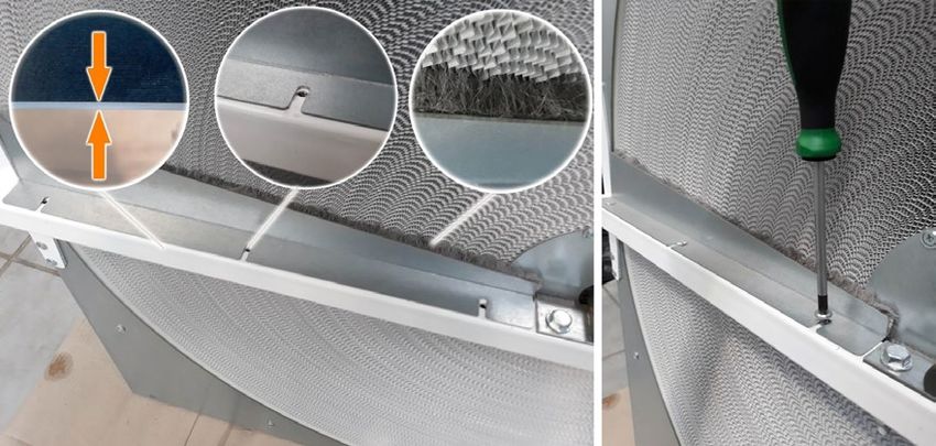
mixing. To install purge sector follow instructions below:
1. Detach brush plate from the profile starting with unscrewing the screws. Purge sector is equipped with brush and
will fully replace the standard brush preassembled to the central bar. Use the appropriate screwdriver with T25 bit to
unscrew the connections.
13Figure 4.2 Unscrewing the screws in brush plate
2. Install the purge sector and match its cutaways with the mounting holes on the profile. They
should line up. Position the sector so that the brush is in gentle contact with the surface of the rotary
wheel. Purge sectors cannot scratch the surface of the rotary wheel. Keep the proper distance to
prevent failures. Firmly attach the purge sector to the profile with the previously unscrewed mounting
screws cannot scratch the surface of the rotary wheel. Keep the proper distance to prevent failures.
Firmly attach the purge sector to the profile with the previously unscrewed mounting screws.
Figure 4.3. Installation of the purge sector.
144.4 Profile Adapter Installation
Installation of the optional profile adapter needs to be performed right after the installation of purge sector. Reverse
order will not allow the access needed for the purge sector assembly.
• Attach the profile adapter to match the holes located on the
horizontal profile. Holes should line up. Depending on set-inc-
luded fasteners attach the profile adapter with screws or rivets
provided. Appropriate number of connectors needed for the pur-
pose of the installation is included in the set.
Figure 4.4 Installation of the masking plate
5. BEFORE START-UP
Before performing first start-up, check the mechanical condition of the individual components of delivered product. As
a result of inappropriate transport or storage you may have to check construction parts of the product (see appropriate
Maintenance chapter). If the exchanger was transported and stored in a proper condition, Swiss Rotors products comes
fully calibrated and assembled in a way which does not require any additional installation tasks from the user. All
components of our products are brand new and should not wear signs of usage or mechanical damage.
• Crucial screw connections should be sealed and marked with paint - make sure the seals are not violated. If you
suspect damage to the product, please contact our support immediately (Fig. 9).
• Check for any unwanted objects inside the casing which are not construction related. There should not be any
obstacles that prevents smooth rotation of the wheel. Check whether it is possible to rotate the wheel freely by
turning it manually. It should be possible to rotate the wheel with your bare hand.
• While turning the wheel, pay attention to whether the exchanger generates any unnecessary metal sounds or rubs
against the casing parts. The only acceptable noises should be generated by brushes and sealing which are in direct
contact with the casing and wheel surface.
• Inspect condition of sealing and brushes. Swiss Rotors wheels come with non-contact sealing covering whole
periphery of the wheel. Sealing is attached directly to the wheel surface and spins adhering to the exchangers
casing. The subtle shuffling sound of sealing (and brush) is acceptable and normal. Sealing and brushes do not
• Verify the appropriate tension of the drive belt (belt cannot slide). Check the visual condition of the belt all along
the wheel. Adjust if necessary. Instructions concerning tension settings can be
found in Maintenance chapter. Belt should pass freely through the pulley and
adhere to the surface of the wheel passing on top of additionally placed belt
tooth located on the surface of wheel without encountering any obstacles inside
the housing.
• If it is possible - perform the first start outside the AHU in order to avoid
inequality of airflow forces caused by fans.
Make sure that an appropriate electrical installation is on site.
Depending on the model, Swiss Rotors rotary heat exchangers require
specific power supply. Please refer directly to the motor manual before Figure 5.1 Sealed elements
performing connection to the power supply. All electrical wiring and
connections should be carried out by qualified staff, depending on
electrical code and other regulations that may apply, depending on
particular jurisdiction. There is a risk of fatal injury resulting from
performing incorrect installation.
155.1 Start-up checklist
Please refer to the following table containing most important things user should check before performing first start-
-up:
Inspect tasks Check
Exchangers was delivered in a perfect condition, without missing parts and with sealed screw con-
nections.
Exchanger outer dimensions fit the place intended for installations inside the AHU.
AHU is ready and tailored for the installation of rotary heat exchanger.
There are no unwanted objects or obstacles inside the casing of the exchanger.
Wheel spins freely inside the casing and is not scratched or damaged at any place.
Drive belt is placed and tightened properly on the pulley and wheel.
Current with the appropriate parameters specified in the motor manual is provided on site.
Motor is connected accordingly to its manual schematics.
Purge sector was installed properly and rigidly.
If all the requirements listed above are met, you can start the first run. For the first 15 minutes of operation, you should
carefully observe the components and make sure that the installation has been carried out successfully. Pay attention
to all moving components. The motor should run evenly without rotation fluctuations and without excessive heat rele-
ase. Make sure the purge sector is installed in the right position, depending on airflow.
Check the wheel as often as possible for the first 12 hours. Standard inspection intervals are described in the follo-
wing Maintenance chapter.
6. MAINTENANCE
6.1 Safety
Fully disconnect the device from the power supply before carrying out any service operations. All electrical
work should be carried out by qualified staff only. Incorrect electrical connection can result in fatal injuries
or product damage.
Do not touch any moving parts inside the rotary heat exchanger. While performing any service tasks remem-
ber to use protective gloves. Turn of the whole HVAC system before performing any servicing operations.
6.2 Energy Recovery Wheel
Swiss Rotors strongly recommend checking the condition of individual components according to the time table provided
in this chapter. Technical control is obliged to the user. Properly frequent checks allow early detection of irregularities in
the system and may help avoiding serious damages resulting from various random factors. Please refer to our general
proposed inspection checklist and timetable presented below. Some inspection operations cannot be carried out
when the exchanger is disconnected and does not work. Therefore, if possible, check the components during normal
exchanger operation and again after disconnecting from the power supply.
Remember to keep precautions while performing checks on working exchanger - do not touch moving parts under
any circumstances.
16Verify OK
Wheel of the exchanger spins smoothly without making unwanted noises or rubbing against internal
parts.
Wheel of the exchanger is free of mechanical damage. There are no traces of rust.
Wheel of the exchanger is not excessively dirty or clogged. Airflow is not blocked by impurities.
Wheel of the exchanger is parallel to the surface of the casing walls and do not tilt in any direction.
Drive belt is free of mechanical damages - no damage traces along the entire length.
Belt adheres perfectly to the motor pulley - there is no skipping or loses.
Belt is properly positioned on the entire length of the exchanger - not twisted or flipped at any point.
Tension of the belt is not too loose - no deviation from the axis of adhesion.
Sealing of the wheel is tight on the whole circumference of the wheel.
Sealing is not rolled up or punctured.
There are no visible signs of loose connections on the entire heat exchanger.
Casing is firmly attached to the AHU - exchanger does not move unintentionally inside the system.
Motor works smoothly - without skipping, overheating, pauses or generating unwanted noises.
There are no unwanted objects inside the casing which are not internal exchangers parts.
Obligatory Inspection Time Intervals
First 12 hours First 24 hours First week Every year Every two years
Wheel matrix ● ●
Belt ● ● ●
Pulley ●
Casing ●
Sealing
Brushes ● ●
Purge Sector ● ● ●
Motor According to the separate operation and maintenance manual of motor installed in exchanger.
176.3 Energy wheel maintenance & cleaning
Depending on the working environment maintenance tasks must be carried out at various time intervals. Frequency
depends on the quality of the air distributed to the energy wheel matrix. It may turn out that self-cleaning effectiveness
is insufficient in given work environment and some manual cleaning will be necessary. Basing on the ASHRAE Standard
62.1 guidelines, please refer to the following list separating the air classes in terms of their pollution.
Air Class Contamination description Cleaning Pre-Filtration Class
Frequency PN-EN 779
(MINIMUM EFFICIENCY
REPORTING VALUE)
Class 1 Average clean air consisted of low contamination. Every 8 years G4
Non-odorous and free of toxic fumes. May be found
in office spaces, class rooms, meeting places like
conference rooms, lecture halls, churches.
Class 2 Moderately contaminated air. Mildly sensory- Every 4 years M5-M6
irritating. Slightly offensive odours: swimming
pools, restrooms, restaurants, magazines and
warehouses, cloakrooms.
Class 3 Air of significant contamination concentration with Every 1-2 years F7-F9
offensive odours. Marked irritation of the senses
may be felt. Depending on the activities this may
apply to laboratories, hospitals, production areas
involving material processing, shopping centres etc.
Class 4 Highly contaminated air which may be dangerous Swiss Rotors energy recovery wheels are not suita-
for health. Odorous and irritating environment. ble for application in such work environment
Painting shops, processing of harmful materials,
laboratories working with toxic compounds
Swiss Rotors recovery wheels cannot be used in highly polluted areas including kitchens: use may cause
an explosion. Expose to air containing oil, aerosols, VOCs will cause the contamination to build upon the
energy wheel surface causing clogging of the air channels.
Swiss Rotors recommends following methods of cleaning:
• Brush cleaner or vacuum cleaner for small amount of dust deposit which is easy to remove
• Air compressor burst. Use precaution with keeping an appropriate distance between matrix and compressor nozzle.
Too much pressure can easily damage the aluminium media. Try to keep the minimum distance of 60 mm from the
wheel.
• Water burst from the appropriate distance of minimum 60 mm from the surface of the energy recovery wheel ma-
trix. Do not use any detergents! Keep temperature below 25°C. Tightly cover all electric parts and bearings while
using pressure water streams.
During manufacturing process there is a chance that some of surplus coating material will remain on the wheel. In such
wheels there is a high probability that surplus material will leave the matrix (especially after first few hours of operation).
This phenomenon is natural and do not affect the efficiency or adsorption properties of the of exchanger in any way.
Use vacuum cleaner to get rid of the surplus material from the surface of the wheel after first 24hour of operating. This
molecular sieve should not be inhaled, SDS of coating is available upon request.
Note that energy recovery wheels are not meant to operate in environment of toxic, flammable or corrosive fumes, or
special application exposed to corrosive / industrial processes or marine environment, exposure to liquid water, paint,
dust or grease from commercial kitchen, for further application guidance contact Seller’s representative.
6.4 Drive Belt – maintenance & replacement
Drive belt requires periodic inspections. Due to material property, belt may stretch, therefore it may require user
to increase the tension, upon inspection.
Obligatorily check the tension after first 24h of the operation and at least once a year while doing general control.
18If segmented drive belt becomes too loose it is necessary to pull out few
segment modules (Fig. 10) of the belt and shorten their overall length to
desired amount in order to achieve optimal tension. Correct tension should
prevent ability to insert anything underneath the belt on the entire length of
the tangent between the belt and the wheel. Belt cannot slip. Performing
annual maintenance service - inspect the visual condition of the belt all along
the wheel. Be sure that belt is not wearing any signs of mechanical damage.
Check the convergence on the wheel pulley. Any losses are not allowed and
Figure 6.4 Segments of belt used in Rotary Heat
may cause belt skipping on the pulley of the motor. The belt should pass freely Exchangers
without encountering any obstacles inside the housing.
Because of the segmented drive belt construction – in case of any failure there is no point in replacing the entire
drive belt. Replacing individual segments is enough to restore its functionality. Please follow the instructions below,
presenting proper way of replacing segments or increasing belt tension.
Figure 6.5 Disconnecting of the belt
Unclip the belt using pliers. Grab the protruding tongue of the segment to remove and twist it to release the segment
from the chain. Disconnect the belt in that place.
Figure 6.6 Adding or removing new segments of the belt to change the overall belt length
Remove the desired amount of segments to increase the belt tension. Connect the shortened belt ends with each
other by inserting the protruding tongue through the hole of the other half of the belt. Grab the second tongue and
similarly insert it through the second hole – this time use the pliers to drag the segment tongue easier and twist it
back to the starting position. Your belt is now shortened and the tension of the belt is increased.
If for some reason there is a need to completely replace the segmented belt, start with measuring the proper length
of the new belt. Due to its extensibility, measure the exact length of energy recovery wheel circumference. Put the belt
inside the casing and encircle the circumference of the energy wheel. Even if the length of the belt seems too short,
stretch it and connect two of their ends near the pulley and transmission shaft using pliers. Having the belt clipped
together – stretch the belt with force once again to put it on the pulley wheel.
19Flat side of the belt (the one without the connecting pins protruding outwards) needs to be in direct con-
tact with the rotary wheel along the entire circumference of their contact to drive the heat exchanger cor-
rectly. The opposite side of the belt should be in contact with the inner surface/grove of the pulley wheel
of the motor. To obtain such arrangement belt will rotate towards the motor (see Fig. 6.8). Make sure that
the belt is installed in the right manner. Fig 6.7 presents the properly arranged belt inside the rotary heat
exchanger. Take a note that the flat surface of the belt as well as the proper rotation direction of the belt is
indicated by the small arrow visible on the belt itself .
Figure. 6.7 Correct belt arrangement
Figure. 6.8 Belt twisting towards the motor pulley wheel
Recovery wheel rotation direction is always towards the motor (top to bottom)
206.5 Sealing system
Both non-contact sealing on wheel peripheries and brush sealing middle beam are maintenance-free but their con-
dition must be checked every year. During the inspection, check their tightness and overall visual condition. Non-con-
tact seals cannot be flipped, rolled or pierced at any place (Fig. 6.8, Fig. 6.9).
Figure 6.9 Correctly fitted sealing of the Rotary Heat Exchanger.
Swiss Rotors wheels are equipped with durable sealings which should last lifespan of the entire product if properly
used and maintained. If sealings are damaged, please contact our service immediately. A damaged seal may cause
efficiency deterioration, mixing of an air flows and unwanted leakages in the system, especially in environment with
hygienic requirements.
Figure 6.10 Examples of broken and incorrectly fitted sealings.
To install the new sealing, it is obligatory to start with cutting off the old sealing with sharp knife all along the circum-
ference of the energy recovery wheel (Fig. 14). Try to cut the sealing as close to the recovery wheel matrix as possible.
Don’t use force, don’t pull the sealing, do not damage the matrix of the recovery wheel – caution must be preserved.
21Figure 6.11 Cut the old sealing. Figure 6.12 Use tacker to staple the Figure 6.13 Put the aluminium
new sealing all around wheel circum- reinforced tape at the top of new
ference. sealing and wheel surface.
Place the new sealing so the protruding amount of material will cover the gap between the energy recovery wheel
and casing wall. Properly positioned sealing must be sawn with the tacker to the top of the energy recovery wheel
all around it’s circumference (Fig. 15). Place the tacker staples at the distance of about 7.87 in from each other all
around the circumference of the energy wheel. Before starting up the operation of energy recovery wheel with the new
sealing system – check if its properly positioned and wriggled to the inner side of the casing so that nothing will cause
the tearing of the newly installed sealing. Glue the aluminium reinforced tape to properly strengthen the connection
(Fig. 16).
Repair kit is available on special request – contact the manufacturer to place an order.
6.6 Brush Plate
Brushes are located on both upper sides of the profiles. Inspect their condition and whether they adhere to the surface
of the wheel matrix. Over time, the brushes may lose their cleaning properties and it will be necessary to replace them
or simply change their position on the profile. In order to adjust their position unscrew them with cross screwdriver and
place properly.
6.7 Purge Sector
Purge sectors are maintenance-free but their condition, rigidness and cleanliness must be checked every year.
Pay attention to the distance of the sector against the recovery wheel matrix. Use compressed air to clean, if required.
7. FROST CONTROL
When outside air temperature drops below 0˚C, condensate water on the wheel matrix may start to freeze and will
change its form to became frost. Such layer is created by the excess water inside the wheel matrix channels when given
part of the wheel will stay in the zone of temperature lower than 0˚C. Figure below presents the cross-sectional view of
zones in which excess water and frosting layer occurs as soon as the supplying air is unable to receive the condensate
of the exhausted air flow (Fig.17).
Figure 7.1 Frosting layers.
22Moisture transfer in sensible wheels occurs only in case of exhaust air being cooled down and reach its dew point.
Within such conditions, condensate will start to form up on the surface of the rotary wheel in the form of thin film layer.
Due to rotary wheel spinning, condensate created on the exhaust site of the air channel will move towards supply and
will be evaporated. Frost will start to build up as soon as the supply air will become saturated. Excess of condensate
will occur in both enthalpy and sensible type of wheels. In case of supply air being saturated wheel will reach their
point of incapability to pick up any more moisture. This excess water will be present in a form of liquid/condensate
of droplets. All parameters and processes can be determined and simulated via psychrometric/Mollier charts showing
the differences between sensible and enthalpy wheel behaviour and changes happening during rotary wheel operation.
Charts below represents the examples of processes taking place in a winter and summer condition operations.
Figure 7.2 Processes in air-conditioning with usage of non-hygroscopic, sensible wheel.
Figure 7.3 Processes in air-conditioning with usage of enthalpy, fully hygroscopic wheel.
23Figure 7.4 Sensible wheel operation with excess water which turns into frost - example.
Figure 7.5 Enthalpy wheel operation with excess water which turns into frost - example.
24Frosting limit of the enthalpy wheel is different than the sensible-only wheel. This is due to enthalpy wheel possessing
less risk of excess water occurrence. Freezing of an exchanger is related to its overall effectiveness. Frost build-up is
responsible for increasing pressure drops within the system and power consumption. Effective frost prevention methods
are important for the effective operation of the energy recovery wheel in cold environments.
Methods of frost Prevention/Avoidance:
1. On-Off control
2. Bypassing the outside air
3. Entering air preheat
4. Reducing the wheel speed (and wheel capacity)
Variable effectiveness can be accomplished by varying the wheel’s rotational speed or by
bypassing a portion of the exhaust air around the wheel matrix. When comparing costs,
reliability, and control stability, variable effectiveness using air bypass is the recommended
method of capacity control.
Frost Threshold
Frost formation causes reduction of airflow and capacity of energy recovery wheel. The frost Figure 7.6 Frost threshold humidity-
temperature dependency graph.
threshold temperature is the point at which frost begins to accumulate on heat exchanger excess water which turns into frost
- example.
surfaces. It is a function of both outside temperature and indoor relative humidity (Fig. 22) .
Avoid Frost Formation
Total energy wheel is allowed to operate at full recovery on very cold days, thereby providing for maximum humidification
recovery. Reducing the wheel speed to decrease temperature recovery also reduces the latent recovery. However it is very
important to note that lowering the motor RPM is not the recommended solution. Motor load operation is significantly
higher than during standard operation.
8. SPARE PARTS
Based on the serial number and model name as indicated on a nameplate, Swiss Rotors service representative is able
to choose exact spare part for your product. Assortment includes motor, gearbox, drive belt, and sealings. Note that non-
contact sealings on wheel peripheries, if required to be changed, could be replaced with brush seal. Every single element
of the exchanger is available at Swiss Rotors official service..
Contact information can be found in 9. Support or on our website www.swissrotors.com in the Contact tab. Be sure to
write down the serial number and model name of your product when sending your inquiry - our specialists will choose
the exactly the same part or suggest a matching replacement.
Be aware that use of non-original spare parts will void the warranty and our technical support.
9. SUPPORT
www.swissrotors.com Swiss Rotors Inc.
+41 43 508 94 75 CH 3535 Gravel Springs
+48 58 881 13 00 PL Rd Ext, STE 203
+971 50 167 1763 UAE Buford, GA 30519
+1 470 231 0900 USA
info@swissrotors.com
25You can also read