FOAMGLAS INSULATION PREFABRICATED AND PREASSEMBLED PRODUCT RANGE
←
→
Page content transcription
If your browser does not render page correctly, please read the page content below
FOAMGLAS® INSULATION
PREFABRICATED AND PREASSEMBLED
                 PRODUCT RANGE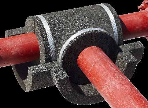
Overview

Prefabrication: tailor-made solutions								4

FOAMGLAS® prefabricated elements - general information						                                  5

Piping
PSH - Pipe half sections- single- & multi-layer configuration					                            6

PSQ - Pipe quarter sections - single- & multi-layer configuration 					                       7

PSG - Curved pipe segments - single- & multi-layer configuration 					                        8

Elbows - Bend insulation - single- & multi-layer configuration					                           9-10

T Pieces - T shaped intersections - single- & multi-layer configuration				                   11-12

Boxes - Flanges and valves - single- & multi-layer configuration					                         13-14

Pipe reducers - Conical & eccentric pipe reducers - single- & multi-layer configuration			    15

Pipe caps - End covers - single- & multi-layer configuration					                             16

TMH/TMP - Termination pieces for piping							                                                17

Victaulic elbows - Bend insulation, optimised for Victaulic fittings					                     18

Equipment
TSG - Curved tank wall segments - single- & multi-layer configuration				                     19

TSGP - Pre-assembled curved tank wall segments - single- & multi-layer configuration			       20

Vessel Head Segments - single- & multi-layer configuration					                               21

Vessel Head Segments - Pre-assembled, single- & multi-layer configuration				                 22

SHS - Spherical head segments - single- & multi-layer configuration					                      23

CSG - Segments for conical equipment - single- & multi-layer configuration				                24

CSGP - Pre-assembled elements for conical equipment - single- & multi-layer configuration		   25

Coatings - Pre-applied coatings								                                                       26-28

Example of our measurement sheet for FOAMGLAS® Boxes					                                     29

Information on types, dimensions and standardizations						                                   30-36

Selection of project references								                                                       37-39
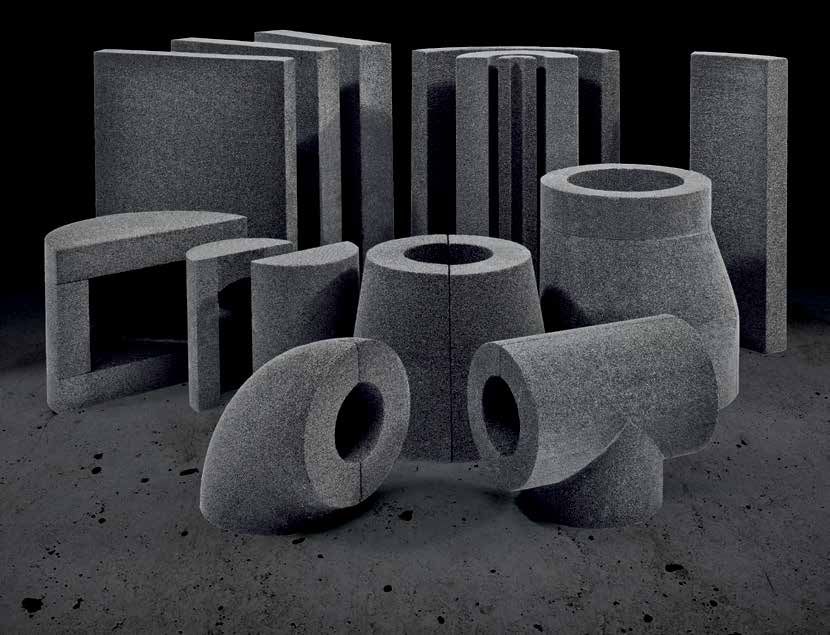
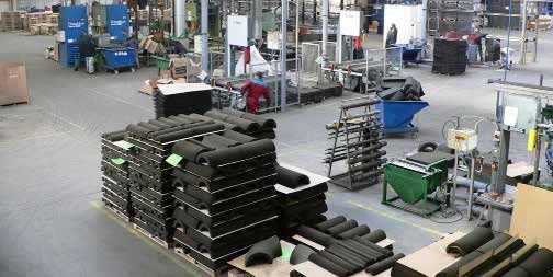
Prefabrication: tailor-made solutions
Tailor-made FOAMGLAS® insulation delivered on site for time- and cost-savings.

Due to the increasing demand for FOAMGLAS® insulation in custom-made elements, a special prefabrication plant
in Klasterec (Czech Republic) was established, where fabricated elements are produced in accordance with our high
quality standards.
Our FOAMGLAS® prefabricated elements are made out of FOAMGLAS® ONE™ insulation. The thermal properties are
in this case the same as FOAMGLAS® ONE™ slabs (for more information about the properties of FOAMGLAS® ONE™
insulation, we refer to the respective datasheet). On request, FOAMGLAS® prefabricated elements can also be manu-
factured from other grades.

Advantages of prefabrication                                       Available component pieces
√ Minimise the amount of on-site cutting - Every                   •   Straight pieces for pipework
FOAMGLAS® prefabricated element is delivered tailor-made           •   Elbows
for your specific project                                          •   T-pieces
                                                                   •   Reducers
√ Increase the speed of installation - Our prefabricated ele-      •   Termination pieces
ments can be installed straight out of the box.                    •   Valve fittings
                                                                   •   Flange fittings
√ Easy to fit - FOAMGLAS® prefabricated elements are easy to       •   Equipment pieces
install and manipulate with simple tools like a hand saw.          •   Heads
                                                                   •   Conical pieces
√ Removable for inspection - FOAMGLAS® prefabricated ele-
ments can be easily removed for maintenance purposes.

√ Easier handling of large sections of insulation -
FOAMGLAS® prefabricated elements are packed in easy to             Available factory-applied coatings:
handle quantities.                                                 •   HTAA: High temperature anti-abrasive
                                                                   •   LTAA: Low temperature anti-abrasive
√ Virtually every size and shape is possible - Our fabrication
                                                                   •   Bituminous cell filler for outer layer
facility is flexible enough to handle special requests and large
                                                                   •   PC® 700K: glass fiber mesh reinforced finish
units.
                                                                   •   TEROSTAT PC® FRi
√ Better installed quality - FOAMGLAS® machine-made, pre-          •   PITTWRAP® B100 alubutyl vapor barrier jacketing
fabricated elements are more consistent and higher in quality
compared to on-site manual cutted pieces.

                                                                                                                         4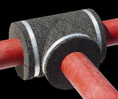
FOAMGLAS® prefabricated elements
General information

We provide tailor-made prefabricated insulation elements and in order to produce these to exact requirements,
we need accurate information to be able to produce them accordingly.

Service temperature
For every element we need to know the service temperature. Depending on the service temperature, we adapt our
manufacturing process to ensure the quality of every prefabricated element for the respective temperature range.

   o T ≤ ambient: we adhere our FOAMGLAS® prefabricated elements with hot bitumen.
   o T > ambient and ≤ 120°C: we adhere our FOAMGLAS® prefabricted elements with hot bitumen or
   					 high-temperature adhesive.
   o T > 120°C: we adhere our FOAMGLAS® prefabricated elements with high-temperature adhesive.
   o T < -175°C: we adhere our FOAMGLAS® prefabricated elements with high-temperature adhesive.

The additional data required is determined by the type of element throughout this document.

Anti-abrasive coating
Depending on the service conditions, an anti-abrasive coating can be applied to the inner surface of the
FOAMGLAS® prefabricated elements. The possible site application of an anti-abrasive on site must be indicated
with the order, since its application requires the internal diameter to be increased.

Dimensions
FOAMGLAS® prefabricated elements can be delivered in standard thicknesses of (25 – 30) – 40 – 50 – 60 – 70
– 80 – 90 – 100 and 120 mm. Other thicknesses are also available on request.

External coatings
Every FOAMGLAS® prefabricated element, regardless of type, can be delivered with a factory-applied external
coating. We have a large range of coatings, each with their individual properties and purpose. For more informa-
tion about their characteristics, please consult the respective product data sheets.

Traced piping
In case the inside insulation diameter is different from the pipe diameter, we manufacture in an oversize diameter
to make sure the FOAMGLAS® insulation layer fits perfectly. In this case the pipe diameter must also be indicated
in order that elbows may be formed to the correct radius.

ASTM regulations
All FOAMGLAS® prefabricated elements are produced to fully comply with ASTM C 1639 “Fabrication of Cellular
Glass Pipe and Tubing Insulation”.

Important The prefabricated and pre-assembled elements contained herein belong to our standard product
range. Other non-standard elements or special requests can be considered. Please consult us for more informa-
tion.

Additional information, product data sheets and safety data sheets are available online:
http://www.foamglas.com

                                                                                                              5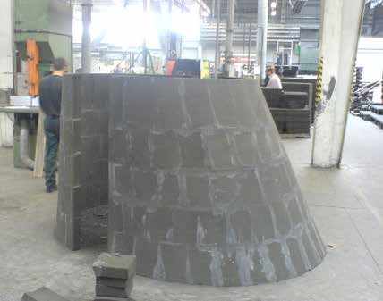
PSH
Pipe half sections for insulation of straight pipes

FOAMGLAS® insulation PSH is a prefabricated half section for the insulation of straight pipes in industrial and commerical pipe
work. The shells are supplied tailor-made, allowing for fast and easy installation.

FOAMGLAS® insulation pipe half sections are available in sizes up to and including nominal pipe diameters of 10" (273 mm).

Mandatory data                                                   Standard length (SL)
To be able to produce tailor-made prefabricated elements, we     Our half shells for pipe insulation are supplied in “Standard
need the following dimensions of the pipe to be insulated:       Lengths” of 600 mm. The length to be insulated is divided by
                                                                 0.6 and rounded up to the half standard length, i.e. one half shell
    Pipe diameter In mm, inch or DN.                             to be cut in two.
    Straight length                                              Example
    Insulation thickness and number of layers                    Required length: 80.5m
                                                                 Number of standard lengths: 80.5m : 0.6 m/SL = 134.16 SL.
    Service temperature
                                                                 When rounding to the half standard lenghts, we will obtain 134.5
                                                                 standard length.
                                                                 The furnished length will be: 134.5 SL x 0.6 m/SL = 80.7m.
Tolerances                                                       This is equal to 269 PSH’s.

The following tolerances applied to FOAMGLAS® insulation
PSH pieces ensure a normal free movement between the shells      Multi-layer configuration
and the pipes to be insulated:
                                                                 Same specification as single-layer configuration.
-      Inside shell diameter: +1 to +3 mm
-      Length: ± 2 mm                                            Tolerances on inside diameter: +2 to +4 mm
-      Thickness: ± 2 mm

                                                                                                                                6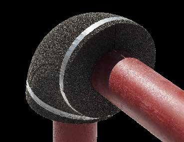
PSQ
Pre-assembled pipe quarter sections for insulation of straight pipes

FOAMGLAS® insulation PSQ is a prefabricated quarter section for the insulaton of straight pipes in industrial and commerical pipe
work. The shells are supplied tailor-made, allowing for fast and easy installation.

FOAMGLAS® insulation pipe quarter sections are available for nominal pipe sizes above 10" (273 mm) up to and including 24" (610
mm).

On request, half sections (PSH) can also be delivered within this range.

Advantages:
√ Number of segments to install is reduced by 50 - 75%

√ Similar reduction of joints and optional joint-filler

√ Optimised quality of the insulation (less field joints)

√ Best condition for pre-applied outside coating

Mandatory data                                                     Standard length (SL)
To be able to produce tailor-made prefabricated elements, we       Quarter shells for pipe insulation are supplied in “Standard
need the following dimensions of the pipe to be insulated:         Lengths” of 600 mm. The length to be insulated is divided by 0.6
                                                                   to determine the number of Standard Lengths. This calculated
                                                                   number will be rounded up to the next half length.
    Pipe diameter In mm, inch or DN.
    Straight length                                                Example
    Insulation thickness and number of layers                      Required length: 80.5m
                                                                   Number of standard lengths: 80.5m : 0.6 m/SL = 134.16 SL.
    Service temperature                                            When rounding to the half standard lenghts, we will obtain 134.5
                                                                   standard length.
                                                                   The furnished length will be: 134.5 SL x 0.6 m/SL = 80.7m. This
                                                                   is equal to 538 PSQ’s.
Tolerances
The following tolerances applied to FOAMGLAS® PSQ ensure a         Multi-layer configuration
normal free movement between the shells and the pipes to be
insulated:                                                         Same specification as single-layer configuration.

-      Inside shell diameter: +1 to +3 mm                          Tolerances on inside diameter: +2 to +4 mm
-      Length: ± 2 mm
-      Thickness: ± 2 mm

                                                                                                                               7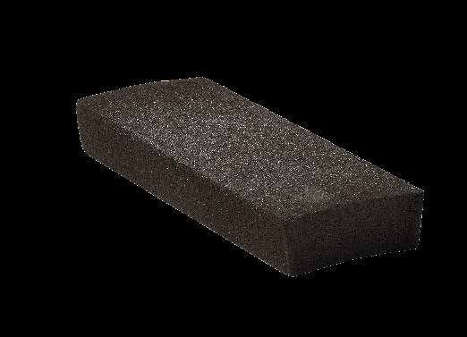
PSG
Curved segments for insulation of straight pipes

FOAMGLAS® insulation PSG is a prefabricated segment for the insulation of straight pipes in industrial and commerical pipe work.
The segments are supplied tailor-made, allowing for fast and easy installation.
FOAMGLAS® insulation egments are available in sizes for nominal pipe diameters above 24" (610 mm). Segmented pipe insulation
will be fabricated in equal widths in a way that the pipe circumference is covered without additional field cuts.
On request, quarter sections (PSQ) can also be delivered within this range.

Mandatory data                                                     Standard length (SL)
To be able to produce tailor-made prefabricated elements, we       FOAMGLAS® PSG prefabricated segments have a standard
need the following dimensions of the pipe to be insulated:         length of 600 mm. The length of the pipe to be insulated will be
                                                                   divided by 0.6 to determine the number of Standard Lengths.
    Pipe diameter In mm, inch or DN.                               This calculated number will be rounded up to the next half
                                                                   length.
    Straight length
    Insulation thickness and number of layers                      Number of segments per circumference
    Service temperature                                            All FOAMGLAS® PSG prefabricated segments have an exterior
                                                                   width of maximum 225 mm and are supplied in equal widths.
                                                                   This determines the number of segments per SL.

Tolerances
                                                                   Multi-layer configuration
The following tolerances applied to FOAMGLAS® PSG ensure a
normal free movement between the segments and the pipelines        Same specification as single-layer configuration.
to be insulated:
                                                                   Tolerances on inside diameter: +2 to +4 mm
-      Inside diameter: +1 to +3 mm
-      Length: ± 2 mm
-      Thickness: ± 2 mm
-      Width: ± 2 mm

                                                                                                                               8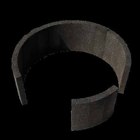
Elbows
Bend insulation

FOAMGLAS® insulation elbows are prefabricated fittings for the insulation of elbows in industrial and commerical pipe work. The
elbows are supplied tailor-made, allowing for fast and easy installation.

FOAMGLAS® insulation elbows are available in sizes for diameters up to and including 914 mm. FOAMGLAS® prefabricated
elbows have a standard radius of curvature of R = 1.5 D (type 3D) and can be supplied in the same thicknesses as sections and
segments for straight pipes.

Mandatory data                                                     Additional info (also see appendix 1.2)
To be able to produce tailor-made prefabricated elements, we       1 Our standard radius of curvature is equal to one and a half
need the following dimensions of the elbow to be insulated:        diameter (1.5D). These elbows are also referred to as long
                                                                   radius or type 3D. (The rule R = 1.5D applies to the nominal
    Pipe diameter In mm, inch or DN.                               diameter in inches).

    Service temperature                                            2 D is not the real diameter, but the nominal inch size. To
    Insulation thickness                                           convert to mm, nominal inch size should be multiplied by
                                                                   25.4. Exception is made for small bore piping (< 1”): they
    Desired angle                                                  usually have the same radius as a 1” elbow.
    Radius (or elbow type)
                                                                   Example 1: pipe diameter = 60.3 mm, elbow 1.5D --> radius =
                                                                   2 x 25.4 x 1.5 = 76.2 mm
Tolerances                                                         Example 2: pipe diameter = 3/4", elbow 1.5D --> radius = 1 x
The following tolerances applied to FOAMGLAS® prefabricated        25.4 x 1.5 = 38.10 mm.
elbows ensure a normal free movement between the elbows
and the piping to be insulated:
                                                                   3 Elbows can be cut to a different radius of curvature.

-      Inside diameter :
                                                                   4 In case the inside insulation diameter is different
                                                                   from the pipe diameter (e.g. traced pipe work or overfit
           o    < 273 mm : +1 to +3 mm                             insulation), both have to be submitted. We have to fabricate
           o    ≥ 273 mm : +1 to +5 mm                             an oversize diameter, but the radius will be calculated as
           o    ≥ 500 mm : +2 to +8 mm                             the following: nominal pipe size (inch) x 25.4 mm x 1.5.

-      Curvature radius :
           o    < 273 mm : ± 3 mm
           o    ≥ 273 mm : ± 5 mm
           o    ≥ 500 mm : ± 10 mm
-      Insulation thickness : ± 2 mm

                                                                                                                             9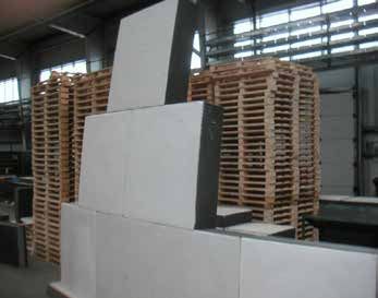
Elbows
Bend insulation, multi layer configuration

FOAMGLAS® insulation elbows are prefabricated fittings for the insulation of elbows in industrial and commerical pipe work. The
elbows are supplied tailor-made, allowing for fast and easy installation.

FOAMGLAS® insulation elbows are available in sizes for diameters up to and including 914 mm. FOAMGLAS® prefabricated elbows
have a standard radius of curvature of R = 1.5 D (type 3D) and can be supplied in the same thicknesses as sections and segments
for straight pipes.

Mandatory data                                                   Specific for multi-layer elbows:
To be able to produce tailor-made prefabricated elements, we     • Second layer is fabricated with 90° staggered longitudinal
                                                                    joint.
need the following dimensions of the elbow to be insulated:
                                                                 • Second layer will extend 75 mm at both ends. As such,
    Pipe diameter In mm, inch or DN.                                staggering of circumferential joints is guaranteed.
    Service temperature
    Insulation thickness
    Desired angle
                                                                  Additional info (also see appendix 1.2)
    Radius (or elbow type)                                        1 Our standard radius of curvature is equal to one and a half
                                                                  diameter (1.5D). These elbows are also referred to as long
                                                                  radius or type 3D. (The rule R = 1.5D applies to the nominal
Tolerances                                                        diameter in inches).
The following tolerances applied to FOAMGLAS® prefabricated
elbows ensure a normal free movement between the elbows           2 D is not the real diameter, but the nominal inch size. To
and the piping to be insulated:                                   convert to mm, nominal inch size should be multiplied by
                                                                  25.4. Exception is made for small bore piping (< 1”): they
-      Inside diameter :                                          usually have the same radius as a 1” elbow.
           o    < 273 mm : +2 to +4 mm
           o    ≥ 273 mm : +3 to +5 mm                            Example 1: pipe diameter = 60.3 mm, elbow 1.5D --> radius =
           o    ≥ 500 mm : +6 to +12 mm                           2 x 25.4 x 1.5 = 76.2 mm

-      Curvature radius :                                         Example 2: pipe diameter = 3/4", elbow 1.5D --> radius = 1 x
            o < 273 mm : ± 3 mm                                   25.4 x 1.5 = 38.10 mm.
            o ≥ 273 mm : ± 5 mm                                   3 Elbows can be cut to a different radius of curvature.
            o ≥ 500 mm : ± 10 mm
-      Insulation thickness : ± 2 mm                              4 In case the inside insulation diameter is different from
                                                                  the pipe diameter (e.g. traced pipe work or overfit insulation),
                                                                  both have to be submitted. We have to fabricate an oversize
                                                                  diameter, but the radius will be calculated as the following:
                                                                  nominal pipe size (inch) x 25.4 x 1.5.

                                                                                                                              10
T-Pieces
T-shaped insulation
FOAMGLAS® insulation T-pieces are designed to easily insulate intersections in industrial and commerical pipe work. The T-pieces
are supplied tailor-made, allowing for fast and easy installation.
FOAMGLAS® insulation can be prefabricated in equal, as well as unequal T-pieces (of which Ø1 ≠ Ø2).
Mandatory data Additional info
To be able to produce tailor-made prefabricated elements, we 1 Our prefabricated T pieces are delivered with an inner
need the following dimensions of the T piece to be insulated: corner fitting a welded Tee (see fabrication design in the
middle of this page). In case of fabricated (radiused) T pieces,
Pipe diameter 1 In mm, inch or DN. it may be necessary to abrade the inner side to make them fit
completely.
Pipe diameter 2 In mm, inch or DN.
Insulation thickness 2 We don’t fabricate T pieces for angles other than 90°.
Service temperature
Alternative: We can also provide T Boxes for the insulation
of pipe work intersections. See respective sheet for full
Tolerances details.
The following tolerances applied to FOAMGLAS® prefabricated
T pieces ensure a normal free movement between the T pieces
and the piping to be insulated:
- Inside shell diameter: +1 to +3 mm
- Length: ± 2 mm
- Thickness: ± 2 mm
11T-pieces
T-shaped insulation, Multi-layer configuration
FOAMGLAS® insulation T-pieces are designed to easily insulate intersections in industrial and commerical pipe work. The T-pieces
are supplied tailor-made, allowing for fast and easy installation.
FOAMGLAS® insulation can be prefabricated in equal, as well as unequal T-pieces (of which Ø1 ≠ Ø2).
Mandatory data Additional info
To be able to produce tailor-made prefabricated elements, we 1 Our prefabricated T pieces are delivered with an inner
need the following dimensions of the T piece to be insulated:
corner fitting a welded Tee (see fabrication design in the
middle of this page). In case of fabricated (radiused) T pieces,
Pipe diameter 1 In mm, inch or DN. it may be necessary to abrade the inner side to make them fit
Pipe diameter 2 In mm, inch or DN. completely.
Insulation thickness and number of layers 2 We don’t fabricate T pieces for angles other than 90°.
Service temperature
Alternative: We can also provide multi-layer T Boxes for
the insulation of pipe work intersections. See respective
Tolerances sheet for full details.
The following tolerances applied to FOAMGLAS® prefabricated
T pieces ensure a normal free movement between the T pieces
and the piping to be insulated: Specific for multi-layer T pieces:
- Inside shell diameter: +2 to +4 mm • Second layer is fabricated with 90° staggered longitudinal
joint.
- Length: ± 2 mm
• Second layer will extend 75 mm at both ends. As such,
- Thickness: ± 2 mm staggering of circumferential joints is guaranteed.
• The first layer is supplied in 3 pieces, the supplementary
layers in two pieces.
• Depending on the size, the number of pieces can be
variable
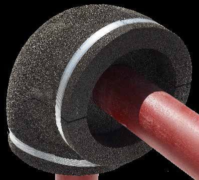
12Boxes
Flange and valve insulation
FOAMGLAS® insulation prefabricated boxes are designed to insulate valves and flanges in ndustrial and commerical pipe work. The
boxes are supplied tailor-made, allowing for fast and easy installation.
FOAMGLAS® insulation can be prefabricated in boxes for practically all dimensions. The only limitation is the ability to transport
and handle it safely at the job site. If a fabricated box turns out to be too large to transport in one piece, it can be delivered in multiple
sections and reassembling can be performed on site.
Tolerances
The following tolerances applied to FOAMGLAS® prefabricated boxes ensure a normal free movement between the boxes and the
equipment to be insulated:
- Inside shell diameter : +1 to +5 mm
- Thickness : ± 2 mm
- Width + Length + Height : < 273 mm: -1 to +5 mm
≥ 273 mm: -1 to +9 mm
Every single box is tailor-made to the requirements of the customer. This means the customer should provide certain details
(see our measurement sheet on page 29 for more information).
We have three standardized boxes in our product range:
See appendix 1.4 and 1.5 for information on types, dimensions and standardizations
1 F box: F-Type Box: flange cover.
2 V Box: V-Type Box: valve cover.
3 T box: T-Type Box: Valve cover with
extended insulation of the valve
stem.
13Boxes
Flange and valve insulation, multi-layer configuration
FOAMGLAS® insulation prefabricated boxes are designed to insulate valves and flanges in ndustrial and commerical pipe work. The
boxes are supplied tailor-made, allowing for fast and easy installation.
FOAMGLAS® insulation can be prefabricated in boxes for practically all dimensions. The only limitation is the ability to transport
and handle it safely at the job site. If a fabricated box turns out to be too large to transport in one piece, it can be delivered in multiple
sections and reassembling can be performed on site.
We have three standardized multi layer boxes in our product range:
See appendix 1.4 and 1.5 for information on types, dimensions and standardizations
1 Double-layer F box: F-Type Box:
flange cover.
2 Double-layer V Box: V-Type Box: valve
cover.
3 Double-layer T box: T-Type Box: Valve
cover with extended insulation of the
valve stem.
14Pipe reducers
Insulation for pipe reducers
FOAMGLAS® insulation pipe reducers are designed to easily insulate pipes of which the diameter changes in industrial and
commerical pipe work. The pipe reducers are supplied tailor-made, allowing for fast and easy installation. By using prefabricated
pipe reducers, the amount of on-site cutting and fitting is reduced to a minimum as cutting sections/segments is no longer
necessary.
Mandatory data Additional info
To be able to produce tailor-made prefabricated elements, 1. At both sides of the reducer, a length of straight pipe
we need the following dimensions of the pipe reducer to be insulation will be included. This insulation piece will extend 50
insulated: mm either side of both fitting welds
2. For the dimensioning of the reducer itself, the applicable
Pipe diameter 1 In mm, inch or DN. ANSI standards will apply.
Pipe diameter 2 In mm, inch or DN.
see appendix 1.3 for standardized dimensions
Insulation thickness
Service temperature
Concentric or eccentric type Specific for multi-layer pipe reducers:
• Second layer is fabricated with staggered longitudinal joint.
Tolerances • Second layer will extend 75 mm at both ends. As such,
The following tolerances applied to FOAMGLAS® prefabricated staggering of circumferential joints is guaranteed.
pipe reducers ensure a normal free movement between the
pipe reducers and the piping to be insulated:
- Inside shell diameter: +1 to +3 mm
- Length: ± 2 mm
- Thickness: ± 2 mm Eccentric pipe reducer
concentric pipe reducer
15Pipe end caps
Insulation for pipe end caps
FOAMGLAS® insulation pipe end caps are designed to easily insulate the end points of in industrial and commerical pipe work.
The pipe end caps are supplied tailor-made, allowing for fast and easy installation. By using prefabricated pipe end caps, the
amount of on-site cutting and fitting is reduced to a minimum.
Mandatory data Additional info
To be able to produce tailor-made prefabricated elements, 1. Prefabricated end cap insulation will have flat ends. This
we need the following dimensions of the pipe end cap to be reduces fabrication costs and simplifies multiple layer
insulated: systems.
2. For the dimensioning of the end cap itself, the applicable
Pipe diameter In mm, inch or DN. ANSI standards will apply.
Insulation thickness and number of layers
3. The total length of the end cap will be:
Service temperature
Diameters ≤ 10" : 300 mm
Diameters > 10" : 600 mm
Tolerances
Specific for multi-layer end caps:
The following tolerances applied to FOAMGLAS®
prefabricated pipe end caps ensure a normal free • Second layer is fabricated with staggered longitudinal
movement between the end caps and the object to be joint.
insulated.
• Circumferential joints will be staggered as per typical
- Inside shell diameter: +1 to +3 mm drawing.
- Length: ± 2 mm
• Tolerances on inside diameter of 2nd layer: +2 to +4
- Thickness: ± 2 mm
mm
Single-layer end cap Double-layer end cap
16Victaulic elbows
Bend insulation, optimised for Victaulic fittings
FOAMGLAS® insulation victaulic elbows are prefabricated fittings designed for the insulation of elbows in industrial and commerical
pipe work that are equiped with mechanical pipe joining systems. The elbows are supplied tailor-made, allowing for fast and easy
installation.
FOAMGLAS® insulation elbows are available in sizes for diameters up to and including 914 mm. FOAMGLAS® prefabricated elbows
have a standard radius of curvature of R = 1.5 D (type 3D) and can be supplied in the same thicknesses as sections and segments
for straight pipes.
Mandatory data Additional info
To be able to produce tailor-made prefabricated elements, we In order to provide a clear overview, we have standardized
need the following dimensions of the bend to be insulated: prefabricated Victaulic elbows. See table below for all
possibilities.
Pipe diameter In mm, inch or DN.
Angle and radius
FOAMGLAS®
Coupling dimensions or type DN Diameter mm
Thickness mm
Insulation thickness 50 60 25
Service temperature
65 76 25
80 89 25
Tolerances 100 114 25
The following tolerances applied to FOAMGLAS® prefabricated 125 140 30
Victaulic elbows ensure a normal free movement between the
elbows and the piping to be insulated: 150 168 30
- Inside diameter : 200 219 40
o < 273 mm : +1 to +3 mm
o ≥ 273 mm : +1 to +5 mm Multi-layer configuration
o ≥ 500 mm : +2 to +8 mm
Additional layers of FOAMGLAS® insulation will be normal
FOAMGLAS® elbows as described in the respective sheet for
- Curvature radius : this element.
o < 273 mm : ± 3 mm
o ≥ 273 mm : ± 5 mm
o ≥ 500 mm : ± 10 mm
- Insulation thickness : ± 2 mm
18TSG
Curved segments for vessels and tanks
FOAMGLAS® insulation TSG is a prefabricated segment designed for the insulation of large diameter pipes and cylindrical tank
walls. The segments are supplied tailor-made allowing for fast installation and are suitable for insulating all kind of tank wall
surfaces.
FOAMGLAS® insulation TSG segments are available in sizes for diameters above 914 mm.
Mandatory data
To be able to produce tailor-made prefabricated elements, we
need following dimensions of the tank to be insulated:
Exterior tank diameter
Insulation thickness and number of layers
Length of cylindrical part to be insulated
Service temperature
Tolerances
The following tolerances applied to FOAMGLAS® TSG ensure
a normal free movement between the segments and the
equipment to be insulated:
- Inside diameter: +1 to +3 mm
- Length: ± 2 mm
- Width: ± 2 mm
- Thickness: ± 2 mm
Additional info
Size of delivered segments:
For diameters up to 1999 mm segments of 600 mm long
and approximately 220 mm wide
For diameters 2000 mm and above segments of 600 mm
long and approximately 445 mm wide
19TSGP
Pre-assembled curved segments for vessels and tanks
FOAMGLAS® insulation TSGP are preassembled TSG segments designed for the insulation of large diameter pipes and cylindrical
tank walls. Multiple FOAMGLAS® TSG segments, whether being single- or multi-layered, can be preassembled in our production
unit to create large sections for the insulation of equipment and tank walls. This is possible for practically all dimensions, the only
limitations are transport and the ability to handle it safely on the job site.
Using preassembled TSGP segments reduces the amount of on-site fitting and glueing which results in faster installation times.
Multi-layer configuration
Additional layers can be adhered on top of each other in a cross pattern. As such, staggering of all joints is guaranteed.
Advantages:
√ Number of segments to install is reduced by 50 - 75%
√ Similar reduction of joints and optional joint-filler
√ Optimised quality of the insulation (less field joints)
√ Best condition for pre-applied outside coating
20Vessel heads
Vessel head segments
FOAMGLAS® vessel head segments are prefabricated segments designed for the insulation of vessel heads. The segments are
supplied tailor-made allowing for fast installation and can be fabricated to fit all of the common types of vessel heads.
FOAMGLAS® insulation can be prefabricated in vessel head segments for diameters from 750 mm up to 5000 mm and even larger..
Mandatory data
To be able to produce tailor-made prefabricated elements, we need the following dimensions of the tank head to be insulated:
Outer shell diameter = Do
Large radius = R
Small radius = r
H+h
Thickness of vessel head = s
H: Head height from tangent line
h: Distance between tangent line and weld line
Thus, we produce a prefabricated head based on following figures:
The large radius, being R + s
The small radius, being r + s
Example: HEH-type head with Do of 1000 mm and head thickness of 20 mm. FOAMGLAS® insulation thickness of 60 mm.
Delivered prefabricated head will be as following: diameter = 1000 | R = 1020 | r = 120 | d = 60
See appendix 1.1 for more information
Tolerances Additional info
The following tolerances applied to FOAMGLAS® vessel head A tailor made FOAMGLAS® vessel head consists of different
segments ensure a normal free movement between shells and types of segments.
the vessel head to be insulated:
- Curvature: ± 5 mm It is possible to choose our pre-assembled heads (see following
page for more information). If not, you will obtain tailor-made
- Length: ± 2 mm
separate segments which need to be installed.
- Width: ± 2 mm
- Thickness: ± 2 mm
21Vessel heads
Preassembled vessel head
Multiple FOAMGLAS® vessel head segments, regardless of being single or multi-layered, can be adhered in our production unit to
create a completely preassembled vessel head.
Advantages: Multi-layer configuration
Minimise the amount of on-site cutting The second layer of FOAMGLAS® prefabricated head insulation
Every FOAMGLAS® prefabricated element is delivered tailor- cannot be of the same type as the first layer. E.g.: HEH first layer
made for your project which has a positive effect on the labour + HEH second layer will never fit.
cost.
The solution is to mention the head type and give complete
Increase the speed of installation data for the first layer. We will calculate the correct radiuses
Directly fit the FOAMGLAS® prefabricated elements around he based on these figures and our experience.
tank. This decreases the installation times making shutdowns
more effective and cost-efficient. Example: HEH-type head with OD of 1000 mm and head thick-
ness of 20 mm. FOAMGLAS® insulation thickness of 60 mm
Easily removable for inspection (first layer) + 50 mm (second layer).
FOAMGLAS® prefabricated elements can easily removed and
reinstalled for maintenance purposes. The second layer will have: diameter = 1120 | R = 1080 | r = 180
| d = 50
Easier handling of large sections of insulation
FOAMGLAS® prefabricated elements are packed in easy to See appendix 1.1 for more information
handle quantities.
Better installed quality
FOAMGLAS® prefabricated elements are machine made and
have a constant quality across the range.
Pre-assembling of vessel heads is possible for practically all
dimensions. The only limitations are transport and the ability
to handle it safely on the job site. If a prefabricated vessel head
turns out to be too large to transport in one piece, we will deliver
it in multiple sections and reassembling has to be done on site .
22SHS
Spherical head segments
FOAMGLAS® insulation SHS segments are prefabricated spherical head segment designed for the insulation of spheres and other
spherical shaped equipment. The segments are supplied tailor-made allowing for fast installation and are suitable for insulating all
kind of spherical tanks and industrial equipment.
FOAMGLAS® insulation can be prefabricated in spherical head segments for diameters from 950 mm up to 20 000 mm. There are
two types of types of SHS, depending on the diameter:
• Segments of 295 x 295 mm for diameters smaller than 1800 mm
• Segments of 295 x 445 mm for diameters of 1800 mm and up
Mandatory data Multi-layer configuration
To be able to produce tailor-made prefabricated elements, Same specification as single-layer configuration.
we need the following dimensions of the sphere to be insu-
lated:
Exterior object radius
Insulation thickness and number of layers
Service temperature
Tolerances
The following tolerances applied to FOAMGLAS® SHS ensure a
normal free movement between the segments and the equip-
ment to be insulated:
- Curvature: ± 5 mm
- Length: ± 2 mm
- Width: ± 2 mm
- Thickness: ± 2 mm
23CSG
Segments for conical equipment
FOAMGLAS® insulation CSG segments are prefabricated segments designed for the insulation of conical vessel ends or conical
transition parts. The segments are supplied tailor-made allowing for fast installation and are suitable for insulating all kind of
conical industrial equipment.
FOAMGLAS® insulation can be prefabricated in radiused conical segments for diameters from 450 mm up to 4000 mm (CSGR) and
in flat conical segments for diameters above 4000 mm (CSGF).
• CSGR (radiused): Diameters < 4000mm
• CSGF (flat): Diameters ≥ 4000mm
Mandatory data Tolerances
To be able to produce tailor-made prefabricated elements, we The following tolerances applied to FOAMGLAS® CSG ensure a
need following dimensions of the tank to be insulated: normal free movement between segments and the equipment
to be insulated:
Large diameter - Inside diameter: +1 to +3 mm
Small diameter - Length: ± 2 mm
Angle(s) if not concentric - Width: ± 2 mm
Straight height or length - Thickness: ± 2 mm
Insulation thickness and number of layers
Service temperature Additional info
1. The length of the conical segments is 450 mm.
CSGF CSGR 2. The width is variable with a maximum of 295 mm. It is
calculated in order to allow a ringwise application of the
segments without additional adjusting.
Multi-layer configuration
Same specification as single-layer configuration.
24CSGP
Pre-assembled elements for conical equipment
FOAMGLAS® insulation preassembled trapezoidal parts are designed for the insulation of trapezoidal shaped equipment in indus-
trial pipework. The conical elements are supplied tailor-made, allowing for fast and easy installation.
FOAMGLAS® insulation can be prefabricated in trapezoidal parts for practically all dimensions. The only limitation is the ability to
transport and handle it safely to the job site. If a preassembled trapezoidal part turns out to be too large to transport in one piece,
it can be delivered in multiple sections and reassembling has to be done on-site.
Mandatory data Multi layer configuration
To be able to produce tailor-made prefabricated elements, we Same specification as single-layer configuration.
need the following dimensions of the pipe reducer to be insu-
lated:
Large diameter
Small diameter
Angle(s) if not concentric
Straight height or length
Insulation thickness and number of layers
Service temperature
Tolerances
The following tolerances applied to FOAMGLAS® preassembled
trapezoidal parts ensure a normal free movement between the
parts and the equipment to be insulated:
- Inside diameter: +1 to +5 mm
- Length: ± 2 mm
- Thickness: ± 2 mm
25Coatings
Pre-applied coatings
Why pre-applied coatings?
Through years of experience with our accessory products, we have the necessary know-how to apply these at our production
units. This experience enables us to produce pre-applied FOAMGLAS® insulation in the most optimized circumstances.
Advantages
• Simpler pre-coated systems
• Less accessory materials on site
• Prefabrication = quicker installation
• Wide temperature range
• CUI prevention
Inside coatings
Anti abrasive coating
The anti abrasive coating is applied to the inside of the FOAMGLAS® prefabricated ele-
ment. It reduces abrasion from vibrating piping or equipment. It has strong adhesive
qualities through a wide temperature range.
Both a Low Temperature Anti Abrasive (LTAA) and a High Temperature Anti Abrasive
(HTAA) is available. Depending on the service temperature, either of these is used:
LTAA: temperature range of -180°C to +130 °C
HTAA: temperature range of -268°C to +430°C
PC® 700K
PC® 700K is a combination of a two-component inorganic mortar and a glass cloth
reinforcement to protect the FOAMGLAS® insulation system to suffer from thermal
cracking.
It is ideal when the temperatures are very low, very high, or when they cycle rapidly.
Temperature range: -196°C to +400°C
26Coatings
Pre-applied coatings
Outside coatings
Terostat PC® FRi
Terostat PC® FRi is a vapor/ weather barrier coating and sealant/adhesive especially
formulated for use with FOAMGLAS® insulation in the low to moderate temperature
range.
Field application consists of sealing the section joints with the same TEROSTAT PC®
FRi which acts as a highly flexible sealant and adhesive. TEROSTAT PC® FRi provides
a clean look and a flexible but strong protection.
Temperature range: -50°C to +120°C
Advantages:
• Joint-free, continuous coating
• Strong & flexible coating/adhesive
• Wide temperature range
• CUI preventive system
• Solvent free
• Reduced installation time
Bituminous cell filler
The Bituminous cell filler is specially formulated for use with FOAMGLAS® insulation
in the low to moderate temperature range. It ‘fills’ the open cells on the surface to
protect the unique cell structure of FOAMGLAS® insulation.
PITTWRAP® B100 foil
This Alubutyl foil is a versatile foil with outstanding vapour barrier and weatherproof
properties. It is strengthened by PET foil to withstand cracks and leaks.
27Measurement sheet - FOAMGLAS® Boxes
ALL DIMENSIONS ARE OUTSIDE BOX !
V-Type BOX
L (mm) W (mm) CLIENT:
ORDER :
h (mm)
ITEM NR:
H (mm)
BOX TYPE V or F or T
END COVERS YES if complete
NO if none
or give number (pcs)
INSULATION THICKNESS (mm)
+ mm
F-Type BOX Temperature ≤+120°C operating temperature
DIMENSIONS (mm) Outside outer BOX !
L
W
W (mm) H >V-Box only
h >V-Box (optional)
S >T-Box only
l >T-Box (optional)
W1 >T-Box, only if ≠ W
Dimensions in capital letters are obligatory,
small letters only if applicable.
T-Type BOX
W1 (mm) QUANTITY pieces
S (mm)
PRE-APPLIED COATINGS ▪ LTAA
I (mm) ▪ HTAA
Inside Box ▪ BIT. CF
▪ ASJ FOIL
▪ PC® 700K
W (mm) Outside Box ▪ PITTWRAP® B100
▪ TEROSTAT PC® FRi
L (mm)
Page:
29Appendix - Information on types,
dimensions and standardizations
INFORMATION ON TYPES, DIMENSIONS, STANDARDIZATIONS
1.1 Vessel heads
VESSEL HEADS
Designation ENG Torispherical head Ellipsoidal head
DE Klöpperboden Korbbogenboden
FR Fond GRC Fond KBB
PCE HEH HKH
Fabrication standards DE DIN 28011 DIN 28013
FR NFE 81-102
INT
Large radius R= Do 0.8 x Do
Small radius r= 0.1 x Do 0.154 x Do
Designation ENG Elliptical head 1.9:1 Elliptical head 2:1
DE Elliptischer Boden 1.9:1 Elliptischer Boden 2:1
FR Fond elliptique 1.9:1 Fond elliptique 2:1
Fabrication standards DE
FR NFE 81-103
INT ASME VIII Div.1
Large radius R= 0.8621 x Di 0.9045 x Di
Small radius r= 0.1855 x Di 0.1727 x Di
Designation ENG Spherical head; boiler end Dished head; tank end
DE Flachgewölbter Boden Gewölbter Tankboden
FR Fond PRC Fond MRC
Fabrication standards DE DIN 6608/6616
FR NFE 81-101 NFE 81-104
INT EN 12285-1
Large radius R= 1.0 - 1.5 x Do Do
Small radius r= 30mm - 50mm Do/30
Designation ENG Curved disc Hemispherical head
DE Gewölbte Scheibe Halbsphärischen Boden
FR Calotte sphérique Fond hemisphérique
Fabrication standards DE
FR
INT
Large radius R= 0.8 - 1.5 x Do 0.5 x Do
Small radius r= 0 0
30Appendix - Information on types,
dimensions and standardizations
1.1 Vessel heads
Notes (Not valid for the hemispherical head type)
1. The details above are tankbuilders' information.
These R- and r-values are defined as inside radiuses.
For our fabrication we have to add the steel thickness
R fab = R + s
R fab = r + s
2. The second layer in a double-layer system can never be one of the types above.
Specify simply as second layer and it will be fabricated as fitting upon the first layer or calculate Do and radiuses
starting from the first layer.
Thanks to decades of experience and specialised calculation programmes, we are able to produce fitted FOAMGLAS®
insulation for every type of vessel head, regardless being standardized or custom, typical or combined.
FOAMGLAS® prefabricated elements that we deliver can be:
s s Do
Do
Eliptical heads: SHS segments + SRS segments
s Do s Do
flat heads: SRS segments + FOAMGLAS slabs ®
Conical heads: SRS + CSG segments
s
Do s
Do
Dished heads: SHS segments Hemispherical heads: SHS segments
31Appendix - Information on types,
dimensions and standardizations
1.2 Elbows
Elbow radiuses according to ANSI B16.9
Elbow radiuses according to ANSI B 16.9
ANSI B16.9 ANSI B16.28
Diameter Long radius Short radius
DN inch mm R= 1,5 D R= 1,0 D
15 0,5 21 38
20 0,75 27 38
25 1 34 38 25
32 1,25 42 48 32
40 1,5 48 57 38
50 2 60 76 51
65 2,5 76 95 64
80 3 89 114 76
3,5 102 133 89
100 4 114 152 102
127 172 114
125 5 140 191 127
150 6 168 229 152
200 8 219 305 203
250 10 273 381 254
300 12 324 457 305
350 14 356 533 356
400 16 406 610 406
450 18 457 686 457
500 20 508 762 508
550 22 559 838 559
600 24 610 914 610
650 26 660 991
700 28 711 1067
750 30 762 1143
800 32 813 1219
900 36 914 1372
32Appendix - Information on types,
dimensions and standardizations
1.3 Reducers
Concentric and eccentric reducers according to ANSI B16.9
DN Inch mm Length (mm) DN Inch mm Length (mm)
20 x 15 0,75 x 0,5 27 x 21 100 x 90 4 x 3,5 114 x 102
38
20 x 10 0,75 x 3/8 27 x 17 100 x 80 4x3 114 x 89
25 x 20 1 x 0,75 34 x 27 100 x 65 4 x 2,5 114 x 76 102
51
25 x 15 1 x 0,5 34 x 21 100 x 50 4x2 114 x 60
32 x 25 1,25 x 1 42 x 34 100 x 40 4 x 1,5 114 x 48
32 x 20 1,25 x 0,75 42 x 27 51 125 x 100 5x4 140 x 114
32 x 15 1,25 x 0,5 42 x 21 125 x 90 5 x 3,5 140 x 102
40 x 32 1,5 x 1,25 48 x 42 125 x 80 5x3 140 x 89 127
40 x 25 1,5 x 1 48 x 34 125 x 65 5 x 2,5 140 x 76
64
40 x 20 1,5 x 0,75 48 x 27 125 x 50 5x2 140 x 76
40 x 15 1,5 x 0,5 48 x 21 150 x 125 6x5 168 x 140
50 x 40 2 x 1,5 60 x 48 150 x 100 6x4 168 x 114
50 x 32 2 x 1,25 60 x 42 150 x 90 6 x 3,5 168 x 102 140
76
50 x 25 2x1 60 x 34 150 x 80 6x3 168 x 89
50 x 20 2 x 0,75 60 x 27 150 x 65 6 x 2,5 168 x 76
65 x 50 2,5 x 2 76 x 60 200 x 150 8x6 219 x 168
65 x 40 2,5 x 1,5 76 x 48 200 x 125 8x5 219 x 140
89 152
65 x 32 2,5 x 1,25 76 x 42 200 x 100 8x4 219 x 114
65 x 25 2,5 x 1 76 x 34 200 x 90 8 x 3,5 219 x 102
80 x 65 3 x 2,5 89 x 76 250 x 200 10 x 8 273 x 219
80 x 50 3x2 89 x 60 250 x 150 10 x 6 273 x 168
89 178
80 x 40 3 x 1,5 89 x 48 250 x 125 10 x 5 273 x 140
80 x 32 3 x 1,25 89 x 42 250 x 100 10 x 4 273 x 114
90 x 80 3,5 x 3 102 x 89
90 x 65 3,5 x 2,5 102 x 76
90 x 50 3,5 x 2 102 x 60 102
90 x 40 3,5 x 1,5 102 x 48
90 x 32 3,5 x 1,25 102 x 42
31Appendix - Information on types,
dimensions and standardizations
1.3 Reducers
Concentric and eccentric reducers according to ANSI B16.9
DN Inch mm Length (mm) DN Inch mm Length (mm)
300 x 250 12 x 10 324 x 273 650 x 600 26 x 24 660 x 610
300 x 200 12 x 8 324 x 219 650 x 500 26 x 22 660 x 559
203 610
300 x 150 12 x 6 324 x 168 650 x 450 26 x 20 660 x 508
300 x 125 12 x 5 324 x 140 650 x 400 26 x 18 660 x 457
350 x 300 14 x 12 356 x 324 700 x 650 28 x 26 711 x 660
350 x 250 14 x 10 356 x 273 700 x 600 28 x 24 711 x 610
330 610
350 x 200 14 x 8 356 x 219 700 x 550 28 x 22 711 x 559
350 x 150 14 x 6 356 x 168 700 x 500 28 x 20 711 x 508
400 x 350 16 x 14 406 x 356 750 x 700 30 x 28 762 x 711
400 x 300 16 x 12 406 x 324 750 x 650 30 x 26 762 x 660
356 610
400 x 250 16 x 10 406 x 273 750 x 550 30 x 24 762 x 610
400 x 200 16 x 8 406 x 219 750 x 500 30 x 22 762 x 559
450 x 400 18 x 16 457 x 406 800 x 750 32 x 30 813 x 762
450 x 350 18 x 14 457 x 356 800 x 700 32 x 28 813 x 711
381 610
450 x 300 18 x 12 457 x 324 800 x 650 32 x 26 813 x 660
450 x 250 18 x 10 457 x 273 800 x 600 32 x 24 813 x 610
500 x 450 20 x 18 508 x 457 850 x 800 34 x 32 864 x 813
500 x 400 20 x 16 508 x 406 850 x 750 34 x 30 864 x 762
508 610
500 x 350 20 x 14 508 x 356 850 x 700 34 x 28 864 x 711
500 x 300 20 x 12 508 x 324 850 x 650 34 x 26 864 x 660
550 x 500 22 x 20 559 x 508 900 x 850 36 x 34 914 x 864
550 x 450 22 x 18 559 x 457 900 x 800 36 x 32 914 x 813
508
550 x 400 22 x 16 559 x 406 900 x 750 36 x 30 914 x 762 610
550 x 350 22 x 14 559 x 356 900 x 700 36 x 28 914 x 711
600 x 550 24 x 22 610 x 559 900 x 650 36 x 26 914 x 660
600 x 500 24 x 20 610 x 508
508
600 x 450 24 x 18 610 x 457
600 x 400 24 x 16 610 x 406
32Appendix - Information on types,
dimensions and standardizations
1.4 Flanges
Diameter Class 150 Class 300
DN inch mm Diam. mm Length mm Diam. mm Length mm
15 0.5 21 89 48 96 53
20 0.75 27 99 53 118 57
25 1 34 108 56 124 62
32 1.25 42 118 57 134 65
40 1.5 48 127 62 156 69
50 2 60 153 64 165 70
65 2.5 76 178 70 191 77
80 3 89 191 70 210 80
100 4 114 229 76 254 86
125 5 140 254 89 280 99
150 6 168 280 89 318 99
200 8 219 343 102 381 112
250 10 273 407 102 445 118
300 12 324 483 114 521 131
350 14 356 534 127 585 143
400 16 406 597 127 648 146
450 18 457 635 140 712 159
500 20 508 699 145 775 162
600 24 610 813 152 915 169
Diameter Class 600 Class 900
DN inch mm Diam. mm Length mm Diam. mm Length mm
15 0.5 21 95 59 121 67
20 0.75 27 118 63 130 76
25 1 34 124 68 149 79
40 1.5 48 156 76 178 89
50 2 60 165 79 216 108
80 3 89 210 89 242 108
100 4 114 273 108 292 121
150 6 168 356 124 381 146
200 8 219 419 140 470 168
250 10 273 508 159 546 190
300 12 324 559 162 610 206
350 14 356 603 171 642 219
400 16 406 686 184 705 222
450 18 457 743 190 788 235
500 20 508 813 197 857 254
600 24 610 940 209 1042 298
33Appendix - Information on types,
dimensions and standardizations
1.5 Valves
Diameter Class 150 Class 300
DN inch mm Diam. mm Length mm Diam. mm Length mm
40 1.5 48 127 178 156 203
50 2 60 153 191 165 232
65 2.5 76 178 203 191 257
80 3 89 191 216 210 298
100 4 114 229 241 254 321
125 5 140 254 267 280 397
150 6 168 280 279 318 419
200 8 219 343 305 381 435
250 10 273 407 343 445 473
300 12 324 483 368 521 518
350 14 356 534 394 585 778
400 16 406 597 419 648 854
450 18 457 635 445 711 930
500 20 508 699 470 775 1010
600 24 610 813 521 915 1114
Diameter Class 600 Class 900
DN inch mm Diam. mm Length mm Diam. mm Length mm
40 1.5 48 156 240 178 303
50 2 60 165 295 216 371
80 3 89 210 359 242 384
100 4 114 273 435 292 460
150 6 168 356 562 381 613
200 8 219 419 663 470 740
250 10 273 508 790 546 841
300 12 324 559 841 610 968
350 14 356 603 892 642 1038
400 16 406 686 994 705 1140
450 18 457 743 1095 788 1232
500 20 508 813 1200 857
600 24 610 940 1406 1042
34Pittsburgh Corning, LLC
One Owens Corning Pkwy
Toledo, OH 43659
For web-based Sales and Technical Service inquiries,
please visit www.foamglas.com
To contact by phone or email:
Industrial & Commercial Sales
Americas
+1 800 327 6126
Asia-Pacific
Singapore: +65 9635 9184
China: +86 (0) 21 6101 7179
Japan: +81 3 6365 4307
Europe, Middle East & Africa
+32 13 661 721
Technical Services
Americas & Asia Pacific
+1 800 327 6126
Foamglastechnical@owenscorning.com
Europe, Middle East & Africa
+32 13 611 468
Industry.tech@owenscorning.com
European Industry contacts
Country Phone Email
Belux +32 471 80 60 13 industry.be@owenscorning.com
Central Europe & Africa +32 13 355 925 industry.emea@owenscorning.com
Czech Republic +420 731 138 978 industry.cz@owenscorning.com
France +33 673 191 766 industry.fr@owenscorning.com
Germany, Switzerland, Austria +49 367 972 730 128 industry.de@owenscorning.com
Italy +39 345 3298 822 industry.it@owenscorning.com
Middle East +971 50 652 84 74 industry.ae@owenscorning.com
Scandinavia / Nordic +47 22 556 644 industry.no@owenscorning.com
Spain - Portugal + 351 965 80 24 31 industry.es@owenscorning.com
The Netherlands +31 622 540 623 industry.nl@owenscorning.com
United Kingdom - Ireland +44 7789 507 094 industry.uk@owenscorning.com
The information contained herein is accurate and reliable to the best of our knowledge. But,
because Pittsburgh Corning LLC has no control over installation workmanship, accessory
materials or conditions of application, NO EXPRESSED OR IMPLIED WARRANTY OF ANY KIND,
INCLUDING THOSE OF MERCHANTABILITY OR FITNESS FOR A PARTICULAR PURPOSE, IS
MADE as to the performance of an installation containing Pittsburgh Corning LLC products.
In no event shall Pittsburgh Corning LLC be liable for any damages arising because of product
failure, whether incidental, special, consequential or punitive, regardless of the theory of liability
© 2020 Pittsburgh Corning LLC. All Rights Reserved. upon which any such damages are claimed. Pittsburgh Corning LLC provides written warranties
© 2020 Owens Corning. All Rights Reserved. for many of its products, and such warranties take precedence over the statements contained
Rev. 1/21 herein.You can also read