Formation of Mesostructure in WC-Co Cemented Carbides - A review
←
→
Page content transcription
If your browser does not render page correctly, please read the page content below
Science of Sintering, 43 (2011) 161-173
________________________________________________________________________

                                                               doi: 10.2298/SOS1102161L

UDK 669.018.25
Formation of Mesostructure in WC–Co Cemented
Carbides – A review
A. F. Lisovsky
Institute for Superhard Materials, National Academy of Sciences of Ukraine, 2
Avtozavodskaya, Kiev, 04074, Ukraine

Abstract:
        The author considers potential lines in the formation of mesostructures in cemented
carbides, analyzes the existing technologies of the formation thereof, describes physical and
mechanical properties of cemented carbides with mesostructure and shows the efficiency of
such cemented carbides in metal working and rock destruction tools.
Keywords: Cemented carbide; Hard metal; Structure; Mesostructure

1. Introduction

         Cemented carbide has a particular hierarchy of the structure which can be described
by five levels: atomic, nano, micro, meso, and macro levels. Most in depth results of
researches are obtained at micro level – developed physical and chemical bases of structure
formation of WC–Co cemented carbide [1], the theory of strength is created [2], features
polymorphic transformations of cobalt binder are investigated [3, 4], the mechanism of origin
and development of defects is described [5], high technologies of manufacture cemented
carbide products are created. These results of researches are base for development of a new
direction of creation of mesostructured WC–Co cemented carbides.
         Mesostructured WC–Co cemented carbides include a plenty of materials – metals (
Co, Ni, Cu, steels, special alloys, etc.), cemented carbides, for example, WC–Co, WC–Ni,
WC– (Ti,W)C–Co, Cr3C2–Ni, mono and polycrystals [6]. Each composition has features of
structure formation. In connection with the above stated there was a necessity to make
classification mesostructured WC–Co cemented carbides, to analyze the problems arising
during formation of these materials, to determine ways of development mesostructured WC–
Co cemented carbides, to estimate perspective application areas.

2. Structure of mesocompositions

        A mesostructure consists of a random ensemble of mesoelements (granules), which
are cemented by metal or composite matrix. The matrix it is possible to consider as a binder
phase. The mean sizes of the mesoelements are 20–500 μm, while the thicknesses of the
binder phase layers between them are 4–50 μm. The author of the present review divides
mesostructured compositions into three types. The first type is the compositions consisting of
a metal matrix, for example, Co, Ni, special alloys, and mesoelements formed from cemented
_____________________________
*)
     Corresponding author: lisovsky@ism.kiev.ua
162 A.F. Lisovsky /Science of Sintering, 43 (2011) 161-173
___________________________________________________________________________
carbides. The mesoelements, as a rule, are prepared from conventional cemented carbides.
The second type includes the compositions consisting of mesoelements and a matrix formed
from composite materials. For example, the mesoelement is prepared from WC–6Co
cemented carbide and a matrix is formed from WC–20Co cemented carbide or W–Fe–Ni
heavy metal, etc. The third type is represented with compositions consisting of mesoelements
prepared from a mono or polycrystalline and a matrix prepared from WC–Co cemented
carbide, for example, a diamond / WC–Co composition. Diamond particles in the sizes 40–
500 μm are located in a WC–Co matrix. The diamond / WC–Co composition contains 15–40
vol.% diamond mesoelements. The matrix consists of WC particles in the sizes 1–5 μm and
10 – 20 vol.% Co binder. In the compositions considered above mesoelements can contact
with each other, forming a three dimensional structure, or to be in regular intervals located in
a matrix, not having contacts. The structure of a mesocomposition can be described by the
methods of stereology on metallographic specimens [7, 8]. These methods define the volume
fraction, the specific area, the area fraction, the specific perimeter, the contiguity, the average
size davr of mesoelements, their volumetric contents U in a composition, the average distance
Lavg between the centres of mesoelements, the average thickness lavg of the bond layers
between mesoelements. To calculate davg, U, Lavg,and lavg, the authors [9] have considered the
model of a composition which consists of a matrix with spherical particles randomly
distributed in it. By applying the probability–statistical methods of calculation they obtained
the relationships
1
1.19d avg 1.19 − U 3
Lavg ≈ 1
; lavg = Lavg − d avg ≈ 1
d avg .
U 3
U 3
3. Formation of the mesostructure in cemented carbides
3.1. Features of the formation of the structure in the first type mesocomposition
The author of the present review formed mesoelements from the WC–3Co cemented
carbide, then was located them in a cobalt powder and processed hot pressing at 1400°C and
holding time of 200 s. It was shown through investigations that at 1400°C the WC–3Co
mesoelements intensively imbibed the surrounding cobalt melt and after the 200 s holding the
mesoelements in the sizes 100 –200 μm disintegrated completely. It has been found that
during the formation of mesostructure in the presence of the liquid phase, the metal melt
imbibition phenomenon (MMI) takes place in cemented carbides [10]. The phenomenon lies
in the fact that sintered pore free mesoelements imbibe a metal melt from the intergranular
space. The driving force for this imbibition is the migration pressure П [11]. The MMI–
phenomenon manifests itself under the conditions where the liquid phase is present both in the
mesoelements and in the intergranular space. It was found in [12] that the liquid phase
interlayers can be located in the bulk of the composition for some time if their thickness is
below a particular size dcr.
1
K ⎛ u ⎞ 3 γ lv cos Θ
d cr = ⎜ ⎟ ,
Sv ⎝ 1 − u ⎠ γ ss − 2γ sl
where dcr is the critical size, below which the liquid interlayer and a composition are in the
quasi-equilibrium state and above which the former is unsTab., K is the coefficient which
takes into account the geometry of high melting particles and the mode of packing thereof, Sv
is the specific surface of high melting particles, u is the volume fraction of the liquid phase,
γss, γsl and γlv are the surface tensions at the contact and phase boundaries (solid—solid,A.F. Lisovsky /Science of Sintering, 43 (2011) 161-173 163
___________________________________________________________________________
solid—liquid, liquid—vapor), Θ is the wetting angle. All the above quantities refer to a
mesoelement.
The dcr value can be also found experimentally from the filling of a V-shaped
capillary with a metal melt [13]. Tab I lists the values of the critical sizes of interlayers of the
liquid phase for the most widely used cemented carbides.
Tab. I .Critical size of the liquid phase interlayer (dcr) in cemented carbides [14]
Composition, mass
Cemented carbide u at 1640 К Sv, μm2/μm3 dсr, μm
%
WC–4Co 3.85 96.15 0.09 2.9 5
WC–6Co 5.90 94.10 0.14 3.0 6
WC–6CoF 5.90 94.10 0.14 3.6 5
WC–6CoC 5.90 94.10 0.14 2.0 10
WC–8Co 7.80 92.20 0.18 3.0 9
WC–10Co 9.65 90.35 0.22 2.9 12
WC–10CoF 10.00 90.00 0.22 4.2 11
WC–15Co 14.30 85.70 0.31 2.6 15
WC–20Co 20.10 79.90 0.42 2.9 18
In WC–Co and WC–Ni mesocompositions the average thickness lavg of the bond layers
between mesoelements is more than critical size dcr, therefore will always take place
migration of a liquid phase from intergranular space into the mesoelements.
An alternative way to form mesostructures consists in conducting the sintering
process at temperature below the melting temperature of the binder in a mesoelement [6]. For
example, the mesoelements 100—200 μm in size are usually prepared from WC–3Co
cemented carbide, while a cementing bond from copper–nickel–manganese alloy (94Cu–4Ni–
2Mn (mass %)) the melting temperature of which is about 1080°C. In the WC–3Co
mesoelements in the above mesocomposition the cobalt phase is in the solid state at 1080—
1300°C, for this reason, the MMI–phenomenon is not observed. This mesocomposition was
prepared by the traditional method of hot pressing at 1200 °C. The mesostructures can be also
formed under these conditions by impregnation of porous compacts formed from cemented
carbide granules.
In cases where metals of the iron group (Fe, Co, Ni) are used as a bond for
mesoelements, the mesostructures can be formed by the solid state sintering with the
application of pressure [15]. The authors [15] used granules prepared from the traditional
WC–6Co, WC–11Co and WC–16Co cemented carbides. The sizes of granules were varied
from 60 to 130 μm. Cobalt was used as a binder (from 0 to 30 vol%). The granules were
presintered in a hydrogen atmosphere at a temperature of 1200 °C and then mixed with cobalt
powder and hot pressed at 1250 °C for 2 hours at a pressure of 35 MPa. Under these
conditions pore-free mesostructures were formed. This technology is, however, a highly
power–consuming one. The application of the intensive technology of electric sintering
allows the mesostructures to be formed with the minimum of power consumption. To
implement this technology, a special setup has been developed at the Institute for Superhard
Materials, which allows one, even at the initial period of sintering, to heat the mixture at a rate
of 1000 deg/s at 160—350 MPa. The holding time at the sintering temperature is 2—10 s.
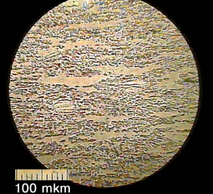
With this setup, mesostructures were obtained [16] that consisted of sintered WC–3Co
granules 40—100 μm in size. The holding time at 1400 °C and 220 MPa was 7 s. The
sintering process proceeded in the presence of the liquid phase. In the course of high pressure
sintering the granules deformed plastically to form a textured mesostructure ( Fig. 1). It is
necessary to note, under these conditions degradation of mesoelements occurs.164 A.F. Lisovsky /Science of Sintering, 43 (2011) 161-173
___________________________________________________________________________
100 μm
Fig.1. Mesostructure of the WC–Co composition [16]
For formation of mesostructures can be used the high technologies of sintering which
apply to formation of nanostructures – hot isostatic pressing (HIP) [17], spark plasma
sintering (SPS) [18], high frequency induction heated sintering (HFIHS) [19], rapid omni
compaction (ROC) [20], pulse plasma sintering (PPS) [21], ultrahigh pressure rapid hot
consolidation (UPRC) [22].
Migration metal melt from intergranular space into mesoelement is the main problem
during formation mesostructure in the first type mesocomposition.
One more promising method to form mesostructures in cemented carbides, in the
author’s opinion, is high temperature treatment of sintered samples with metal melts (MMT–
technology). The MMT–technology is based on the phenomenon of the imbibition of metal
melts by a pore free sintered composition [23]. On penetration of a metal melt into cemented
carbide article the deconsolidation of the high melting skeleton takes place [10]. The process
should proceed purposefully to form aggregates of high melting particles separated with
thicker layers of a binder. In WC–Co cemented carbides, this was accomplished by squeezing
carbide samples before the MMT–process. In this case, the sample deformed elastoplastically
and the high melting skeleton became fragmented at the mesolevel. On subsequent treatment
with metal melts, the liquid phase being imbibed by the sample separated the resulting
fragments with the binder layers. The formation of mesostructures in cemented carbides
which are used as hard facing materials should be highlighted [24]. The authors of [24]
suggested a wear resistant hard facing material which consisted of spherical cast WC/W2C
carbide granules of the eutectic composition, polycrystalline granules formed from crystals of
WC monocarbide, and a matrix material consisting of cobalt, nickel, iron or their alloys. In
the hard facing composition the size of granules was varied from 320 to 640 μm, and the
content of them in the matrix from 15 to 50 mass %. The formation of mesostructures in these
compositions occurs under the nonequilibrium conditions, with high fluxes of energy
delivered into the melting zone and high rate cooling.A.F. Lisovsky /Science of Sintering, 43 (2011) 161-173 165
___________________________________________________________________________
3.2. Features of the formation of the structure in the second type
mesocomposition
The author [25] investigated features of formation of the structure in the second type
mesocompositions on the samples prepared from the WC–6Co F, WC–6Co, WC–6Co C,
WC–20Co cemented carbides (Tab. II).
Tab. II. Composition and structure WC–Co cemented carbides [25]
No Cemented WC, mass % Со, mass % davr WC, μm u∗, vol. %
sample carbides
s
1 WC–6Co F 94.1 5.9 1.1 14.0
2 WC–6Co 94.1 5.9 2.0 14.0
3 WC–6Co C 94.1 5.9 3.2 14.0
4 WC–20Co 79.9 20.1 2.1 42.0
0
∗ at 1400 С
Mesostructured WC–Co cemented carbides were prepared by the traditional method
of hot pressing at 1400°С. Distribution Co binder after hot pressing ascertained by X-ray
spectrum analysis. Researches (Tab. III) have shown, that during liquid phase sintering the
cobalt melt migration occurs, therefore observed redistribution of the Co binder between
mesoelements and a matrix.
Tab. III. Co binder contents in WC–Со mesocompositions [25]
No Mesocomposition* Co binder content in the Co binder content after
samples initial state, mass % hot pressing , mass %
1 WC–6Co F / WC–20Co 5.9 / 20.1 11.3 / 14.4
2 WC–6Co / WC–20Co 5.9 / 20.1 9.8 / 16.0
3 WC–6Co C / WC–20Co 5.9 / 20.1 8.1 / 17.8
4 WC–20Co / WC–6Co 20.1 / 5.9 13.4 / 12.5
* The numerator indicates the mesoelement and denominator indicates the matrix.
The driving force for the migration process of a liquid phase is the gradient of
migration pressure П [26]. The migration pressure П has physical meaning of suction
pressure, therefore the liquid moves from volumes with smaller value of pressure П to
volumes with its greater value [11]. Migration pressure П depends on the liquid phase content
(u) and the WC particle size (d) of a composition [13]:
1
K
(γ ss − 2 gγ sl )⎛⎜ 1 − u ⎞⎟
3
П= (1)
3d ⎝ u ⎠
where g is the coefficient which accounts for variations of particle geometrics during the
period of liquid migration.
Using expression (1), calculated values of pressure П in mesoelements and in
matrixes (Tab. IV) and established that during liquid phase migration the pressure gradient
between mesoelements and a matrix decreases. Knowing value of pressure П, it is possible to
predict a direction of migration cobalt melt in WC–Со mesocompositions and to define its
final state.166 A.F. Lisovsky /Science of Sintering, 43 (2011) 161-173
___________________________________________________________________________
Tab. IV. Pressure П in WC–Со mesocompositions [25]
No Pressure П in the initial Pressure П after hot
samples Mesocomposition* state, МPа pressing , МPа
1 WC–6Co F / WC–20Co 0.64 / 0.18 0.43 / 0.25
2 WC–6Co / WC–20Co 0.53 / 0.18 0.38 / 0.22
3 WC–6Co C / WC–20Co 0.32 / 0.18 0.28 / 0.20
4 WC–20Co / WC–6Co 0.18 / 0.53 0.27 / 0.30
* The numerator indicates the mesoelement and denominator indicates the matrix
To prevent cobalt melt redistribution between mesoelements and a matrix, formation
of structure of a mesocomposition it is necessary produce at temperature below the cobalt
phase melting point. Let's note that it is difficult to produce pore free articles under these
conditions.
The second way of formation of mesostructures consists in preventing mass transfer
of a liquid between mesoelements and a matrix. To achieve this purpose, it is necessary to
cover a mesoelement with a layer which is impenetrable for a liquid phase. For example, a
mesoelement is covered with TiN layer. In this direction positive results are obtained by
authors [27]. It seems perspective to use a combination of materials of a mesoelement and a
matrix which form a dense layer at the mesoelement – matrix interface. For example, in a
composition consisting of WC–6Co mesoelements and W–Fe–Cu matrix, at the
WC–6Co/W–Fe–Cu interface the dense carbide layer is formed (Fig.2). This layer interferes
with penetration of a liquid phase from the W–Fe–Cu matrix into the WC–6Co mesoelements.
WC–6Co
Carbide layer
W–Fe–Cu 20 μm
Fig.2. Structure of the WC–6Co /W–Fe–Cu interface.
3.3. Features of the formation of the structure in the third type mesocomposition
Features of the formation of the structure in the third type mesocomposition we shall
consider on an example of a diamond/WC–Co composition. The diamond/WC–Co
composition prepare on the technology of hot pressing briquettes consisting of powders of
diamond, WC, and Co. The hot pressing is processed at temperature above the Co phase
melting point. To manufacture of these mesocompositions apply also high technologies [28,
29]. During manufacturing a mesocomposition it is necessary to provide good adhesion of
diamond particles and a matrix. To obtain good adhesion of diamond particles and a matrix,
diamond particles cover with a layer of metal, as a rule Co, Ni, Mo. This layer is necessary for
keeping at a surface of a diamond particle during hot pressing. In this connection the problemA.F. Lisovsky /Science of Sintering, 43 (2011) 161-173 167
___________________________________________________________________________
of stability of metal layers in a WC–Co mesocomposition is important. Conditions of stability
of metal layers are given in articles [12, 30]. The author [30], using a thermodynamic method
of research, obtained the following expression for the change in the Helmholtz free energy
(ΔF) which describes process of migration of a liquid from a layer in a matrix.
1
ΔF = (2γ13 − γ11 )ΔS11 + S c γ 34 cos Θ 2 + S 2 γ 34 cos Θ3 , (2)
3
where γ is the surface tension; S is the surface areas; Sc is the cavity surface area; indexes: 1 is
the WC particles, 2 is the diamond crystal, 3 is the liquid phase, 4 is the gas, 11, 13, 23, 14,
24, 34 indicate to which phase or surface a value relates;
γ14 − γ13 γ −γ
cos Θ 2 = , cos Θ3 = 24 23 ; Θ is limiting wetting angle.
γ 34 γ 34
In expression (2) the first term describes energy changes which occur within the
volume of the composition during migration of liquid from the cavity, the second term
describes those in the cavity, and the third those in phase 2. It is noted that in the composition
always Θ 2 < 90° , i.e., cos Θ 2 > 0 . This is a necessary condition for existence of a
composition as a physical object.
From expression (2) follows, that in compositions which exhibit migration pressure
liquid metal interlayers are sTab. with any values of Θ 3 only in a cavity whose size is lees
than the critical size, and they are unsTab. with cavity dimensions greater than the critical size
and also with mesoelements not wetted by liquid, Θ 3 > 90° . If a mesoelement is wetted by
liquid, interlayers are sTab. in the case when their thickness is less than critical δcr determined
from the equality of composite migration pressure and capillary pressure which arises with
substitution of the interlayer by a gas phase. With δ > δcr under these conditions the interlayer
is unsTab.. External pressure (pressure of hot pressing) promotes stability of a metal layer.
During formation of a diamond / WC–Co mesocomposition polymorphic
transformation diamond – graphite occurs. This process takes place at a surface of diamond
crystal therefore the graphite film divided a diamond crystal and a matrix is formed. To
eliminate the graphite film, in a metal layer enter the chemical elements having high affinity
to carbon. Positive results have been achieved at addition Cr, Mo, B [31].
4. Properties
The formation of the mesostructure allows one to produce cemented carbides with
particular properties by varying sizes and compositions of mesoelements, their properties as
well as the content, composition and properties of a cementing bond. Special purpose alloys,
various steels and subsequent heat treatment of an article, dispersion hardened materials, etc.,
are used as a bond.
The most comprehensive findings of an investigation into the effect of the
composition and structure of the mesostructured cemented carbides on the fracture toughness
KIc, hardness HV100 and wear resistance were obtained for the WC–Co cemented carbide [15]
(see Tab. V). The authors of [15] have found that cemented carbides with mesostructure are
characterized by an excellent combination of the fracture toughness and wear resistance
which is far superior to the identical combination of the properties of the commercial WC–Co
cemented carbides. A high fracture toughness ranging up to 37.9 MPa⋅m0.5 was obtained
thanks to rather thick interlayers of a bond between mesoelements, and a high wear resistance
was assured by low cobalt mesoelements.168 A.F. Lisovsky /Science of Sintering, 43 (2011) 161-173
___________________________________________________________________________
Tab. V. Mechanical properties of mesostructured WC–Co cemented carbides [15]
Co, vol% Wear
KIc, MPa⋅m0.5 HV100 resistance, ASTM
Mesoelement Matrix
units*
10 0 10.9 1620 14.8
10 10 17.6 1250 7.3
10 20 23.5 1050 4.7
10 30 34.5 856 4.3
18 0 13.4 1350 4.6
18 10 19.9 1080 3.5
18 20 27.7 899 2.7
18 30 35.7 732 2.0
25 0 16.7 1100 2.5
25 10 22.7 930 1.8
25 20 31.5 804 1.5
25 30 37.9 667 1.4
* ASTM Standard B611. Standard test method for abrasive wear resistance of cemented carbides. In:
R. F. Allen (Ed.), Annual book of ASTM standards, pp 328—329, ASTM, Philadelphia, 1999.
Unfortunately, in Ref. [15], there is no information on such important characteristics
tot
as bending strength Rbm, compression strength Rcm, the total work of deformation Adef , and
plastic deformation ε. The values of these mechanical properties of WC–15Co,Ni were
obtained in [32]. Tab. 6 lists the properties of the WC–15Co,Ni cemented carbide of
homogeneous structure and the properties of the WC–15Co,Ni (MMT) with the mesostructure
obtained by the MMT technology. It should be noted that the WC–15Co,Ni (MMT) samples
consisted of mesoelements from 10 to 20 μm in size separated with interlayers of the cobalt
bond.
Tab. VI. Mechanical properties of cemented carbides [32]
tot
KIc, Rbm, Rcm, Adef , Аpl, εtot,
Sample λ
MPa⋅m0.5 MPa MPa kJ/m 3 kJ/m3 %
WC—15Co,Ni 16.6 2460 3740 114.9 90.1 3.6 4.1
WC—15Co,Ni (MMT) 19.8 2610 3500 165.7 143.6 6.5 4.8
The mean thickness of the Co interlayers in the mesoelements was 0.1 μm, mean size
of WC particles 1.5 μm and the binder content of 8 mass %. The mean thickness of the Co
intergranules was 2 μm. A correlation between mechanical properties of WC–15Co,Ni and
WC–15Co,Ni (MMT) with the mesostructure has shown that the formation of the latter
involved an increase in bending strength, total work of deformation, its plastic component and
plasticity of cemented carbides (Tab. VI). To assess the dissipation of energy delivered to the
material, the energy absorbability coefficient λ was used. It is defined as the ratio between the
plastic and elastic components of the work of deformation (λ = Аpl/Аel) [35]. It follows from
Tab. 6 that mesostructured cemented carbides are characterized by a higher ability to absorb
energy.
From the above stated follows, that at present only limited experimental data on
physic–mechanical properties of cemented carbides with the mesostructure are available.
These data have been obtained using cemented carbides with different mesostructures and
compositions and cannot be used for the construction of correlation maps of cemented carbide
mesostructure–macroproperties relations. This problem can be partially solved by theA.F. Lisovsky /Science of Sintering, 43 (2011) 161-173 169
___________________________________________________________________________
computer–aided modelling of mesostructures and subsequent calculating of physico–
mechanical properties of mesostructured cemented carbides.
To form mesostructures, sintered carbide granules [15], cast granules of the WC–
W2C eutectic composition [24], and granules produced by crushing cemented carbide waste
are used. Granules of the first two types are spherical, those produced by crushing are of
arbitrary shapes with sharp edges and on oxidation in air these particles also acquire the near
spherical shape. This allows authors [34] to suggest the regular structural model of a
mesostructured cemented carbide. The structural unit cell of the model is a combined (two
phase) cube of side a, the surface of a sphere of diameter D is an interface. A part of the
sphere which is inside the cube is a granule of the WC-Co cemented carbide and the rest of
the cube volume is filled with cobalt (Fig. 3). The D value is chosen such that the volume
fraction of the cemented carbide within the cell equals the volume fraction c of cemented
carbide granules in a mesocomposite. Correspondingly, the volume content of cobalt that
bounds granules is VCo = 1 – c. An advantage of the periodic model is the possibility of a
rigorous approach to predicting properties of a composite by the statement and solution of
boundary value problems for a structural cell that at the same time is a representative volume
of a composite. In this case, the problem of the conversion from micro to macrolevel is
eliminated and the reliability is assured of predicting both micro structural fields (of
concentration of stresses, in particular) and the macro characteristics of a composite over the
whole range of variations of properties and volume content of phases. Another but no less
important advantage of the model is its ability to take into account the parameters of the
microstructure like packing of particles of the discrete phase, particle shape, the existence of
zones of the phase interaction, etc. It should be noted, however, that in the known papers on
theoretical analysis, on the basis of the above model of elastic [35] and plastic [36] properties
of dispersion–strengthened composites, the condition of noncontacting and nonintersection of
spherical particles of the discrete phases is assumed, which restricts their volume content to
the c = cmax = 0.52—074 value depending on the mode of packing.
In the mesostructured cemented carbide under consideration, the volume content of
granules of the WC–Co cemented carbide is, however, in the range from 0.6 to 0.95, which is
possible only in the case of D > a, i.e. when granules have finite spots of contact. Such a
material belongs to the category of composites with interpenetrating (cobalt and cemented
carbide) skeletons. Its structural cell is given in Fig. 3 and the whole volume may be obtained
by repeating it in three mutually perpendicular directions. This model is true for the range of
0 < c < 0.95 and the corresponding value of D(c) is defined by solving one of the equations
3
π⎛D⎞
⎜ ⎟ = c, D < a, c < 0.524;
6⎝ a ⎠
3π ⎡⎛ D ⎞ 1 ⎤ π ⎛ D ⎞
2 3
⎢⎜ ⎟ − ⎥ − ⎜ ⎟ = c, D > a, c > 0.524;
4 ⎢⎣⎝ a ⎠ 3 ⎥⎦ 3 ⎝ a ⎠
a
= +
D
I II III
Fig. 3. Unit cell of a model of the mesostructure: structural cell(I), carbide
mesoelement (II), cobalt binder (III) [34].170 A.F. Lisovsky /Science of Sintering, 43 (2011) 161-173
___________________________________________________________________________
At present the finite element method is the most versatile as regards a consideration
of geometrical and physical nonlinearity. This method is used in the work [34] for the solution
of model three dimensional boundary–value problems of elastoplasticity.
Figure 4 shows the curves of the dependence of the effective elastic modulus E* of a
cemented carbide with the mesostructure on the cobalt volume content VCo (Co matrix). We
would like to remind that the VCo value takes no account of cobalt entering into mesoelements
of cemented carbide which is considered as a homogeneous material. As would be expected,
the WC–15Co + Co matrix (see Fig. 4, curve 1) is more pliable as compared to a similar
mesocomposite containing mesoelements of WC–6Co (see Fig. 4, curve 2). In both the cases,
the elastic modulus decreases as VCo increases.
75
70
65 3
E∗, GPa
60 2
55
1
50
45
40
0 0.05 0.10 0.15 0.20 0.25 VCo
Fig. 4. Dependence of the elastic properties of the mesostructured cemented carbide on the
cobalt volume content: 1 — WC–15Co + Co matrix, 2 — WC–6Co + Co matrix, 3 —
homogeneous WC – Co cemented carbides, • — experimental data for WC–6Co, WC–8Co,
WC–10Co, WC–15Co cemented carbides [34].
1
5000
2
4000
3
, MPa
3000 1
2
3
2000
1000
0
0.005 0.010 0.015
Fig. 5. The σ z = f( ε z function for WC–6Co + Co matrix (—) and WC–15Co + Co matrix
(---) mesocompositions: VCo = 0.1 (1), 0.2 (2), 0.3 (3), the dot–dash lines indicate the
trajectories of unloading, coordinates: σ z is the stress, ε z is the deformation [34].A.F. Lisovsky /Science of Sintering, 43 (2011) 161-173 171
___________________________________________________________________________
The effect of the cemented carbide mesostructure on its elastoplastic properties can be
judged from the deformation curves shown in Fig. 5 (up to ε z = 0.02) for the WC–6Co + Co
matrix and WC–15Co + Co matrix mesocompositions. From here on the value of the
deformation ε z is given in fractions of unit. A comparison between curves 1, 2 and 3 shows
that the material becomes more plastic as VCo (Co matrix) increases.
The above data also allow one to assess the level of residual plastic macrostrains
ε zpl , which may be found either by the direct solution of the model boundary–value
problem under the boundary conditions corresponding to unloading, or by the use of
previously obtained data on the effective elastic module (see Fig. 4). The point of intersection
of the trajectory of unloading with the abscissa axis gives the value of the residual plastic
deformation (see Fig. 5).
The development of the theory of strength of mesostructured cemented carbide on the
basis of the model under consideration is one of possible applications of the latter. The
calculated values of the limiting deformation and compression strength are listed in Tab. VII.
Tab. VII. Limiting characteristics of the mesocompositions in compression predicted on the
basis of the suggested model [34]
Co matrix, WC–6Co + Co matrix WC–15Co + Co matrix
VCo εlim, % σcom, GPa εlim, % σcom, GPa
0 1.35 5.10 3.0 3.85
0.1 1.47 4.52 3.2 3.46
0.2 1.58 3.94 3.41 3.11
0.3 1.72 3.43 3.62 2.76
It is seen from the tabulated numerical values that the accepted condition of the
transition of the material to the limiting state predicts an increase in the deformability and a
decrease in the compression strength with increasing the volume fraction of the cobalt phase
similar to those observed in conventional hard alloys. This suggests that the model under
discussion, which is free of simplifying assumptions, is a reliable basis for the development of
advanced theories of strength of cemented carbides of mesostructure.
5. Applications
According to researches [37, 38], mesostructured WC–Co cemented carbides are
highly effective in rock destruction tools – a roller cone drill bit, a percussion or hammer bit,
a drag bit. Using ММТ–process, authors [39] obtained mesostructured WC–TiC–Co
cemented carbide. Because of the establishment of mesoelements cemented by thick layers of
binder metal, the material acquires a higher viscosity. The stresses arising under impact cyclic
loads were thus distributed over a considerable depth compared with conventional WC–TiC–
Co cemented carbide, i.e. an increased volume of material entered into the cutting operation,
this not only having improved physico–mechanical properties, but also being able to absorb a
larger quantity of critical energy. It has allowed increasing mill service life in 3 times [40].
The second type mesostructured compositions can be effective at manufacturing
materials for electric contacts. Good electric conductivity in a combination to high wear
resistance is obtained by the author of the review in the composition consisting of a W–Fe–Cu
matrix and WC–6Co mesoelements. Researchers [31] have produced drag bits comprising
inserts prepared from a diamond / WC–Co mesocomposition. In this mesocomposition at a
surface of diamond particles created the Co layer alloyed with B and Cr. Service life of new
bits were in 2 times more in comparison with conventional drag bits. It is the author’s opinion172 A.F. Lisovsky /Science of Sintering, 43 (2011) 161-173
___________________________________________________________________________
that mesostructured WC–Co cemented carbides can be highly efficient in friction couples.
The above described examples have shown that application of mesocomposite materials is
perspective in rock destruction and metal working tools as well as in mechanical engineering.
6. Conclusions
Analysis of the literature data shows that at present several lines in the formation of
mesostructures in cemented carbides are being developed. They are: sintering in the presence
of the liquid phase, solid-state sintering at pressure, treatment of carbide articles with metal
melts. During liquid phase sintering mesocompositions of the first and second types mean a
problem is penetration metal melt in a mesoelement therefore degradation of structure of a
mesoelement takes place. One of methods of the decision of this problem is creation at a
surface of a mesoelement of a layer which interferes with penetration metal melt in a
mesoelement. Formation of mesostructure of the third type compositions is necessary for
carrying out under the conditions providing good adhesion of a mesoelement and a matrix.
For wide practical application of mesocompositions it is necessary to solve a number
of scientific and technological problems. One of them is development of scientific base of
formation of mesocompositions, prediction of their properties, studying of the mechanism of
occurrence and development of fatigue cracks at a mesolevel, and to find the correlation
between the mesostructure and the macro properties of cemented carbide.
6. References
1. H. E. Exner, Int. Metals Reviews, 4 (1979) 149.
2. B. Roebuck, E. A. Almond, Int. Mater. Reviews, 33 (1988) 90.
3. C. H. Vasel, A. D. Krawitz, E. F. Drake, and E. A. Kenik, Metall. Transac. A, 16A
(1985) 2309.
4. A. F. Lisovsky, In Proc. Powder Metal 1998. World Congress and Exhibition.
Granada, Spain. EPMA (ed), London , 4 (1998) 115.
5. P. R. Fry, G.G. Garrett, J. Mater. Sci., 23(1988) 2325.
6. Z. Fang, J. A. Sue, US Patent 5 880 382 (1999).
7. J. M. Chaix, Materials Science Forum. Sintering Fundamentals, 624 (2009) 1.
8. V.T. Golovchan, N.V. Litoshenko, Int. J. Refrac. Met. Hard Mater, 21 (2003) 241.
9. A. I. Tsitrin, V. Ya. Belousov, Soviet Powd. Metall. and Met. Ceramics, 24 (1985)
237.
10. A. F. Lisovsky, Powd. Met. Int., 19 (1987) 18.
11. A. F. Lisovsky, Int. J. Heat Mass Transfer, 33 (1990) 1599.
12. A. F. Lisovsky, Soviet Powd. Met. Met. Ceramics, 30 (1991) 10.
13. A. F. Lisovsky, Metall. Mater. Transac. A, 25A (1994) 733.
14. A. F. Lisovsky, In Hard Materials Proceedings of the European Conference on Hard
Materials and Diamond Tooling. Beaulieu Congress and Exhibition Lausanne,
Switzerland. EPMA (ed), (2002) 256.
15. X. Deng, B. R. Patterson, K. K. Chawla, et. al., Int. J. Refrac. Met. and Hard Mater.,
19 (2001) 547.
16. A. F. Lisovsky, S. A. Ivanov, and V. P. Pereyaslov, J. Superhard Mater., 25 (2003)
71.
17. I. Azcona, A. Ordonez, J.M. Sanchez, and F. Castro, J. Mater. Sci., 37 (2002) 4189.
18. D. Sivaprahasam, S. B. Chandrasekar, and R. Sundaresan, Int. J. Refract. Met. Hard
Mater., 25 (2007) 144.
19. H.C. Kim, I. J. Shon, I. K. Jeong, at. al., Metal Mater. Int., 13 (2007) 39.A.F. Lisovsky /Science of Sintering, 43 (2011) 161-173 173
___________________________________________________________________________
20. E. M. Dubensky and R.T. Nilsson, US Patent 5 773 735 (1996).
21. A. Michalski and D. Siemiaszko, Int. J. Refract. Metal and Hard Mater., 25 (2007)
153.
22. X. Wang, Z. Fang, H.Y. Sohn, In: Engquist J, editor. Proceedings of the 2007
international conference on powder metallurgy & particulate materials, Denver, USA,
(2007) 8.
23. A. F. Lisovsky, J. Superhard Mater., 27 (2001)1.
24. A. J. Massey and J. L. Overstreet, US Patent. 6 248 149 (2001).
25. A. F. Lisovsky, J. Superhard Mater., 33 (2011) (in press).
26. A. F. Lisovsky, Int. J. Refrac. Hard Metal., 7 (1988) 152 .
27. R E. Toth, I. Smid, A., Sherman, et. al., In Proceedings of the 15th International
Plansee Seminar, Reutte, 2 (2001) 306.
28. A.L.Maistrenko, S.A. Ivanov, V. P. Pereyaslov, and M. N. Voloshin, J. Superhard
Mater., 22 (2000) 36.
29. M. N. Voloshin and V. P. Kolomiets, J. Superhard Mater., 18 (1996) 1.
30. A. F. Lisovsky, Soviet Powd. Metall. Metal Ceramics, 30 (1991) 183.
31. N. A. Bondarenko, N.V. Novikov, V.A.Mechnik, J. Superhard Mater., 26 (2004) 1.
32. A. F. Lisovsky, Powd. Metall. and Metal Ceramics, 40 (2001) 71.
33. A. A. Lebedev and E.V. Chechin, Strength of Materials, 12 (1980) 412.
34. V.I. Kushch, A. F. Lisovsky and S.I. Shestakov, J. Superhard Mater., 25 (2003) 30.
35. A.S. Sangani and W. Lu, J. Mech. Phys. Solids, 35 (1987) 1.
36. G. Bao, J.W. Hutchinson and R.M. McMeeking. Acta Metall. Mater. 39 (1991) 1871.
37. Ponte–Castenda and P.Suquet, Adv. Appl. Mech., 34 (1997) 171.
38. Z.Z. Fand, A. Griffo, B. White, et. al., Int. J. Refrac. Met. Hard Mater., 19 (2001)
453.
39. F. Lisovsky and T.E. Gracheva, Int. J. Refract. Met. Hard Mater. ,11 (1992) 83.
40. A.F. Lisovsky, S.J. Didenko, T. E.Gracheva, Soviet J. Superhard Mater., 11 (1989)
59 .
Садржај: Аутор разматра формирање мезоструктура у цементираним карбидима,
анализира постојеће технологије за њихово добијање, описује физичка и механичка
својства цементираних карбида са мезоструктуром и указује на њихову ефикасност у
обради метала и као алата за дробљење стена.
Кључне речи: цементирани карбид; чврсти метали; структура; мезоструктураYou can also read