Guilin Woodpecker Medical Instrument Co., Ltd.
←
→
Page content transcription
If your browser does not render page correctly, please read the page content below

Guilin Woodpecker Medical Instrument Co., Ltd.
The pictures are only for reference. The final interpretation rights belong to Guilin Woodpecker Medical Instrument Co., Ltd. Woodpecker reserves the right to change
the design of the equipment, the technique, fittings, instruction manual and the content of the original packing list at any time without further notice.
The product were authorized appearance patent, counterfeit will be sued.

Thank you for purchasing Woodpecker Dental Implant Device Implanter. In order to guarantee the correct operation, it is
recommended to read this instruction manual carefully before operation. For convenient reading, it is recommended to put it where is
available at any time.

   Device Type
   1. Type of protection against electric shock: Class I equipment with internal power supply
   2. Degree of protection against electric shock: B type applied part
   3. Recommended disinfection method: See section 6 Cleaning, disinfection, and sterilization
   4. Waterproof protection is in line with the current version IEC60529: host IPX1,foot pedal IPX6.
   5. Degree of safety application in the presence of a flammable anesthetic mixture with air, oxygen, or nitrous oxide: Equipment
cannot be used in the presence of a flammable anesthetic mixture with air, oxygen, or nitrous oxide.
   6. Operating mode: Continuous operation

   Precautions
   1. Please read these precautions before operation and operate in correct way.
   2. The following icons is for ensuring safe operation, preventing you or others from being hurt. These icons are classified by
degree of risk, degree of damage and severity. All indicators should be highly concerned. Please obey the instruction.

                              Classification         Degree of risk, degree of damage and severity
                                 Dangers          Indicating potential personal injury or bodily injury
                                Warnings            Indicating potential slight injury or bodily injury
                               Precautions      Indicating instructions to be observed for ensuring safety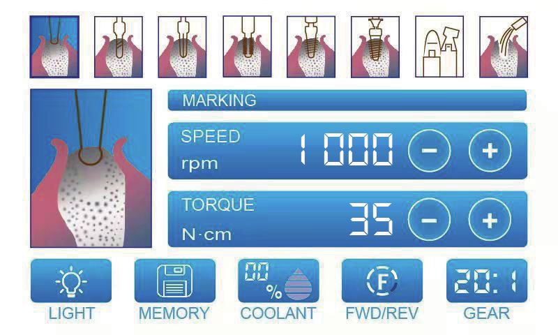
Contents
1. Product introduction.........................................................................................................1
2. Accessories description....................................................................................................3
3. Control of host and foot pedal ........................................................................................4
4. Installation........................................................................................................................7
5. Operation .......................................................................................................................10
6. Clean, disinfection, and sterilization .............................................................................19
7. Error code and solution (error alarm interface).............................................................26
8. Storage and maintenance ..............................................................................................26
9. Symbols.........................................................................................................................28
10. Specifications...............................................................................................................29
11. After-sales service........................................................................................................30
12. Environment protection ..............................................................................................30
13. Statement .....................................................................................................................30
14. Guarantee.....................................................................................................................30
15. EMC-Declaration of comformity.................................................................................32
1. Product introduction
 1.1 Precautions
        Danger
    1. To prevent electric shock, do not use wet hands to pull the power cord; be sure to prevent the control circuit from water; use a
grounded electrical outlet.
    2. Keep it away from explosives and combustibles, with special care not to use this machine for patients who use nitrous oxide
anesthesia.
    3. This equipment may be used only by specialized and suitably trained personnel such as surgeons. The application place of the
device is dental clinic or hospital.If correctly used, this equipment does not give rise to side effects. Improper use, on other hand, will
give rise to transmission of heat to the tissues.
        Warnings
    1. To avoid the risk of electric shock, this equipment must only be connected to a supply mains with protective earth.
    2. Not to position the device to make it difficult to operate the disconnection device.                                                   1
    3. In the presence of electromagnetic interference environment, the planter may be malfunctioning. Do not install the Dental
Implanting Device near equipment that releases magnetic waves. When using ultrasonic vibrating equipment or electrode knife
nearby, close the switch on the control panel.
    4. Implanter requires special precautions for EMC and needs to be installed and put into service according to the EMC
environment.
    5. Device with electromagnetic launcher will affect the normal operation of Implanter, do not run both devices at the same time.
    6. Implanter cannot be used in operating rooms containing potentially flammable gas mixtures.
    7. To avoid possible injury to human or damage to the device, make sure that the motor handpiece (hereinafter simply referred to
as the motor) is completely parked when replacing the planting tool. And the replacement shall be conducted by foot pedal controller.
    8. Severe impact, such as dropping, will lead to damage to the implanting device.
    9. During the work of peristaltic pump, the water pipe cannot be excessive bending or knotting, otherwise the pipe may fracture.
    10. Do not attempt to disassemble the control panel, foot control or motor.
    11. Dental handpieces (hereinafter referred to as handpieces ) should be cleaned, lubricated and disinfected immediately after use.
    12. Do not lubricate the motor. Lubricating oil can cause overheating, resulting in damage to the motor. Control panel and multi-
function pedals cannot be disinfected.
    13. Do not clean control panel with dissolving solution.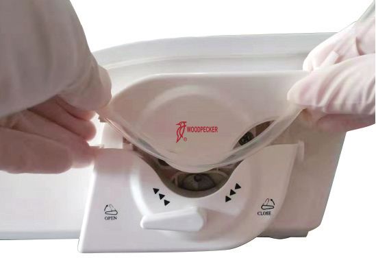
14. The motor cable cannot be removed from motor.
        15. Switch off electrical power after each use.
             Precautions
        1. If you need to repair and purchase spare parts, please contact the authorized supplier.
        2. It is recommended to use the original pre-disinfection disposable water pipe combination.
        3. The accuracy of torque monitoring depends on the accuracy of the handpiece installed on the micro motor. If the handpiece
    produced by other manufacturers is used, the actual torque value may not be displayed correctly. To ensure that the actual torque
    matches the displayed torque, please use the matched handpiece.
        4. Please read this instruction manual before operation and master parts of functions.
        5. Check the operating status of Implanter before use and confirm that there is no abnormal condition.
        6. Test the Implanter before operation to ensure correct operation.
        7. If there is a permanent malfunction (excessive vibrations, noise, heat production, etc.) on the Implanter, please immediately
    close it and return it to the authorized dealer.
2       8. If the frequency of use is very high, please consider storing some spare parts.
        9. Please cut off the power before cleaning the control panel with a damp cloth.
        10. Dispose water pipe after operation with the method of disposing medical waste.
        11. The operation mode of Implanter is continuous operation mode, i.e., there will be 10 minutes pause after 3 minutes' operation.
    If there is no system overheating, it will prevent the patients, users or the third party from hurt. The user should be responsible for the
    use and shutdown of system.
        This instruction manual is intended to indicate the safety requirements, installation procedures, proper methods of use and proper
    maintenance of the equipment. If you encounter any unexpected problems, please contact Service Center of Guilin Woodpecker
    Medical Instrument Co., Ltd.
        The manufacturer will not be responsible for any personal injury or property damage caused by device tampering or modification
    conducted by unauthorized person.
        Woodpecker reserves the right to change the design of the equipment, the technique, fittings, instruction manual and the content of
    the original packing list at any time without further notice. The pictures are only for reference. The final interpretation rights belong to
    Guilin Woodpecker Medical Instrument Co., Ltd.
        Guilin Woodpecker Medical Devices Co., Ltd. will continue to update its products, thus bring changes in device components. If
    there is any difference between your manual and the description on your product, please contact the authorized distributor or after-
    sales service center of Guilin Woodpecker Medical Instrument Co., Ltd. for explanation.
This manual is strictly prohibited from being used in any way other than installation, use and maintenance of the equipment.
1.2 Contraindications and precautions
1.2.1 The hemophilia patient is forbidden to use this equipment.
1.2.2 The patients and doctors with heart pacemaker are forbidden to use this equipment.
1.2.3 Heart disease patients and children should be cautious to use the equipment.
1.2.4 Patients with oral and maxillo-facial infection, oral mucosal diseases, periapical disease, gingivitis, periodontitis, or mouth
neoplasm should be cautious to use this equipment.
1.2.5 Patients with allergic constitution and drug allergy history are forbidden to use this equipment.
1.2.6 People with mental disorders should be cautious to use this equipment.
1.2.7 Patients with severe systemic infection or systemic diseases such as the diseases of heart, liver, kidney, hematopoietic system,
digestive system and endocrine system should be cautious to use this equipment.
8. Pregnant women, lactating women, and women have a plan of birth should be cautious to use this equipment.
1.3 Scope of use
This product is intended for use in dental surgery, thus other uses are not allowed. There will be potential danger if it is used for 3
other purposes!
1.4 Safety requirement
Guilin Woodpecker Medical Instrument Co., Ltd. will NOT be responsible for any direct or indirect damages and losses under the
following conditions:
The equipment is used for any purpose that is not mentioned in the scope of use.
The operator does not follow the steps and requirements in instruction manual to use the device.
The cabling system of the room where the device is used does not meet the appropriate standards and the appropriate requirements.
Assemble, operate and repair the device without authorization of manufacturer.
The environment in which the device is located or stored does not meet the requirements mentioned in technical requirements
section of the instruction manual.
2. Accessories description
Please refer to packing list for device configuration.3. Control of host and foot pedal
3.1 Control of host keys
3.1.1 Working interface and control of keys
41. Light key Motor LED switch; circular touch to control the on/off of LED.
2. Store key Store key; click to store setting specifications.
3. Water control key Click to select water volume. Six water gear, including 00%, 20%, 40%, 60%, 80%, and 100%. Circularly
press the key to select.
4. Forward/reverse rotation
Used to select the direction of rotation; direction changes for each pressing.
5. Speed ratio key
Used to set the gear ratio with handpiece; repeatedly pressing till the LCD correctly displays gear ratio with handpiece.
6. Torque control key
Used to set torque range of motor; “+” for increase, while “-” for decrease. Press and hold to accelerate the speed change.
7. Speed control key
Used to set rotating speed of motor; “+” for speed up, while “-” for slow down. Press and hold to accelerate the speed change.
8. Program key
Touch the icons to choose corresponding programs. Please refer to the Clause 5.1 for the functions of each program.
5
3.1.2 Interface of restoring the factory settings
Whether to restore the
factory settings?
Yes No
Figure 1 Restore factory setting interface
While starting up, press the foot pedal at the same time. The factory reset menu will pop up as shown in the picture. When "YES"
is selected, the saved parameters will be cleared and the original factory setting parameters will be restored. When "No" is selected,
the factory settings will not be restored and the system will boot normally.3.1.3 Error alarm interface
Error 01
The foot is not connected!
Please check whether the
foot is in good contact.
Figure 3 Error alarm interface
As shown in Figure 3, the warning 0x indicates alarm number. Please refer to section 7 Error code and solution for specific number
and the corresponding content.
3.2 Foot pedal control
6
1. Water volume adjustment button
Used for choosing 6 cooling water flow levels. The water level is incremented each time the button is stepped. At the maximum
level 6, pressing once to loops back to level 1.2. Program switchover button
Used for choosing needed programs. The program is changed each time the button is stepped. At the Program 8, pressing once
to loops back to Program 1. Short press Program button to move forward to next program, and long press (>2s) to move back to last
program.
3. Forward / reverse rotating direction
Used for changing the rotating direction of contra-angle. The direction will change after stepping.
4. Speed control foot pedal
Used to start/stop the motor and control the speed during operation. The operating speed of motor is controlled by the foot of
operator. After lifting the foot, the displayed data will change to the maximum setting value.
4. Installation
4.1 Safety requirements during installation
Danger: Equipment is installed on the premise that the installation must meet the appropriate standards and related electrical
safety requirements. 7
Danger: Never install the device in an explosion-hazardous area and the device must not be operated in areas with flammable
gases (anesthetic mixture, oxygen, etc.).
Danger: Installation site should be able to protect device from shocks and splashing of water or other liquids.
Danger: Do not install the device near or above a heat source. It must be installed in a well-ventilated area with sufficient
space around it, especially the exhaust fan and back.
Warning: Do not directly expose the parts to the sun or UV light source.
Warning: The device is movable. Be careful while handling it.
Warning: Before connecting the cord to the device, make sure the joint is dry. If necessary, dry it with air gun.4.2 Accessories connection
Figure 4
4.2.1 Installation of foot pedal:
Connect the foot pedal plug to the foot pedal socket and tighten those two fixing screws (Figure 4 - E)
8 4.2.2 Power cord installation:
Plug the power cord output into the power supply socket of the device (Figure 4 - D)
4.2.3 Installation of infusion bottle holder:
Insert the infusion bottle holder into the fixing hole on the right rear of the shell; (Figure 4 - A)
4.2.4 Installation of infusion bottle:
Hang the infusion bottle (The infusion bottle contains purchased normal saline injection.) on its holder.
4.2.5 Installation of motor:
Plug the tail cord of motor into the output socket on the front of the device (Note: align the red marking point). (Figure 4 - B)
Figure 54.2.6 Peristaltic pump tube installation:
A.Turn the peristaltic pump knob anticlockwise (The direction is as indicated by the arrow above "CLOSE") to the "OPEN"
indicator and open the pump head (Figure 5-A).
B.Place the tube in the impeller of the peristaltic pump (Figure 5 - B).
C.Turn the peristaltic pump knob clockwise (The direction is as indicated by the arrow above "OPEN") to the "CLOSE" position
and close the pump head (Figure 5 - D).
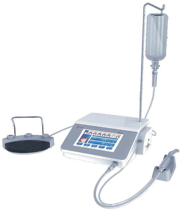
4.2.7 Complete machine effect after installations of all accessories: (Figure 6)
9
Figure 6
4.2.8 Switch on (Figure 4 - C) ; start to use the machine as it display normally:
Step on the pedal after the parameters such as speed, torque and water are set properly. The device starts to work. When the pedal
is released, the device stops working.5. Operation
5.1 Program
5.1.1 Choice of programs
Implanter owns 8 programs. There are two ways to choose program:
1. Touch the corresponding icons on the screen.
2. Step on the “Program switchover” button on the foot pedal.
10
5.1.2 Function description of programs
The function of each program is as shown as follow:
Icon Function Description
Positioning Accurate positioning on the alveolar bone by using a positioning drill.
Hole-drilling Determine the direction and depth of hole-drilling.Hole-
Determine the diameter of the hole.
broadening
Tapping Make a thread on the hole to match the implant.
Implanting Implant dental implants into alveolar bone.
Lock the
Screw the nut onto the dental implant.
abutment screw 11
User defined Change straight handpiece, contra-angle with different speed ratios for different
mode dental procedures.
Cleaning Water discharging without motor rotation is convenient for flushing.
5.1.3 Factory Settings
Before delivery, several parameters mainly including speed, torque, speed ratio and water output have been set according to the
actual application. These parameters can be changed within the range of parameters specified in the current program.The range of different parameters and their factory settings are as shown in the table below:
Icon Function Speed/ rpm Torque/ N·cm Speed ratio Water output/%
Positioning 200-2500 1000(D) 5-80 35(D) 16:1,20:1, 27:1,20:1(D) 60
Hole-drilling 200-2500 800(D) 5-80 35(D) 16:1,20:1, 27:1,20:1(D) 60
Hole-broadening 200-2500 600(D) 5-80 35(D) 16:1,20:1,27:1,20:1(D) 60
12 Tapping 15-100 20(D) 5-80 35(D) 16:1,20:1, 27:1,20:1(D) 60
Implanting 15-100 20(D) 5-80 35(D) 16:1,20:1, 27:1,20:1(D) 0
Lock the abutment
15-100 20(D) 5-15 10(D) 16:1,20:1, 27:1,20:1(D) 0
screw
1:1,1:2,1:3, 1:5,16:1,
User defined mode 15-40000 1200(D) 5-80 45(D) 60
20:1,27:1, 20:1(D)
Cleaning —— —— —— 80
Note: the letter “D” stands for default value.5.2 Default parameter adjustment
Within specified range, the adjustable parameters are as follow:
1. Maximum speed
2. Maximum torque
3. Water output
4. Speed ratio
5.2.1 Maximum speed adjustment
13
Touch the “Speed” (+, -) key to adjust motor speed. The speed will change each time after touching the “Speed” key. Long press
the “Speed” key to accelerate the change of speed setting value.5.2.2 Maximum torque adjustment
14 Touch the “Torque” (+, -) key to adjust maximum torque output of motor. The torque will change each time after touching the
“Torque” key. Long press the “Torque” key to accelerate the change of torque setting value.
5.2.3 Water output adjustmentTouch the “Water volume” key on the screen to adjust. There are 6 water levels. The water level will change to the next level after
each touch.
15
Step on the blue “Water volume adjustment” button to adjust water volume.
5.2.4 Speed ratio adjustment
Adjust by pressing the "Speed Ratio" button to match the gear ratio of the handpiece to be used.5.3 Motor rotating direction adjustment
16 Touch the key shown above to change the rotating direction of motor.
Step on the “Forward/reverse rotation” during operation to change the rotating direction of motor.
5.4 Motor LED adjustmentTouch the “LED” button to for setting to determine the on or off state of LED while stepping on foot pedal. The state of LED will change once after each touch. Only the device with LED owns this function. 17 5.5 Save the parameters After finishing the above steps, press “Store” key. You will hear a beep if the parameters are saved.
5.6 Standard operation
         1. After installation of corresponding accessories, connect to the power supply, and turn on the power supply. After booting, the
     displayed interface is default to be Program 1.

        2. Touching screen or stepping on the “Program switchover” button on the foot pedal to choose the program.

18

         3. Confirm that the speed, torque, water flow, forward/reverse rotation, speed ratio and other parameters of corresponding program
     meet the requirements.
         4. Step on the foot pedal, and then motor starts to rotate. Deep step to accelerate; the maximum speed value is the current program
     speed setting value; light step to reduce the speed; the minimum trigger speed is15 rpm (Gear ratio of handpiece: 20:1). After fully
     release, the speed restore to the set value speed.
5. Torque protection will start as the torque reaches preset value. Meanwhile, the motor slows down to stop, preventing from generating excessive torque. Release foot pedal to remove torque protection. Step again, and the motor will rotate under preset torque 19 value. 6. Release foot pedal, and the motor stop rotating. 6. Clean, disinfection, and sterilization If there is blood or salt residue on the main unit and foot controller, unplug the power cord, wipe it off with a damp cloth, and wipe with a soft cloth dampened with alcohol. The contra-angle handpice and the motor hanpiece can be disinfected with heat sterilizers. Plug in motor disinfection stopper before disinfection the motor hanpiece! Warning: Never place the main unit and foot controller in a washer-disinfector, autoclave or ultrasonic bath. Warning: If you use a disinfectant in the form of a spray, never spray the devices and accessories directly. Warning: Only use surface disinfectants that are certified by officially recognized institutes, do not contain chlorine and have been declared aldehyde-free.
Warning:
         Clean and disinfect the main unit and foot controller regularly. When subjecting the main unit and foot controller to cleaning and
     disinfection ensure that the charging cable is not connected and that the charging socket is closed.
         Warning:
         Only the following parts can be sterilized:
         Contra-angle handpice and its kit, motor hanpiece, handpiece holder, motor disinfection stopper, pipe clamp, O-ring.
       The cleaning, disinfection and sterilization of the contra-angle handpice and the motor
     hanpiece are as follow.
         Unless otherwise stated, they will be hereinafter referred to as “products”.
         Warnings:
         The use of strong detergent and disinfectant (alkaline pH>9 or acid pH
1. Wipe all visible surfaces of the device with a disposable soft cloth, including motor handpiece, water bottle hooks, pedals, and
cables. And then dry them after washing;
2. Wipe all visible surfaces of the device including motor handpiece, water bottle hooks, pedals and cables with a disposable soft
cloth dampened with disinfectant to ensure that all surfaces are wet. Let the disinfectant work during a specified period of time and
then dry the surface;
3. Dry all the cleaned and disinfected parts thoroughly in the air indoors.
Cautions:
(1) Do not automatically clean the main unit.
(2) Do not use metal brushes.
6.4 Preparation before cleaning:
Steps:
Tools: tray, a disposable soft cloth, a disposable soft cloth dampened with disinfectant,motor disinfection stopper
1. Remove the motor handpiece from the main engine and put the motor handpiece into a clean tray.
2. Please plug the motor disinfection stopper in the motor handpiece. 21
6.5 Cleaning:
The cleaning should be performed no later than 24 hours after the operation.
The cleaning can be divided into automated cleaning and manual cleaning. Automated cleaning is preferred if conditions permit.
Automated cleaning:
The parts that can be cleaned automatically are as follow: contra-angle handpice.
• The cleaner is proved to be valid by CE certification in accordance with EN ISO 15883.
• There should be a flushing connector connected to the inner cavity of the product.
• The cleaning procedure is suitable for the product, and the irrigating period is sufficient.
• Do not clean the product with ultrasound.
It is recommended to use a washer-disinfector in accordance with EN ISO 15883. For the specific procedure, please refer to the
automated disinfection section in the next section "Disinfection".
Manual cleaning:
The parts that need to be cleaned Manually are as follow: motor handpiece.
Manual cleaning steps:
1. Wet the soft cloth completely with distilled water or deionized water, and then wipe all the surfaces of the handpiece and mainunit until the surface of them is not stained.
2. Wipe the surface of the handpiece and main unit with a dry soft nap-free cloth.
3. Repeat the above steps at least 3 times.
Notes: Use distilled water or deionized water for cleaning at room temperature.
Precautions:
(1) The cleaning agent does not have to be pure water. It can be distilled water, deionized water or multi-enzyme. But please ensure
that the selected cleaning agent is compatible with the product.
(2) In washing stage, the water temperature should not exceed 45 °C, otherwise the protein will solidify and it would be difficult to
remove.
(3) After cleaning, the chemical residue should be less than 10mg / L.
6.6 Disinfection:
Disinfection must be performed no later than 2 hours after the cleaning phase. Automated disinfection is preferred if conditions
permit.
22 Automated disinfection-Washer-disinfector:
The parts that can be disinfected automatically are as follow: contra-angle handpice.
• The washer-disinfector is proved to be valid by CE certification in accordance with EN ISO 15883.
• Use high temperature disinfection function. The temperature does not exceed 134 ° C, and the disinfection under the temperature
cannot exceed 20 minutes.
• The disinfection cycle is in accordance with the disinfection cycle in EN ISO 15883.
Cleaning and disinfecting steps by using Washer-disinfector:
1. Carefully place the product into the disinfection basket. Fixation of product is needed only when the product is removable in the
device. The products are not allowed to contact each other.
2. Use a suitable rinsing adaptor, and connect the internal water lines to the rinsing connection of the washer-disinfector.
3. Start the program.
4. After the program is finished, remove the product from the washer-disinfector, inspect (refer to section "Inspection and
Maintenance") and packaging (refer to chapter "Packaging"). Dry the product repeatedly if necessary (refer to section "Drying").
Precautions:
(1) Before use, you must carefully read the operating instructions provided by the equipment manufacturer to familiarize yourself
with the disinfection process and precautions.
(2) With this equipment, cleaning, disinfection and drying will be carried out together.(3) Cleaning:
(a) The cleaning procedure should be suitable for the product to be treated. The flushing period should be sufficient (5-10
minutes). Pre-wash for 3 minutes, wash for another 5 minutes, and rinse it for twice with each rinse lasting for 1 minute.
(b) In the washing stage, the water temperature should not exceed 45 °C, otherwise the protein will solidify and it is difficult to
remove.
(c) The solution used can be pure water, distilled water, deionized water or multi-enzyme solution, etc., and only freshly
prepared solutions can be used.
(d) During the use of cleaner, the concentration and time provided by manufacturer shall be obeyed. The used cleaner is
neodisher MediZym(Dr.Weigert).
(4) Disinfection:
(a) Direct use after disinfection: temperature ≥ 90 ° C, time ≥ 5 min or A0 ≥ 3000;
Sterilize it after disinfection and use: temperature ≥ 90 ° C, time ≥ 1 min or A0 ≥ 600
(b) For the disinfection here, the temperature is 93 ° C, the time is 2.5 min, and A0>3000
(5) Only distilled or deionized water with a small amount of microorganisms (6.7 Drying:
If your cleaning and disinfection process does not have an automatic drying function, dry it after cleaning and disinfection.
Methods:
1. Spread a clean white paper (white cloth) on the flat table, point the product against the white paper (white cloth), and then dry
the product with filtered dry compressed air (maximum pressure 3 bar). Until no liquid is sprayed onto the white paper (white cloth),
the product drying is completed.
2. It can also be dried directly in a medical drying cabinet (or oven). The recommended drying temperature is 80℃ ~ 120℃ and
the time should be 15 ~ 40 minutes.
Precautions:
(1) The drying of product must be performed in a clean place;
(2) The drying temperature should not exceed 138 °C;
(3) The equipment used should be inspected and maintained regularly.
6.8 Inspection and maintenance:
24 In this chapter, we only check the appearance of the product. Make sure the inspection is correct.
1. Check the product. If there is still visible stain on the product after cleaning/disinfection, the entire cleaning/disinfection process
must be repeated.
2. Check the product. If it is obviously damaged, smashed, detached, corroded or bent, it must be scrapped and not allowed to
continue to be used.
3. Check the product. If the accessories are found to be damaged, please replace it before use. And the new accessories for
replacement must be cleaned, disinfected and dried.
4. If the service time (number of times) of the product reaches the specified service life (number of times), please replace it in time.
6.9 Packaging:
The disinfected and dried product quickly package in a medical sterilization bag (or special holder, sterile box).
Precautions:
(1) The package used conforms to ISO 11607;
(2) It can withstand high temperature of 138 °C and has sufficient steam permeability;
(3) The packaging environment and related tools must be cleaned regularly to ensure cleanliness and prevent the introduction of
contaminants;
(4) Avoid contact with parts of different metals when packaging.6.10 Sterilization:
Use only the following steam sterilization procedures (fractional pre-vacuum procedure*) for sterilization, and other sterilization
procedures are prohibited:
1. The steam sterilizer complies with EN13060 or is certified according to EN 285 to comply with EN ISO 17665;
2. The highest sterilization temperature is 138 ° C;
3. The sterilization time is at least 4 minutes at a temperature of 132 ° C / 134 ° C and a pressure of 2.0 bar ~ 2.3 bars.
4. Allow a maximum sterilization time of 20 minutes at 134 °C.
Verification of the fundamental suitability of the products for effective steam sterilization was provided by a verified testing
laboratory.
Precautions:
(1) Only products that have been effectively cleaned and disinfected are allowed to be sterilized;
(2) Before using the sterilizer for sterilization, read the Instruction Manual provided by the equipment manufacturer and follow the
instructions.
(3) Do not use hot air sterilization and radiation sterilization as this may result in damage to the product; 25
(4) Please use the recommended sterilization procedures for sterilization. It is not recommended to sterilize with other
sterilization procedures such as ethylene oxide, formaldehyde and low temperature plasma sterilization. The manufacturer assumes
no responsibility for the procedures that have not been recommended. If you use the sterilization procedures that have not been
recommended, please adhere to related effective standards and verify the suitability and effectiveness.
* Fractional pre-vacuum procedure = steam sterilization with repetitive pre-vacuum. The procedure used here is to perform steam
sterilization through three pre-vacuums.
6.11 Storage:
1. Store in a clean, dry, ventilated, non-corrosive atmosphere with a relative humidity of 10% to 93%, an atmospheric pressure of
70KPa to 106KPa, and a temperature of -20 °C to +55 °C;
2. After sterilization,the product should be packaged in a medical sterilization bag or a clean sealing container, and stored in a
special storage cabinet. The storage time should not exceed 7 days. If it is exceeded, it should be reprocessed before use.
Precautions:
(1) The storage environment should be clean and must be disinfected regularly;
(2) Product storage must be batched and marked and recorded.6.12 Transportation:
1. Prevent excessive shock and vibration during transportation, and handle with care;
2. It should not be mixed with dangerous goods during transportation;
3. Avoid exposure to sun or rain or snow during transportation.
The cleaning and disinfection of main unit are as follows.
• Before each use, wipe the surface of the machine and the tail cord of the motor handpiece with a soft cloth or paper towel soaked
in 75% medical alcohol. Repeat the wipe for at least 3 times.
• After each use, wipe the surface of the device and the tail cord of the motor handpiece with a soft cloth soaked in clean water
(distilled or deionized water) or a clean disposable wipe. Repeat the wipe for at least 3 times.
7. Error code and solution (error alarm interface)
When there is a problem with the operation, the display will provide the error code of the problem diagnosis: Specifically, switch
to the error prompt interface for explanation and solution to the problem:
26 Error code Error description Solution
Please ensure the foot pedal is connected. If the alarm is not eliminated, please
Error 01 Foot pedal is not connected contact our local distributor or us.
The power supply voltage is unstable. Please ensure that the grid voltage is stable.
Error 02 Motor voltage error If the alarm is not eliminated, please contact our local distributor or us.
The motor handpiece is not connected when the machine is turned on. Make
sure that the motor handpiece and the main unit are properly connected and then
Error 03 Power-on failure power on again. If the alarm is not eliminated, please contact our local distributor
or us.
The handpiece is not connected Please check if the handpiece is in good contact. If the alarm is not eliminated,
Error 04 please contact our local distributor or us.
Error 05 Motor error Please contact our local distributor or us.
Error 06 The circuit is abnormal Please contact our local distributor or us.
Error 07 Operation failure Please check if the parameter settings are normal.
8. Storage and maintenance8.1 The device should be handled carefully and lightly. Be sure that it is far from the vibration, and installed or kept in a cool, dry,
and ventilated place.
8.2 Do not store the machine together with articles that is poisonous, combustible, caustic, or explosive.
8.3 This device should be stored in a room where the relative humidity is not more than 10%~93%, atmospheric pressure is
70kPa~106kPa, and the temperature is-20℃ ~ +55℃.
8.4 Turned off power switch and unplug the power plug when the device is not in use. If it is not used for a long time, please get
through to power supply and water for five minutes once per month.
8.5 Check the integrity of cable. If it is damaged, please replace it with original accessories.
8.6 After each operation, the contra-angle shall be cleaned, applied oil, and disinfected as per requirements. If it is not used for a
period, please clean it, apply oil to it, and disinfect is at least once a week.
Replacement of fuse
Power supply shall be cut off while intending to conduct the following operations. And disconnect power supply cable and main
power supply. (See Figure 7 - Refer to B)
27
Figure 7
1. Danger: Switch off the apparatus.
2. Insert a flat-blade screwdriver to the groove under the power supply hole, and then pry it out (Figure 7 - ref. A);
3. Pull out the fuse compartment (see Figure 7 - Ref. B) and select the appropriate fuse for replacement by following the label
on the bottom of the power supply socket.
8.7 The maintenance personnel appointed by the manufacturer can obtain the equipment maintenance-related data (such as circuit
diagrams, component lists, etc.) from the manufacturer.9. Symbols
Mark Follow Instructions for Use
Use indoor only Alternating current
Socket for the foot switch Caution mechanical injury
Manufacturer Date of manufacture
Drip-proof Strong water spraying experiment
28
Type B applied part Can be autoclaved
Caution Protective earthing
Serial number Humidity limit for storage
Atmospheric pressure for storage Temperature limit for storage
Appliance complies with WEEE directive CE marked product
Parts with water line Water flow directionPosition of the knob when the peristaltic pump is on and the direction in which the knob can be rotated in the
current state
Position of the knob when the peristaltic pump is off and the direction in which the knob can be rotated in the
current state
Authorised Representative in the EUROPEAN COMMUNITY
Note: Please refer to product packaging label for production date.
10. Specifications
10.1 Host specifications
Model: Implanter
Device for intermittent operation: 3 min ON,10 min OFF 29
Power supply voltage: 200-240V~
Power supply frequency: 50/60Hz
Software version: Implant-V1
Input power: 150VA
Fuses: 2×T1.6AL 250V
Applied parts: Contra-angle handpiece
Maximum Temperature: 41.8℃
Maximum water volume: 135ml/min
Dimension: 276mm*267mm*110mm
Operation environment:
Environment temperature: +5~40℃
Relative humidity: 30%~75%
Atmosphere pressure:70kPa~106kPa
Device case material: PC+ABS
Handpiece material: brass10.2 Motor specifications:
Model: SPM58L, SPM58NL, SPM58, SPM58LS
Rotating speed range: 300-40,000 rpm
Torque range: 5-80 Ncm(ratio: 20:1)
Input voltage: DC27V
Dimension: Maximum diameter 21.5 mm, Length 110 mm
Tail cord length: 1.8m
10.3 Foot pedal controller specifications
Model: MF4
Tail cord length: 2.8m
11. After-sales service
Since the date of sale, the device enjoys one year of free warranty, and our company is responsible for the lifetime maintenance.
30 Irreparable damage to device caused by non-designated professional maintenance personnel does not belong to the scope of free
warranty.
12. Environment protection
The device does not contain any harmful ingredients. It can be handled or destroyed in accordance with the relevant local
regulations.
13. Statement
Woodpecker reserves the right to change the design of the equipment, the technique, fittings, instruction manual and the content of
the original packing list at any time without further notice. The pictures are only for reference. The final interpretation rights belong to
Guilin Woodpecker Medical Instrument Co., Ltd.
14. Guarantee
14.1Before being put into market, all woodpeckers device should be thoroughly inspected to ensure proper use.
14.2Woodpecker promised that for any new products purchased from authorized distributors or importers of Woodpeckers,
if ill function is resulted from the quality problem, you are entitled to free replacement during the warranty period:• One year since the date of purchasing equipment;
• One year since the date of purchasing motor and tail cord.
14.3 During the warranty period, Woodpecker will repair or replace the damaged parts of the device for free.
14.4 Woodpeckers will not be responsible for any direct or indirect damage and loss if:
14.4.1 The equipment is used for any purpose other than the mentioned scope of use.
14.4.2 The operator does not follow the steps and requirements stipulated in the instruction manual to use the device.
14.4.3 The cabling system of the room where the equipment is used does not meet the appropriate standards and the appropriate
requirements.
14.4.4 The device is installed, operated, or repaired by the unauthorized personnel.
14.4.5 The environment where the device is used and stored does not meet the requirements stipulated in relevant section of
instruction manual.
14.5 Damage caused by transportation, incorrect use, or negligence will be excluded from the warranty. And if the parts are
tempered by unauthorized, the warranty card losses effect. 31
14.6 Warnings
To request a warranty, please send your device, warranty card, and invoice for the device to your Woodpecker distributor / importer
within the warranty period. In order to be repaired during the warranty period, the purchaser shall return the repaired product to the
distributor / importer at their expense.
14.7 Parts must be properly packaged (or in original packaging) while being sent back.
14.8 All parts must be accompanied by the following information
14.8.1 Buyer information, including phone numbers, etc.;
14.8.2 Distributor or importer information;
14.8.3 A copy of the photo of the goods, date of purchase, problem of part, part name and serial number;
14.8.4 Description of the problem.
14.9Any damage caused during transportation is not under warranty. If the problem is caused by incorrect use, the repair fee
should be undertaken by the users.15. EMC-Declaration of comformity
The device has been tested and homologated in accordance with EN 60601-1-2 for EMC. This does not guarantee in any way that
this device will not be effected by electromagnetic interference Avoid using the device in high electromagnetic environment.
Technical Description Concerning Electromagnetic Emission
Table 1: Declaration - electromagnetic emissions
Guidance and manufacturer’s declaration - electromagnetic emissions
The model Implanter is intended for use in the electromagnetic environment specified below. The customer or the user of the model Implanter
should assure that it is used in such an environment.
Emissions test Compliance Electromagnetic environment - guidance
The model Implanter uses RF energy only for its internal function. Therefore, its RF
RF emissions
Group 1 emissions are very low and are not likely to cause any interference in nearby electronic
CISPR 11
equipment.
32
RF emissions
Class B
CISPR11
The model Implanter is suitable for used in all establishments, including domestic
Harmonic emissions
Class A establishments and those directly connected to the public low-voltage power supply network
lEC 61000-3-2
that supplies buildings used for domestic purposes.
Voltage fluctuations / flicker emissions
Complies
lEC 61000-3-3
Technical Description Concerning Electromagnetic Immunity
Table 2: Guidance & Declaration - electromagnetic immunity
Guidance & Declaration — electromagnetic immunity
The model Implanter is intended for use in the electromagnetic environment specified below. The customer or the user of the model Implanter
should assure that It is used in such an environment.
IEC 60601
Immunity test Compliance level Electromagnetic environment - guidance
test level
Electrostatic discharge ±8kV contact ±8kV contact Floors should be wood, concrete or ceramic tile. If floors
(ESD) ±2, ±4, ±8, ±15kV air ±2, ±4, ±8, ±15kV air are covered with synthetic material, the relative humidity
lEC 61000-4-2 should be at least 30 %.Electrical fast transient/
±2kV for power supply lines Mains power quality should be that of a typical
burst ±2kV for power supply lines
±1kV for Input/output lines commercial or hospital environment.
IEC 61000-4-4
±0.5, ±1kV line to line
Surge ±0.5, ±1kV line to line Mains power quality should be that of a typical
±0.5, ±1, ±2kV line to earth
lEC 61000-4-5 ±0.5, ±1, ±2kV line to earth commercial or hospital environment.
95% dip in UT.)
for 0.5 cycle
for 0.5 cycle
95% dip in UT.) commercial or hospital environment. If the user of the
for 1 cycle
variations on power supply for 1 cycle models Implanter requires continued operation during
70% UT
input lines 70% UT power mains interruptions, it is recommended that the
(30% dip in UT)
IEC 61000-4-11 (30% dip in UT) models Implanter be powered from an uninterruptible
for 25 cycles
for 25 cycles power supply or a battery. 33
95 % dip in UT)
for 250 cycles
for 250 cycles
Power frequency (50/60
Hz) Power frequency magnetic fields should be at levels
magnetic field 30A/m 30A/m characteristic of a typical location in a typical commercial
lEC 61000-4-8 or hospital environment.
NOTE UT is the a.c. mains voltage prior to application of the test level.
Table 3: Guidance & Declaration - electromagnetic immunity concerning Conducted RF & Radiated RF
Guidance & Declaration - Electromagnetic immunity
The model Implanter is intended for use in.the electromagnetic environment specified below. The customer or the user of the models Implanter
should assure that it is used in such an environment.
Immunity test IEC 60601 test level Compliance level Electromagnetic environment - guidancePortable and mobile RF communications equipment should be used no closer to any
part of the models Implanter, including cables, than the recommended separation
distance calculated from the equation applicable to the frequency of the transmitter.
Recommended separation distance
d=1.2×P1/2
Conducted RF 3 Vrms
d=2×P1/2
lEC 61000-4-6 150 kHz to 80 MHz
3V d=1.2×P1/2 80 MHz to 800 MHz
Conducted RF 6 Vrms
6V d=2.3×P1/2 800 MHz to 2.7 GHz
lEC 61000-4-6 ISM frequency band
3V/m where P is the maximum output power rating of the transmitter In watts (W) according
Radiated RF 3 V/m
to the transmitter manufacturer and d Is the recommended separation distance in
lEC 61000-4-3 80 MHz to 2.7 GHz
meters (m).
Field strengths from fixed RF transmitters, as determined by an electromagnetic site
survey,a should be less than the compliance level in each frequency range.b
Interference may occur In the vicinity of equipment marked with the following
symbol:
34 NOTE 1 At 80 MHz end 800 MHz. the higher frequency range applies.
NOTE 2 These guidelines may not apply in all situations. Electromagnetic propagation is affected by absorption and reflection from structures,
objects and people.
a Field strengths from fixed transmitters, such as base stations for radio (cellular/cordless) telephones and land mobile radios, amateur radio, AM and
FM radio broadcast and TV broadcast cannot be predicted theoretically with accuracy. To assess the electromagnetic environment due to fixed RF
transmitters, an electromagnetic site survey should be considered. If the measured field strength in the location in which the model Implanter is used
exceeds the applicable RF compliance level above, the model Implanter should be observed to verify normal operation. If abnormal performance is
observed, additional measures may be necessary, such as reorienting or relocating the model Implanter.
b Over the frequency range 150 kHz to 80 MHz, field strengths should be less than 3V/m.
Table 4: Recommended separation distances between portable and mobile RF communications equipment and the model Implanter
Recommended separation distances between
portable and mobile RF communications equipment and the model
Implanter
The model Implanter is intended for use in electromagnetic environment in which radiated RF disturbances is controlled. The customer or the
user of the model Implanter can help prevent electromagnetic interference by maintaining a minimum distance between portable and mobile
RF communications equipment (transmitters) and the model Implanter as recommended below, according to the maximum output power of the
communications equipment.Rated maximum Separation distance according to frequency of transmitter output power m of transmitter 150kHz to 80MHz 80MHz to 800MHz 800MHz to 2,7GHz W d=1.2×P1/2 d=1.2×P1/2 d=2.3×P1/2 0,01 0.12 0.12 0.23 0,1 0.38 0.38 0.73 1 1.2 1.2 2.3 10 3.8 3.8 7.3 100 12 12 23 For transmitters rated at a maximum output power not listed above, the recommended separation distance d in meters (m) can be estimated using the equation applicable to the frequency of the transmitter, where P is the maximum output power rating of the transmitter in watts (W) accordable to the transmitter manufacturer. NOTE I At 80 MHz and 800 MHz. the separation distance for the higher frequency range applies. NOTE 2 These guidelines may not apply in all situations. Electromagnetic propagation is affected by absorption and reflection from structures, objects and people. 35
ZMN-SM-018 V1.7-20210112
You can also read