Hedgehog: Handheld Spherical Pin Array based on a Central Electromagnetic Actuator
←
→
Page content transcription
If your browser does not render page correctly, please read the page content below
Hedgehog: Handheld Spherical Pin Array based on a Central
Electromagnetic Actuator
Aline Abler1 , Juan Zárate1 , Thomas Langerak1 , Velko Vechev1 and Otmar Hilliges1
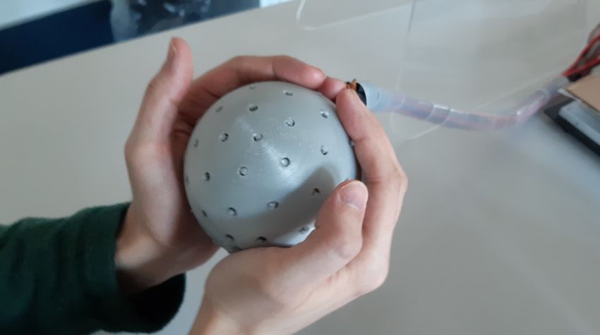
Abstract— We present Hedgehog, a single-actuator spherical
pin-array device that produces cutaneous haptic sensations to
the user’s palms. Hedgehog can enrich digital experiences by
providing dynamic haptic patterns over a spherical surface
using a simple, hand-held device. The key to our design is that
it uses a single central actuator, a spherical omnidirectional
electromagnet, to control the extension of all the 86 movable
pins. This keeps our design simple to fabricate and scalable.
A core challenge with this type of design is that the pins
in the array, made out of permanent magnets, need to have
a stable position when retracted. We present a method to
compute such an arrays’ spatial stability, evaluate our hardware
implementation in terms of its output force and pin’s extension
and compare it against our method’s predictions. We also
report our findings from three user studies investigating the
perceived force and speed of traveling patterns. Finally, we Fig. 1. The Hedgehog Pin Array Haptic Interface, consisting of 86 haptic
present insights on the possible applications of Hedgehog. pins distributed over a 10 cm diameter spherical pin array. A central omni-
directional electromagnet repels passive magnets attached to the haptic pins,
I. I NTRODUCTION causing them to push outwards against the user’s palms. To stabilize the
system, the design contains a number of non-movable shielding magnets.
Handheld devices are a popular way to interact with
virtual content and to receive tactile information [1], [2].
They require minimal instrumentation and offer a familiar compared to traditional pin array interfaces. The use of 3-
interaction paradigm of intuitive handling and exploration of DoF omnidirectional electromagnets in haptic feedback has
everyday objects [3]. However, such devices rely primarily been explored previously [15], [16]. However, it should be
on vibrotactile actuators that are limited in their ability to noted that these examples focus on graspable interactions;
stimulate the full range of human mechanoreceptors [4]. here we present a haptic display based on moving pins.
Pin array haptic interfaces offer a way to increase the For the design of such a handheld EM-driven interface, we
fidelity and localization of haptic feedback on the user’s make the following considerations. As we seek to maximize
hand. They come in the form of touchable surfaces [5]– pin-density and force-output, we must consider the passive
[8], wearables [9], [10], and embedded in handheld plat- magnet’s arrangement on the surface, their size, and the
forms [11]–[14]. It is desirable to provide varying levels cross-talk magnetic interaction between them. Furthermore,
of force intensity as it allows for a larger dynamic range we need to select these factors such that the array is
when rendering tactile stimuli. However, this adds mechan- magnetically stable in the “off” position. To this end, we
ical complexity to the system, making the dense pin-array build-up a magnetic model for estimating passive magnetic
handheld form-factor challenging to achieve. forces, enabling the design of optimal arrangements and
Instead, we propose a novel way to continuously actuate parameter selection. We show that our technique can also
dense arrays of pins using a single omnidirectional electro- accommodate irregularities in such spherical topologies. The
magnetic actuator. In such a configuration, the pins are sim- model’s predicted behavior is shown to be in-line with
ple passive magnetic elements leveraging the three degrees- the fabricated prototype, the pin-array shown in Figure 1.
of-freedom afforded by the central electromagnet [15]. This Specifically, we make the following contributions:
allows us to adjust the pin force in a particular activated • A novel method of evaluating the mutual interaction of
region dynamically and enables the rendering of various passive magnets in non-planar arrays, including a model
haptic patterns on the device’s surface [10], [11]. By using a validation that shows consistent predictions across 4
single actuator with passive actuated elements, we can con- arrangements, tested experimentally.
struct an interface with high pin-density, able to continuously • A spherical handheld controller that renders tactile
control the force over an affected area, while significantly feedback to the user’s palms via passive magnetic pins.
simplifying the manufacturing and operation of our device • A hardware characterization of the maximum pin force
1 All authors are with the Department of Computer Science of ETH
and extension, as well as perceptual studies on the
Zürich, Switzerland. Aline Abler: ablera@student.ethz.ch. minimum force, force sensitivity, and pattern speed
Others: first.lastname@inf.ethz.ch sensitivity.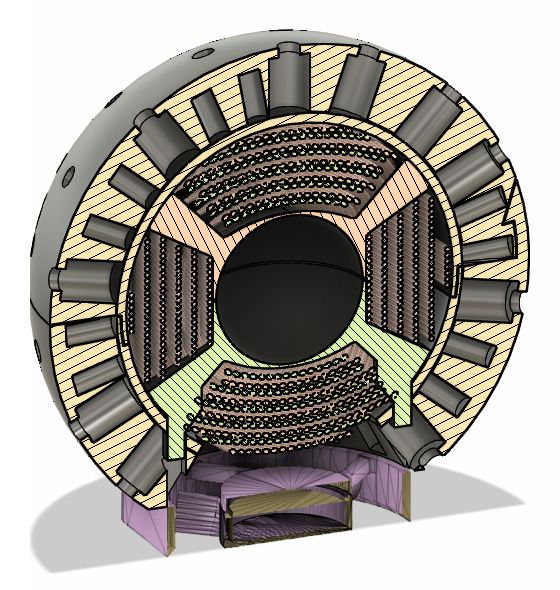
II. D EVICE CONCEPT AND FORCE MODELING
   Our haptic interface leverages a single central omni-
directional electromagnet (EM) to actuate its pins, which
are attached to passive magnets (see Fig.2). All the passive
movable magnets face their north pole inwards. The EM is
activated such that its north pole points towards a speci-
fied direction, represented with a red arrow on Figure 1’s
schematic. Under activation, the EM repels the magnet at
the targeted location, pushing its pin into the user’s skin. If
the objective is a dynamic pattern, the EM adapts its direction
and intensity over time to point to exactly where the stimulus
is needed.
   We choose a spherical-shell topology as it maximizes the
EM’s ability to induce force homogeneously in all pins. Since
all pin magnets need to be oriented the same way, they                            Fig. 2. Exploded view and cross-section of the prototype design. Magnets
                                                                                  are inserted from the inside and held in place with a thin hemispherical shell,
repel each other, and the arrangement tends to be unstable.                       which in turn encases the electromagnet. The inner shell has a diameter of
Therefore, we introduce non-moving magnets as shielding                           70mm. The cavities allow for 0.2mm of tolerance around the magnets.
oriented in the opposite polarity and interspersed with the
pin magnets. If we tune the design correctly, the entire
array becomes stable with the pins automatically retracted                           Our approach to calculate Fm relies on three observations.
by default, thus requiring no power. However, while we                               1) We can use the principle of magnetic field superpo-
seek a stable configuration in the off state, we also wish to                     sition, as there is no influence of ferromagnetic materials2 .
maximize the overall pin-density and the force-output of the                      This allows us to sum up partial magnetic forces between
array when the EM is active. Thus, the pin and shielding                          pairs of magnets to obtain an overall result. 2) For any given
magnets’ sizes and placement in an chosen arrangement                             magnet, most of the other elements within the array are
represent a design trade-off. Given that the stability of each                    sufficiently far, so the approximation of magnetic dipoles can
magnet depends on the contributions of all its neighbors, we                      accurately estimate the magnetic force interaction [17]. The
need to consider:                                                                 advantage is that the dipole model provides a closed-form
   • The EM can induce larger forces in bigger and stronger                       solution. 3) For the few remaining magnet pairs that are too
     magnets, but small magnets allow compact designs and                         close together to use the dipole model, it is feasible to utilize
     denser pin arrays.                                                           FEA (Finite Element Analysis) simulations.
   • Larger shielding magnets easily retain the pin magnets                          We leverage the fact that magnet positions are constrained
     in their resting position, but the shielding has to be weak                  to a sphere surface. We consider the function fsa ,sb (α, o) that
     enough to be overcome by the electromagnet, whose                            calculates the radial force acting between a pair of passive
     magnetic force output is limited by overheating.                             magnets with sizes sa and sb given their relative angle α
   • A denser pin array provides more contact points for the                      and the radial offset of the first magnet o. For large α, we
     user; however, it aggravates magnetic cross-talk issues                      utilize the dipole model (f (dip) ). For small α, we first use a
     due to the closer magnet proximity.                                          selection of angles α for which we simulate the interaction
   We briefly describe below the essential elements consid-                       using FEA. Then, we create a piece-wise linear interpolation
ered to compute each movable pin’s induced radial force,                          of f (f ea) (α, o) for each o, from which we can sample an
how we experimentally validated this model, and its appli-                        approximate result for any α. In sum, we calculate the force
cation for optimizing our design.                                                 between two magnets in the array with the form,
                                                                                                            (
A. Modeling of the magnetic force interaction                                                                 f (f ea) sa ,sb (α, o) α < 30◦
                                                                                           fsa ,sb (α, o) =                                     (1)
   The goal is to determine whether a given magnet ar-                                                        f (dip) sa ,sb (α, o) otherwise.
rangement, characterized by the magnets’ positions, sizes,
and polarities, has a stable resting position. For this, it is                       This method allows us to calculate Fm using only a small
necessary to understand the relation between the force1 Fm                        number of computationally expensive FEA simulations. For
induced by all magnets on a test magnet m, and m’s vertical                       this work, we used Comsol Multiphysics with its magnetic
offset o. If a stable rest position exists: a) Fm becomes zero                    modules. The function fsa ,sb (α, o) is parameterized by the
at that point; and b) Fm is a restoring force as the magnet                       strengths of the magnets a and b, and the size of the sphere.
is disturbed out of that resting position, meaning that if the                       Knowing the locations of the magnets in an arrangement,
displacement is outwards, Fm pushes the magnet back in,                           we use Eq. 1 to compute the total radial force Fm induced
and vice versa. If these two conditions are satisfied, the test                   on magnet m by all other magnets in the arrangement M ,
magnet has a stable resting position.
                                                                                     2 We verified with FEA simulations that the EM’s core is far enough so
  1 Only   the radial force is of interest, as lateral movement is constrained.   that its passive influence in the array becomes negligible.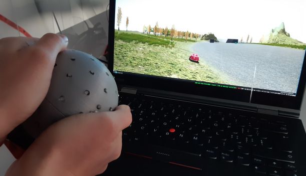
1.5
2 2
1.00
1 1 1.0
Force [N]
0.75
force [N]
force [N]
Force [N]
0.50
0 0 Computation
0.5
0.25 Computation Measurement 1
−1 −1 Measurement Measurement 2
0.00 0.0
−2 0 2 4 6 8 10 12 −2 0 2 4 6 8 10 12 0 5 10 15 20 25 0 5 10 15 20 25
offset [mm] offset [mm] Magnets inserted Magnets inserted
(a) Fm (o) on cD (b) Fm (o) on tkD (a) cD, 3mm shielding magnets (b) cD, 4mm shielding magnets
3 Computation
1.5 Computation
Measurement Measurement
2
Force [N]
Force [N]
1.0
0.5 1
(c) cD polyhedron (d) tkD polyhedron
0.0 0
0 1 2 3 4 5 6 0 1 2 3 4 5 6
Fig. 3. Examples of our approximated function Fm (o) for two different Magnets inserted Magnets inserted
magnet arrangements. Both examples have a stable resting position, as the (c) tkD, 3mm shielding magnets (d) tkD, 4mm shielding magnets
function crosses zero. For tkD, the magnets are in closer proximity, so the
slope of the restoring force is more pronounced. Fig. 4. Validation of our approximation method through measurements.
We measure as well as simulate the radial force Fm (0) as more magnets
are inserted into a testing rig. The average accuracy of our model is 81%.
This difference can be explained by inaccuracies in the vertical placement
as the magnet m is moved vertically by offset o, of the central magnet in our test setup by approx. ±0.25 mm, resulting in
X a range of forces indicated with light blue. In (b), the measurement was
Fm (o) = fsm ,smi (angle(m, mi ), o) ∗ j(m, mi ) interrupted on the first attempt, so a second, equivalent measurement was
mi ∈M \m performed.
(2)
with j(m, mi ) checking if the magnets’ poles face the sphere
equally, pushing force of the central magnet. Neighbor magnets are
( inserted one-by-one, all with the same polarity, while the
1 if ma and mb have same orientation sensor records the force value. In Figure 4 we present the
j(a, b) = (3)
−1 otherwise. result for four different sample arrangements. Our prediction
By inspecting the function Fm (o), we can predict whether on the force agrees fairly well with the measurements. The
magnet m has a stable resting position within M and how normalized root-mean-square deviation for these four exper-
far it will extend when a given force is applied. Figure 3 iments is 19% without any need for curve fitting adjustment.
shows two examples for specific magnet arrangements. Both Some uncertainties in our experimental setup, such as a
arrangements have a zero-force stable position. Also, the vertical offset in the test magnet, may explain the difference.
curve slopes for offsets in the range 0-2 mm show that the C. Parameter selection
less dense array, named cD, would result in softer restoring
forces, in opposition to the denser array tkD. We choose the magnet’s arrangement and the size of the
The radial force Fm (o) may not be precisely the same shielding magnets using our force approximation method.
for each pin magnet in an array. With our method, we To calculate the force which the EM exerts on a movable
can investigate the behaviour of each individual pin magnet pin, we follow a similar approach to the one described in
separately. Our method does not make assumptions on the [15]. The central 3-DoF EM can provide omnidirectional
magnets’ precise positioning and thus does not require the forces or torques, although we are only interested in the
magnet arrangement to have a strict symmetry. We can thus radial component here, inwards and outwards, as all other
apply the same method to arrays with irregularities, e.g., pin movement are constrained. The pin magnets are chosen
with particular locations omitted to make room for a fan to minimize their size while maximizing the force that can
mount, a handle, or control electronics. Since the forces at the be induced in them by our EM. We found the best choice to
boundary of such irregularities would be very different from be Neodymium rod magnets with 4 mm in radius and 10 mm
the regular part of an arrangement, we can evaluate whether in height. All Neodymium magnets used have a remanence
pins on the border still behave similarly to the remaining of Br = 1.35T .
ones. In sum, this method allows to efficiently validate the We choose a hexagonal arrangement for pin and shielding
behavior of regular and irregular arrays and find variants magnets, locating the moving magnets on the center of each
in which all pins have a stable resting position and behave face and the shielding magnets on the vertices. We fold the
similarly when electromagnetic forces are applied. planar hexagons into the spherical shape using icosahedral
Goldberg polyhedra [18]. Polyhedra of this class consist of
B. Method validation mostly hexagons and few pentagons, which allows for an
To validate our method’s generality and accuracy, we arrangement with relatively few irregularities. The desired
tested the interaction force experimentally in different sample pin density can then be chosen by selecting from topologies
arrangements and compared the results to our model. The with a different number of faces. In Figure 3 we show two
experiment setup consisted of a 3D-printed rig that holds examples of such configurations, cD and tkD. We found the
magnets in a specific arrangement, while a force sensor best arrangement of magnets to be one based on the Goldberg
(FSAGPNXX1.5LCAC5, Honeywell) measures the outwards polyhedron tkD. It provides the highest magnet density while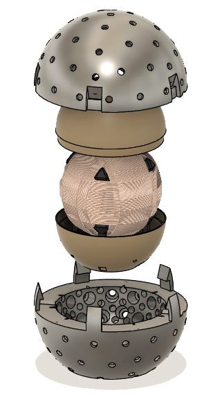
0.20
                                                                                                                               15A
                                    Electromagnet current [A]                                                                  10A
                            0     5             10            15                                  0.15
                                                                                                                               5A

                                                                                      Force [N]
                                                                                                  0.10
                    0.2
    pin force [N]

                                                                             (b)                  0.05

                    0.1                                                                           0.00
                                                                                                         n0   n1   n2    n3   n4
                                                                                                                   Pin
                                                               Model
                    0.0
                                                               Experiments
                                                                                   Fig. 6. Activation spread for the neighbors of target pin (n0) at different
                     −0.1   0.0    0.1      0.2   0.3    0.4     0.5   0.6         activation currents. As, according to our user study in section IV, users can
                                         pin extension [mm]
                                                                             (c)
                                                                                   only feel forces stronger than 30 mN (dotted line), pins with force values
                           (a)                                                     below that can be considered deactivated.
Fig. 5. Results of hardware characterization measurements of pin force and
extension, including comparison to calculated results from our method (sec-
tion II). The modeled relation between force and pin extension corresponds
well to our measurements.                                                          B. Activation spread
                                                                                      As we use a single central EM to operate all pins, this
still having a stable resting position, as validated by our                        configuration does not allow us to actuate a single pin in
method. The shielding magnets have a radius of 2 mm,                               isolation. Even if the magnetic field is pointed at a specific
as smaller magnets are not able to retain the pin magnets                          pin, neighboring pins will react to this actuation, albeit less
according to our method.                                                           strongly. As a result, there is always an area of activated
                                                                                   pins. The activation of a neighbor pin increases with higher
        III. H ARDWARE I MPLEMENTATION & T ESTS
                                                                                   actuation currents but decays with the cosine of the angle
   For the array’s fabrication, we embedded the pin and                            between that neighbor and the target location. Figure 6
shielding magnets in a plastic casing that only allows the                         shows the activation spread for various levels of current and
pin magnets to move vertically (see Figure 1). Haptic pins                         neighbor angular positions.
made of cut acrylic push the user’s skin when their respective
magnet is actuated. In Figure 2 we present an exploded view                                                   IV. U SER E VALUATION
of our device. Of the 86 pins on the final design, the average                        We test our device’s different perceptual characteristics,
human hand covers approximately 30.                                                mainly in terms of force and speed, to give a context of
   In terms of the EM itself, our prototype implementation                         the interaction possibilities that it allows. For this purpose,
reuses the three-axis electromagnet from Omni [15] as its                          we designed a three-part user study to answer the following
central actuator. It also inherits Omni’s cooling system and                       research questions regarding our prototype:
control electronics. The device can be operated indefinitely
                                                                                     A) What is the minimum force users can perceive?
at 5 A of actuation, and excursions up to 15 A (maximum
                                                                                     B) What is the force sensitivity of users in terms of JND
current) are possible for periods of 30 seconds. For details
                                                                                        (just noticeable difference)?
on the EM actuator please refer to [15].
                                                                                    C) What is the pattern speed sensitivity of users in terms
A. Pin’s force and extension                                                            of JND?
   The maximum force and displacement of the individual                               The measured results inform our application design and
pins are two of the main physical characteristics that define                      allow for a comparison between our device and similar work.
our device’s haptic capabilities. The former can be measured
at zero displacement, the latter at zero load, and we describe                     Overall Procedure
each of these tests below. To determine the maximum force a                           We recruited 10 participants (3 female) aged 22 to 55 to
pin exerts, we mounted a force sensor (see Section II-B) on                        perform the three tests. For all experiments, users were asked
top of one of the pins as shown in Figure 5(b). We measure                         to place their dominant hand on top of the device, which
the force for EM actuation currents varying from 0 A to 10 A.                      would play a dynamic circular pattern (Figure 7). Participants
As the EM’s field increases linearly with the current, so does                     were required to wear noise-canceling headphones to mask
the induced force in the magnet. We found for our specific                         the small sound emitted by the prototype.
hardware configuration a force-to-current ratio of 12.6 mN A ,                        Each part of the user study consisted of a number of
corresponding to 200 mN at maximum actuation. The pin                              blocks. We use a two-up-one-down weighted adaptive stair-
extension without load was measured using photographs (see                         case procedure [19] to determine the intensity level at which
Figure 5(c)). We average multiple photos for each of the                           a user has an 80% probability of detecting device activation
actuation values tested: 5, 10 and 15 A. Results for pin                           (Experiment A) or correctly identifying the test stimulus
extension and force are combined in a single plot in Figure 5.                     (Experiments B and C). The parameters for each experiment
The experimental results are compared with the calculated                          are given in Table I. The test parameter D is set to the initial
forces from subsection II-A, showing an excellent agreement                        value Di in the first block. D is increased by the step size
between our model and the experiments. Given the slope in                          ∆D after each negative or incorrect response, and decreased
Figure 5 and the magnet mass (4 gr) we obtain 50 Hz for                            by 0.5488 ∗ ∆D after two consecutive positive or correct
the resonant frequency: below it the pins respond following                        responses. After the first R1 reversals, ∆D is halved, and
the EM actuation.                                                                  after the next R2 reversals, it is halved again. The experiment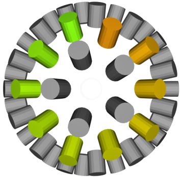
Experiment    Reference level    Di      ∆D      R1     R2    R3                                      Experiment A                        Experiment B   Experiment C
       A              N/A           5A       1A      5      5     5
       B          5A (63 mN)       100%     20%      3      3     4                                                                    100
                                                                                                  0.04
       C            10 pin/s       100%     40%      3      3     4
                                                                                                                                       80
                               TABLE I                                                            0.03

                                                                                      Force [N]

                                                                                                                             JND [%]
 PARAMETERS FOR THE WEIGHTED ADAPTIVE STAIRCASE PROCEDURE .                                                                            60

                                                                                                  0.02
                                                                                                                                       40

                                                                                                  0.01
                                                                                                                                       20

                                                                                                  0.00                                  0
                                                                                                    Force Abs. Thresh. [N]                   Force JND [%] Speed JND [%]

                                                                           Fig. 8. JND study results. Individual averages are indicated as black dots.
                                                                           The bars denote the average of averages, and the error bars denote the
                                                                           standard deviation. JND results are given in percent of the reference level
                                                                           (the Weber fraction).

Fig. 7. JND study setup and schematic of the circular pattern used. The
schematic shows the positions of pin magnets, seen from above. Pins 1-10
are activated sequentially by the electromagnet in the depicted order.

terminates after R3 more reversals with the final ∆D. The
average of all but the first two reversal points is calculated
for each participant.
A. Minimum Force Threshold
                                                                           Fig. 9. A user enjoying the racing game demo. Directional haptic feedback
   Method: Each experiment block contains one trial, during                is given when the car crashes into an obstacle to inform the user where the
which the device is activated, playing the dynamic circular                crash occurred (relative to the car). The pin force scales with the impact
                                                                           velocity.
pattern for five seconds at a speed of 10 pin/s using the test
force D. Participants were told that during some trials, the
device might not activate at all. Participants had to indicate
                                                                           to determine speed differences than the force’s JND. For
whether they thought the device had been activated. Results:
                                                                           example, one participant reported that they perceived the
As a primary finding, participants could sense activation
                                                                           slower patterns as smooth circles, while the faster ones
forces as low as 30 mN (i.e., an actuation current of 2.1
                                                                           seemed more ”random”. The exhibited JND allows for
A), which gives a lower bound for perceivable force.
                                                                           several levels of speed rendering, and its possible that other
B. JND of Force                                                            patterns may exhibit different levels of sensitivity [10].
   Method: Each experiment block contains two trials each.
During each trial, the device is activated, playing a dynamic                                                    V. A PPLICATIONS
circular pattern for five seconds at a speed of 10 pin/s. One
trial plays the reference stimulus, the other does the test                   To explore our haptic device’s usage as a handheld con-
stimulus, in which the activation force is increased w.r.t. the            troller, we integrated a wireless IMU sensor (Xsens MTw
reference stimulus by a force difference D. The trials within              Awinda) and connected it as a controller for a racing game.
a block were randomly ordered, and participants had to                     Our device can improve upon vibrotactile actuation by in-
indicate which trial used a stronger activation force. Results:            dicating a collision event together with the localization of
Participants were able to distinguish force differences of 13%             where it occurred. We performed an informal tryout session
on average, which at the reference stimulus corresponds to                 of this application with two participants, after which we
a difference of 8 mN. We estimate that it should be possible               recorded their feedback (Figure 9). Participants thought the
for users to distinguish roughly ten different levels of force             haptic feedback added by our prototype improves immersion.
within the device’s operational range.                                     They were particularly impressed by feedback when the
                                                                           car flipped upside down and tumbled after some daring
C. JND of Speed                                                            maneuvers.
   Method: Analogous to Part B, but the test stimulus differs                 We have also built a basic application to test our device
from the reference stimulus in pattern speed. Participants                 in a constant-use setting, in which the pins are actuated in
were asked to identify the trial using a faster speed. The                 the upwards direction as the user rotates the device freely.
activation force is constant across trials at 63 mN (or 5                  Such a mechanism could be useful in a navigation task for
A of actuation), this being the highest level of indefinitely              the visually impaired, with the device pointing in a desired
sustainable force output without overheating. Results: Par-                direction. We found that at the device’s peak force output
ticipants were able to distinguish pattern speed differences               of 200 mN, the direction is easier to distinguish than at the
of 47% on average. Overall, it was harder for participants                 continuously sustainable 63 mN.
VI. D ISCUSSION AND C ONCLUSION                                                      R EFERENCES
   We presented a handheld, spherical haptic display based on       [1] Sony, “DualSense,” https://www.playstation.com/en-us/accessories/
                                                                        dualsense-wireless-controller/, accessed: 16.02.2021.
passive moving magnets and a single central electromagnetic         [2] HTC       Vive,     “Controller,”    https://www.vive.com/us/accessory/
actuator. To explore the array’s spatial design, we leveraged           controller/, accessed: 16.02.2021.
a model to predict its mechanical behavior with a sufficient        [3] R. L. Klatzky, S. J. Lederman, and V. A. Metzger, “Identifying objects
                                                                        by touch: An “expert system”,” Perception & psychophysics, vol. 37,
degree of accuracy. We used this approach to build a 10 cm              no. 4, pp. 299–302, 1985.
diameter prototype with 86 active pins. In terms of the force-      [4] R. S. Johansson and J. R. Flanagan, “Coding and use of tactile signals
displacement of output our device, the tests confirm what we            from the fingertips in object manipulation tasks,” Nature Reviews
                                                                        Neuroscience, vol. 10, no. 5, p. 345, 2009.
found using our model: up to 200 mN of haptic force at max          [5] D. Leithinger, S. Follmer, A. Olwal, and H. Ishii, “Physical telep-
load or 0.5 mm displacement with zero-load (see Figure 5).              resence: shape capture and display for embodied, computer-mediated
   As shown in our user study, these numbers resulted in a              remote collaboration,” in Proceedings of the 27th annual ACM sympo-
relatively large dynamic range for users to perceive, allowing          sium on User interface software and technology, 2014, pp. 461–470.
                                                                    [6] J. Jung, E. Youn, and G. Lee, PinPad: Touchpad Interaction with
us to render up to 10 distinguishable levels of force. We               Fast and High-Resolution Tactile Output. New York, NY, USA:
found a lower bound of 30 mN for perceptible force. It is               Association for Computing Machinery, 2017, p. 2416–2425. [Online].
important to note that bi-stable pin-array designs such as              Available: https://doi.org/10.1145/3025453.3025971
                                                                    [7] K. Zhang, E. J. Gonzalez, J. Guo, and S. Follmer, “Design and
those used in [9], [10], and in general, devices that cannot            analysis of high-resolution electrostatic adhesive brakes towards
render varying levels of force, would miss out on the rich,             static refreshable 2.5d tactile shape display,” EEE Trans. Haptics,
dynamic range perceived by users. While we did not conduct              vol. 12, no. 4, p. 470–482, Oct. 2019. [Online]. Available:
                                                                        https://doi.org/10.1109/TOH.2019.2940219
a direct study on localization on the surface, the high pattern-    [8] Y. Ujitoko, T. Taniguchi, S. Sakurai, and K. Hirota, “Development of
speed JND showed that the device output is limited in                   finger-mounted high-density pin-array haptic display,” IEEE Access,
this respect. The maximum extension of a single pin (0.5                vol. 8, pp. 145 107–145 114, 2020.
                                                                    [9] F. Pece, J. J. Zarate, V. Vechev, N. Besse, O. Gudozhnik, H. Shea, and
mm) would seem sufficient in communicating a pin location.              O. Hilliges, “Magtics: Flexible and thin form factor magnetic actuators
However, one limitation of our approach is that nearby pins             for dynamic and wearable haptic feedback,” in Proceedings of the 30th
would also be activated (See Fig. 6), possibly reducing                 annual ACM symposium on User interface software and technology,
                                                                        2017, pp. 143–154.
users’ sensitivity in speed discrimination. Activation spread      [10] V. Vechev, J. Zarate, D. Lindlbauer, R. Hinchet, H. Shea, and
could be addressed in future works, for example, by using               O. Hilliges, “Tactiles: Dual-mode low-power electromagnetic actuators
electrostatic friction [7], [20] to individually break passive          for rendering continuous contact and spatial haptic patterns in vr,” in
                                                                        2019 IEEE Conference on Virtual Reality and 3D User Interfaces
pins by surrounding them with a dielectric material.                    (VR). IEEE, 2019, pp. 312–320.
   In terms of pin-density, we found that despite stronger         [11] H. Benko, C. Holz, M. Sinclair, and E. Ofek, “Normaltouch and tex-
magnetic interactions, dense arrays are suitable for our                turetouch: High-fidelity 3d haptic shape rendering on handheld virtual
                                                                        reality controllers,” in Proceedings of the 29th Annual Symposium on
actuation mechanism. We achieved a stable configuration                 User Interface Software and Technology, 2016, pp. 717–728.
based on the tkD polyhedron, which is the densest within the       [12] S. Yoshida, Y. Sun, and H. Kuzuoka, “Pocopo: Handheld pin-
Goldberg polyhedra class for our sphere size. Arrangements              based shape display for haptic rendering in virtual reality,” in
                                                                        Proceedings of the 2020 CHI Conference on Human Factors in
based on other polyhedra (e.g., quad spheres) are conceivable           Computing Systems, ser. CHI ’20. New York, NY, USA: Association
and might achieve a yet higher pin density. Our magnetic                for Computing Machinery, 2020, p. 1–13. [Online]. Available:
force approximation method can be used to judge different               https://doi.org/10.1145/3313831.3376358
                                                                   [13] D. K. Chen, J.-B. Chossat, and P. B. Shull, “Haptivec: Presenting
arrangements’ suitability, both regular and irregular. The              haptic feedback vectors in handheld controllers using embedded tactile
technique can be used for different sphere sizes and could be           pin arrays,” in Proceedings of the 2019 CHI Conference on Human
generalized to other shapes of passive magnet arrays. While             Factors in Computing Systems, 2019, pp. 1–11.
                                                                   [14] E. Strasnick, J. Yang, K. Tanner, A. Olwal, and S. Follmer, “shiftio:
small enough to be picked up and used as a handheld device,             Reconfigurable tactile elements for dynamic affordances and mobile
our current implementation’s 1.2 kg weight means that it                interaction,” in Proceedings of the 2017 CHI Conference on Human
has to be held with both hands. A stronger electromagnet                Factors in Computing Systems, 2017, pp. 5075–5086.
                                                                   [15] T. Langerak, J. J. Zárate, D. Lindlbauer, C. Holz, and O. Hilliges,
with a more efficient cooling system could achieve the same             “Omni: Volumetric sensing and actuation of passive magnetic tools for
device performance with a smaller weight and form factor                dynamic haptic feedback,” in Proceedings of the 33rd Annual ACM
or produce larger forces keeping the current form factor.               Symposium on User Interface Software and Technology, 2020, pp.
                                                                        594–606.
   Finally, the device’s ability to dynamically adjust pin force   [16] R. Zhang, T. J. Schwehr, and J. J. Abbott, “Dimensional reduction for
adds an essential dimension to the haptic feedback, allowing            6d vibrotactile display,” IEEE Transactions on Haptics, vol. 13, no. 1,
us to convey a measure of intensity more intuitively. Our               pp. 102–108, 2020.
                                                                   [17] K. W. Yung, P. B. Landecker, and D. D. Villani, “An analytic solution
demo applications exemplify potential use cases for haptic              for the force between two magnetic dipoles,” Magnetic and electrical
display interfaces driven by a single central actuator. It will         Separation, vol. 9, 1970.
also be interesting to combine our haptic display with other       [18] J. H. Conway, H. Burgiel, and C. Goodman-Strauss, The symmetries
                                                                        of things. CRC Press, 2016.
input forms, such as buttons, triggers or 6-DOF tracking.          [19] M. A. Garcıa-Pérez, “Forced-choice staircases with fixed step sizes:
                                                                        asymptotic and small-sample properties,” Vision research, vol. 38,
                  ACKNOWLEDGMENT                                        no. 12, pp. 1861–1881, 1998.
                                                                   [20] R. Hinchet, V. Vechev, H. Shea, and O. Hilliges, “Dextres: Wearable
  This work was supported in part by grants from the                    haptic feedback for grasping in vr via a thin form-factor electrostatic
Hasler Foundation (Switzerland) and ERC (OPTINT StG-                    brake,” in Proceedings of the 31st Annual ACM Symposium on User
2016-717054).                                                           Interface Software and Technology, 2018, pp. 901–912.
You can also read