HIGH-RESOLUTION IMAGING OF THE UPPER SOLAR CHROMOSPHERE: FIRST LIGHT PERFORMANCE OF THE VERY-HIGH-RESOLUTION ADVANCED ULTRAVIOLET TELESCOPE
←
→
Page content transcription
If your browser does not render page correctly, please read the page content below
HIGH-RESOLUTION IMAGING OF THE UPPER SOLAR
    CHROMOSPHERE: FIRST LIGHT PERFORMANCE OF THE
 VERY-HIGH-RESOLUTION ADVANCED ULTRAVIOLET TELESCOPE

         C. M. KORENDYKE1 , A. VOURLIDAS2, J. W. COOK1 , K. P. DERE1 ,
       R. A. HOWARD1 , J. S. MORRILL1 , J. D. MOSES1 , N. E. MOULTON3 and
                                D. G. SOCKER1
  1 E.O. Hulburt Center for Space Research, Naval Research Laboratory, Washington DC 20375,
                                               U.S.A.
 2 Center for Earth Observing and Space Research, George Mason University, Fairfax VA 22030,
                                               U.S.A.
                 3 Laboratory for the Physical Sciences, College Park MD, U.S.A.

                    (Received 19 December 1999; accepted 21 December 2000)

Abstract. The Very-high-resolution Advanced ULtraviolet Telescope (VAULT) experiment was
successfully launched on 7 May 1999 on a Black Brant sounding rocket vehicle from White Sands
Missile Range. The instrument consists of a 30 cm UV diffraction limited telescope followed by a
two-grating, zero-dispersion spectroheliograph tuned to isolate the solar Lα emission line. During
the flight, the instrument successfully obtained a series of images of the upper chromosphere with
a limiting resolution of ∼ 0.33 arc sec. The resulting observations are the highest-resolution images
of the solar atmosphere obtained from space to date. The flight demonstrated that sub-arc second
ultraviolet images of the solar atmosphere are achievable with a high-quality, moderate-aperture
space telescope and associated optics. Herein, we describe the payload and its in-flight performance.

                                       1. Introduction

A key to observational progress in understanding solar atmospheric heating over
the last 30 years of solar physics has been the ever-increasing spatial resolution
of spectroscopic instrumentation. NRL pioneered high-spatial-resolution observa-
tions in the far ultraviolet with the High-Resolution Telescope and Spectrograph
(HRTS) (Bartoe and Bruecker, 1975). HRTS observed the structure and dynamics
of the solar atmosphere with high spatial and spectral resolution over 10 sounding
rocket flights and the Spacelab 2 mission. A primary topic of investigation was the
study of flows and ejections in fine-scale structures (Brueckner and Bartoe, 1983;
Dere et al., 1991; Dere, 1989). These studies demonstrated the highly dynamical
physics of the solar chromosphere and transition region in small spatial scales and
indicated the existence of even finer sub-resolution structures. The small fill factor
of transition region structures (Dere et al., 1987) is a further indication that the
‘fine’ (< 3 arc sec) structures seen by HRTS are composed of filamentary struc-
tures with radii of the order of 100 km. There is also significant theoretical work
on coronal heating mechanisms that invokes small-scale phenomena (e.g., Rabin

      Solar Physics 200: 63–73, 2001.
      © 2001 Kluwer Academic Publishers. Printed in the Netherlands.
64 C. M. KORENDYKE ET AL.
and Moore, 1984; Van Ballegooijen, 1986; Einaudi et al., 1996; Hendrix and Van
Hoven, 1996). It is apparent that even higher spatial resolution observations are
critically important to further advances in understanding the fundamental physics
of the solar atmosphere, especially plasma heating mechanisms.
To address these scientific questions, we developed the Very-high-resolution
Advanced ULtraviolet Telescope (VAULT), a new spectroscopic imaging instru-
ment which is described in detail in Sections 2 and 3. The instrument was suc-
cessfully launched on 7 May 1999 as a sounding rocket payload. The goal of the
VAULT flight was to obtain sub-arc second images of the Sun in the light of Lα.
VAULT directly imaged the fine-scale chromospheric structures within supergran-
ule boundaries, the network, and active region plage and filament channels with
resolution never achieved before from space. These images and some preliminary
results are presented in Section 4. We conclude with our plans for the next flight in
Section 5.
2. VAULT Instrument Description
The payload makes extensive use of existing HRTS hardware and mechanical de-
sign heritage. The overall mechanical design of VAULT is identical to the HRTS.
The latter has benefited from several experience-based modifications over the years,
particularly in the telescope design area, and meets the VAULT performance ob-
jectives. The telescope tube and focal plane deck structure are cantilevered from a
central bulkhead. The primary mirror is potted in a central hub, to avoid stressing
the optics. Curing procedures, which effectively avoid molecular contamination,
have been developed. The hub is mounted directly to the central bulkhead. The
focal plane deck structure is launch-locked to the rocket skin using a retractable
pin mechanism. The front and aft rocket skins are bolted to the central bulkhead.
A vacuum compatible and controllable aperture door is provided by the NASA
Wallops Flight Facility and is used to expose the telescope to the Sun and to protect
it from damage during reentry. A pair of specially designed breather filters on the
telescope door slowly bleeds the instrument to ambient pressure while the payload
is descending to the desert floor. VAULT reuses the front and aft HRTS skins from
HRTS 8 and 9, but a new vacuum bulkhead and electronics section were fabricated
for VAULT.
The principal components of the VAULT are presented in Figure 1. The VAULT
optical train consists an excellent optical quality (λ/16 r.m.s. at 1215 Å), 30 cm
diameter telescope followed by a zero dispersion spectroheliograph (Bartoe and
Bruecker, 1975). The Lα solar image is focused onto a lumogen coated Kodak
6301 9 µm pixel CCD. The CCD format of 2048 × 3072 pixels allows a field
of view of 4.3 arc min × 6.4 arc min with a 0.125 arcsec pixel−1 pitch. At ul-
traviolet wavelengths, the 30-cm diameter aperture telescope of the instrument is
potentially capable of a much higher spatial resolution than 1 arc sec. Figure 2VAULT IN-FLIGHT PERFORMANCE 65
Figure 1. VAULT optomechanical layout. Solar radiation enters the telescope through the command-
able vacuum door. The primary mirror forms a virtual solar image behind the telescope secondary
mirror. The secondary mirror produces a real image of the solar disk at the spectroheliograph field
stop. The light passing through the field stop is dispersed and collimated by the G1, a Wadsworth
collimator. The UV radiation is incident on the folding mirror and the second grating. The second
grating then produces a zero dispersion image of the solar disk with a geometrically defined band-
pass of 150 Å. This bandpass is determined by: (1) the size of the second grating, (2) the spectral
dispersion of the first grating and (3) the distance between the first and second grating. The second
grating is mounted as an inverse Wadsworth collimator. A visible-light rejection filter is placed just
in front of the CCD camera. The figure also shows the digital version of the Lockheed Intermediate
Sun sensor in the front of the payload. The vacuum evacuation port and the two main electronics
boxes are shown at the rear of the payload.
shows the ideal ultraviolet MTF of a 30-cm telescope at Lα λ1215 Å. The VAULT
instrument is specifically designed to operate near the Lα Rayleigh diffraction limit
(∼ 0.1 arc sec) with an angular resolution of 0.33 arc sec. The solar radiation
passing through the field stop, is collimated and dispersed by G1, reflected by a
single folding mirror and recombined by G2. The G1 and G2 grating configuration
was selected to obtain a UV solar image with minimal geometric blur (< 5 µm,
0.07 arc sec, predicted by a ray trace and confirmed during laboratory testing),
moderate bandpass (150 Å at Lα) and high efficiency (∼ 13%). A narrow-band
VUV filter located just in front of the CCD rejects the remaining visible radia-
tion. The CCD UV quantum efficiency (∼ 10%), linearity and dynamic range are
substantially improved over the 101 film used in the past. The throughput allows
short exposure times even with a plate scale of 72 µm arc sec−1 . The plate scale
of the image is 0.125 arc sec pixel−1 which allows more than two pixels for each
resolution element. As an example, Figure 3 shows a focus test image taken in the
laboratory of a USAF target placed at the field stop.
VAULT uses an f /24.6, 30 cm diameter, 25% obscuration Cassegrain telescope.
The parameters were chosen to allow reuse of the HRTS Gregorian graphite tube
and structure. While prior HRTS Cassegrain and Gregorian telescopes had f /3
primary mirrors with a secondary mirror magnification of 5, VAULT uses an f /4.92
primary with a magnification of 5. The thermal loading of the Zerodur primary
and secondary is similar to the HRTS rocket Cassegrain. The VAULT produces a
solar image with a plate scale of 72 µm arc sec−1 compared to the HRTS value
of 22 µm arc sec−1 . Coma and astigmatism are < 0.01 arc sec over the instrument
field of view. The slower primary mirror reduces the sensitivity of the telescope
to secondary decenter, focus and tilt. The telescope tube and structure have been66 C. M. KORENDYKE ET AL. Figure 2. Diffraction limited sinusoidal MTF function plotted for a 30-cm telescope with 25% obscuration at λ5461 Å and λ1215 Å. Figure 3. Left panel: image from a VAULT focus test using the USAF resolution target. Right panel: enlargement of the central area of the target. The smallest vertical stripes that can be resolved correspond to the desired 0.25 arc sec or two-pixel resolution.
VAULT IN-FLIGHT PERFORMANCE                             67

flown on Spacelab 2 as well as HRTS 8 and 9. The maximum observed amount of
tilt and decenter in the telescope has been observed to be
68                                 C. M. KORENDYKE ET AL.

Figure 4. The diagram shows the major electronic components of the VAULT electronics skin section.
The electronics are comprised of two boxes. One box houses the PC-104 computer and camera
controller card. The second auxiliary electronics box contains the junction board, analog signal
conditioning board, mechanism driver board and power converters. The electronics skin section was
designed to allow operation of the mechanisms and computer stack through the umbilical in a stand
alone configuration.

lumogen coated to obtain ultraviolet sensitivity. Existing software drivers for the
commercial camera were used as the building blocks to construct the VAULT flight
and laboratory software.

               4. In-Flight Performance of the VAULT Instrument

The VAULT payload was successfully launched on a Black Brant sounding rocket
from White Sands Missile Range on 7 May 1999. The payload obtained Lα images
of the solar chromosphere from two pointing positions. A combined image of the
two pointing positions is shown in Figure 5. The exposure times during the flight
varied from 2–6 s. We obtained a total of 17 solar images with a cadence of 22 s
and one dark frame. The field of view included part of NOAA active region 8525,
a large filament and quiet-Sun areas. Figure 6 shows the large-scale chromospheric
structures imaged by the payload. Figure 7 shows a series of progressively magni-
VAULT IN-FLIGHT PERFORMANCE 69 Figure 5. Composite of the two point positions during the first flight of the VAULT payload. The target was AR 8525. Both active region and quiet-Sun areas were imaged. The axes denote distance from the Sun center. The dark/bright vertical lines correspond to a saturated column. fied images. The smallest structure in these images is ∼ 0.33 arc sec. The sequence of images clearly shows that the chromosphere is highly dynamic and continuously evolving. The fine scale structure in the upper chromosphere consists of loop-like filamentary structures and bright knots. The footpoints in the majority of the Lα loops seem to be in continuous motion and flows along the loops themselves are frequent. The flows have lifetimes of the order of one minute. At the same time, small-scale brightenings in the shape of knots appear everywhere; in the quiet Sun, in areas between loops and inside the filament. We have not yet determined their brightness and therefore we cannot say if they classify as nano-flares but their lifetimes are of the order of 1–2 min. Another interesting observation, are
70 C. M. KORENDYKE ET AL.
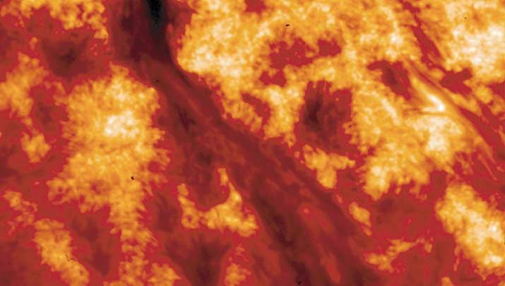
Figure 6. Detail from the previous image. The image size is 158 × 88 arc sec. A large filament
surrounded by active region network is clearly seen. An active filament channel is visible at the
upper right corner of the image.
the bright filamentary structures embedded in the large, dark Hα filament (Fig-
ure 3). They are so numerous that the filament is mostly emitting in Lα rather
than absorbing, as is usually seen in Hα observations of filaments. The correlation
of these chromospheric structures with photospheric magnetograms and coronal
structures imaged with the Michelson Doppler Imager, the Transition Region and
Coronal Explorer and the Extreme ultraviolet Imaging Telescope experiments is
being explored. The results will be published in a separate paper.
5. Conclusions
The 0.33 arc sec spatial resolution of VAULT is on the order of the predicted scale
lengths of dissipative processes in the solar atmosphere, the mean free path of Lα
photons, the spatial scales associated with the underlying photospheric granulation,
and predicted diameters of magnetic flux tubes. The VAULT images of the upper
chromosphere and transition region, obtained at unprecedented spatial resolution in
the ultraviolet, reveal a highly dynamic chromosphere comprised of interacting fine
scale loops and bright knots. The active region plage is comprised of interacting,
fine scale loop structures undergoing continuous evolution. The rearrangement of
these structures is consistent with an explanation of footprint driven magnetic re-
connection or possibly sporadic heating/injection of material. The filament channel
contains a network of light bridge like structures. The observed structures have
finer resolution than available magnetograph and coronal images from present or-VAULT IN-FLIGHT PERFORMANCE
Figure 7. The figure shows successive magnified images of an area close to a filament channel. The area inside each box is magnified by a factor of four in
the subsequent image. The original VAULT data was binned to 0.3 arc sec pixels in the first image. The last image demonstrates that fine scale structures of
< 0.5 arc sec are readily visible in the VAULT data. The axes are labeled in arc sec.
7172 C. M. KORENDYKE ET AL.
biting instrumentation. These images are the highest resolution images of the solar
atmosphere obtained from a space instrument to date. The next flight of the VAULT
instrument is scheduled for the spring of 2001. We plan an observing sequence
similar to the one in the first flight. For this flight, we will increase the instrument
throughput by using improved versions of the current Lyα filter and CCD camera.
Several other upgrades are also in progress. With these improvements, we hope
to obtain images with improved SNR and even higher resolution than the ones
presented herein.
Acknowledgements
The exemplary achievements presented in this paper are the product of many years
of development at the Naval Research Laboratory Solar Physics Branch and the
NASA sounding rocket program. The VAULT instrument borrows heavily from
the High Resolution Telescope and Spectrograph. We gratefully acknowledge the
contribution of J.-D. F. Bartoe to the HRTS program. Without his work, the HRTS
instrument would never have been built. We also gratefully acknowledge the con-
tribution of Dr G. E. Brueckner, former head of the Solar Physics Branch, who
passed away in 1998. Without his steady support and scientific guidance, neither
VAULT nor HRTS would have been built. He pioneered the field of high-resolution
solar spectroscopy. The VAULT instrument was designed, fabricated, assembled
and tested by a highly experienced Naval Research Laboratory technical team. We
would like to especially acknowledge the important contributions of the following
individuals. R. Feldman was principally responsible for the flight and ground sup-
port equipment software. D. N. Lilley is responsible for the mechanical design of
the payload. R. W. Moye is the lead mechanical technician responsible for detailed
design of the subassemblies and also responsible for the assembly and testing of the
instrument. D. E. Roberts is responsible for the pinouts, harnesses, wiring as well
as electrical testing of the payload. E. L. Shepler packaged the PC-104 computer
for flight and designed the instrument vacuum port. J. K. Smith was responsible
for the design and test of the mechanism driver cards and associated GSE. His
support in the field was vital to the success of the program. T. R. Spears was
responsible for potting the optics and the initial optical testing and demonstration
of the spectroheliograph. R. S. Waymire was responsible for the laboratory test
facilities. J. Moser was responsible for providing the VAULT power converters.
W. E. Brown of Apogee Instruments was responsible for the camera and associated
drive electronics. His personal involvement and support made this program possi-
ble within the constraints of a sounding rocket program budget. J. Shea of Perdix
Corporation was responsible for the FIFO card. Optical Systems Technology man-
ufactured the telescope optics. Hyperfine fabricated the gratings. We would like to
acknowledge the assistance of the Laboratory for Physical Sciences, College Park,
MD, who supported Dr Moulton during the field operations. Finally, we would likeVAULT IN-FLIGHT PERFORMANCE 73
to acknowledge the efforts of the Wallops Flight Facility and White Sands Missile
Range sounding rocket support team. Without their efforts, this launch would not
be possible. We would like to particularly acknowledge the following individuals:
Frank Lau and Jan Neville did a superb job managing the launch of the VAULT
payload. Frank Lau managed the development of the Mark 7 digital SPARCS at-
titude control system. We would like to acknowledge the SPARCS team for their
superb efforts in the support of our launch. Jesus and Carlos Martinez developed
and operated the Mark 7 SPARCS. Richard Garcia, Shelby Elborn and Kenneth
Starr developed the VAULT telemetry section. The support from the White Sands
Missile Range and Wallops Flight Facility NASROC personnel was of the highest
caliber. The individuals involved carried out their tasks with high degree of com-
petence and care. The VAULT instrument development work has been supported
by the ONR task area SP033-02-43 and by NASA defense procurement request
S-84002F.
References
Bartoe, J.-D. F. and Brueckner, G. E.: 1975, J. Opt. Soc. Am. 65, 13.
Brueckner, G. E. and Bartoe, J.-D. F.: 1983, Astrophys. J. 272, 329.
Dere, K. P.: 1989, Astrophys. J. 340, 599.
Dere, K. P., Bartoe, J.-D. F., Brueckner, G. E., Cook, J. W., and Socker, D. G.: 1987, Science 238,
1267.
Dere, K. P., Bartoe, J.-D. F., Brueckner, G. E., Ewing, J. A., and Lund, P. A.: 1991, J. Geophys. Res.
96, 9399.
Einaudi, G., Velli, M., Politano, H., and Pouget, A.: 1996, Astrophys. J. 457, L113.
Hendrix, D. L. and Van Hoven, G.: 1996, Astrophys. J. 467, 887.
Rabin, D. and Moore, R.: 1984, Astrophys. J. 285, 359.
Van Ballegooijen, A. A.: 1986, Astrophys. J. 311, 1001.You can also read


