How to calculate embodied carbon - IStructE
←
→
Page content transcription
If your browser does not render page correctly, please read the page content below

How to calculate
embodied carbon
How to calculate embodied carbon

ii
     | The Institution of Structural Engineers
       How to calculate embodied carbon

Authors
O P Gibbons               MEng (Arup)
J J Orr                   MEng(Hons) PhD CEng MIStructE FHEA (University of Cambridge)

Reviewers
W Arnold                  MEng(Hons) CEng MIStructE (Arup + The Institution of Structural Engineers)
S Boote                   BEng(Hons) CEng MIStructE AMICE (Webb Yates Engineers)
R Boyd                    MEng CEng MICE (Arup)
J Burridge                MA CEng MICE MIStructE (MPA The Concrete Centre)
T Ellis                   BSc MSc CEnv MIEnvSc (Arup)
M Farnetani               MArch MSc ARB BREEAM-AP (Hilson Moran)
B Gholam                  CEng MIStructE (Price & Myers)
A Girao-Coelho            PhD MSc CEng (British Constructional Steelwork Association)
W Hawkins                 MEng PhD (University of Bath)
T Ibell                   CEng FREng PhD FIStructE FICE FHEA (University of Bath)
Q Li                      PhD MArch BArch (Cundall)
A Lynes                   MA MEng(Hons)(Cantab) CEng MIStructE (Webb Yates Engineers)
E Marsh                   MEng GMICE (University of Cambridge)
M Moynihan                CEng MIStructE (Laing O’Rourke)
A Papakosta               MSc MEng (SCS Railways)
I Poole                   MEng (Mott MacDonald)
J Prew                    BSc(Hons) CEng MIStructE MICE MAPM (Hampshire County Council)
J Ratcliffe               MEng CEng FIStructE PE (scale consulting ltd)
W Rogers-Tizard           CEng MIStructE (Price & Myers)
T Ronalds                 MEng CEng MIstructE (Eckersley O’Callaghan)
M Sansom                  BEng PhD CEnv MICE (Steel Construction Institute)
K Symons                  MEng MA MIStructE MICE CEng CPEng CMEngNZ IntPE(NZ) (New Zealand Government)
N Watson                  EngD CEng MICE (Buro Happold)
F Yang                    BS MEng SE(CA) (Arup)

Publishing
L Baldwin                 BA(Hons) DipPub (The Institution of Structural Engineers)
L Woodward                BSc PGCE (Editorial & Academic Services)

Acknowledgements
Permission to reproduce the following has been obtained, courtesy of these individuals/organisations:
Front cover image: leungchopan (Adobe Stock)
Data used in Figure 2.4: © OneClick LCA
Published by The Institution of Structural Engineers
International HQ, 47–58 Bastwick Street, London EC1V 3PS, United Kingdom
T: +44(0)20 7235 4535
E: mail@istructe.org
W: www.istructe.org
First published (version 1.0) August 2020
978-1-906335-46-5 (print)
978-1-906335-47-2 (pdf )
© 2020 The Institution of Structural Engineers
The Institution of Structural Engineers and the members who served on the Task Group which produced this Guide have endeavoured to ensure the
accuracy of its contents. However, the guidance and recommendations given should always be reviewed by those using the Guide in light of the facts
of their particular case and any specialist advice. No liability for negligence or otherwise in relation to this Guide and its contents is accepted by the
Institution, its servants or agents. Any person using this Guide should pay particular attention to the provisions of this Condition.

No part of this publication may be reproduced or stored in a retrieval system without prior permission of The Institution of Structural Engineers,
who may be contacted at: 47–58 Bastwick Street, London EC1V 3PS, United Kingdom.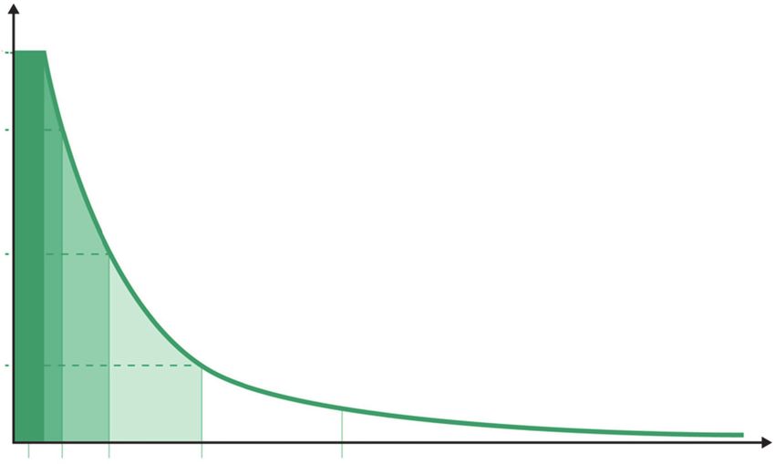
The Institution of Structural Engineers
                                                                   How to calculate embodied carbon       | iii

Contents
Foreword                                                                                                  iv
Purpose, principles and impact                                                                             v
1     Introduction to carbon calculations                                                                   1
1.1   Life cycle stages and modules                                                                         1
1.2   Terminology                                                                                           2
2     Calculating embodied carbon                                                                           4
2.1   Minimum scope of calculation                                                                          5
      2.1.1      Minimum scope: life cycle stages and modules                                               5
      2.1.2      Minimum scope: building elements                                                           5
2.2   Inputs                                                                                                7
      2.2.1      Material quantities                                                                        8
      2.2.2      Inputs for A1–A5 calculation                                                               9
      2.2.3      Module A4 carbon factors                                                                 18
      2.2.4      Module A5 carbon factors                                                                 20
      2.2.5      Additional inputs for A–C calculations                                                   23
      2.2.6      Additional inputs for A–D calculations                                                   26
2.3   Process                                                                                             29
      2.3.1      Calculation                                                                              29
      2.3.2      Normalising results                                                                      32
      2.3.3      Sense check                                                                              33
      2.3.4      Uncertainty                                                                              33
      2.3.5      Communicate and discuss embodied carbon                                                  34
      2.3.6      Calculation tools                                                                        37
      2.3.7      Reducing embodied carbon                                                                 37
2.4   Outputs                                                                                             39
      2.4.1      Reporting publicly                                                                       39
      2.4.2      As-built calculation                                                                     40
      2.4.3      Share case studies                                                                       40
3     Conclusions                                                                                         41
      Appendix: Carbon factor databases                                                                   42
      References                                                                                          44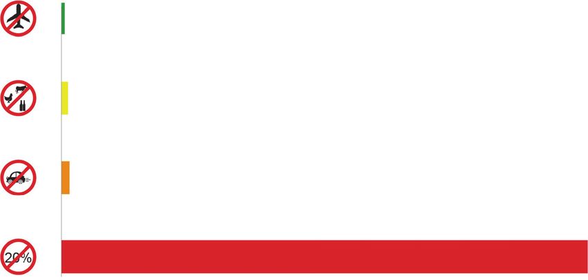
iv
     | The Institution of Structural Engineers
       How to calculate embodied carbon

Foreword
This document supports legislation by UK Parliament to achieve net zero carbon emissions by 2050 and forms a
part of the response of The Institution of Structural Engineers to implement the necessary changes in the profession
to respond to the climate emergency.

Naturally, the materials that structural engineers specify must be used efficiently to create structures that are safe and
durable. But it is now abundantly clear that structural engineers need to reduce the harm that manufacture and
disposal of these materials cause our planet’s ecosystem, which accounts for 11% of global greenhouse gas
emissions. Hence, we must reduce the embodied carbon of the structures we design.

Structural engineers need an agreed set of principles for the measurement of embodied carbon to be able to make
meaningful comparisons and carbon reductions across the construction industry. This will allow us to set agreed
carbon target levels for structures and track the level of reduction in embodied carbon, to ensure we achieve
net zero carbon by 2050.

Being able to measure and compare embodied carbon of structures is only one step in the quest for the
decarbonisation of the construction industry. Yet it is an important step because it allows us to place ‘embodied
carbon’ alongside ‘embodied costs’ in the design of structures — managing carbon footprint through material
selection and specification, material reuse, lean design and waste reduction. An ability to quantify the benefits of low
carbon design to the client and society and ensure we meet targeted reductions is crucial for the future.

This guidance will help inform structural engineers, and the professionals with whom they collaborate, about ways
they can move towards net zero carbon design. The need is becoming increasingly urgent and the consequences of
failure are increasingly alarming.

Dr Mike J Cook
IStructE Climate Emergency Task Group Chair
The Institution of Structural Engineers
How to calculate embodied carbon |v
Purpose, principles and impact
Purpose
This guide provides a common set of embodied carbon calculation principles for the structural engineering
community to follow. The imperative to achieve net zero carbon by 2050 must change the way we practice —
and calculating carbon is a key part of this.
Calculating embodied carbon in the same rigorous way across all designs will allow meaningful comparisons to be
made between structural schemes, developing our understanding of embodied carbon as well as how we can most
effectively reach net zero carbon. This guidance is equally applicable to infrastructure and building projects.
The calculation of embodied carbon must become a key part of every design process. Such efforts support our
immediate need to reduce resource demand and increase reuse and recycling to enable a circular economy.
This guide builds on the IStructE’s portfolio of guidance documents, FAQs and articles related to embodied carbon1,
a topic that has long been on the agenda of some pioneering members of the IStructE community. It supports the
sustainability related core tasks in The Structural Plan of Work 2020 2.
References to embodied carbon data and guidance in this document are UK-focused. Where the authors are aware
of such information from other countries, it is referenced in the Appendix. This document is aligned with BS EN 159783,
BS EN 158044 and RICS Professional Statement Whole life carbon assessment for the built environment 5.
Principles
We must:
• Achieve net zero carbon6 before 2050
• Calculate embodied carbon† on all projects
• Recognise carbon as one component of sustainability
• Evaluate design decisions against their carbon impact
• Communicate carbon insights to the project team
• Advocate and engage the project team to find ways to reduce carbon impacts
• Report module-based†† carbon data to an open source database
⇒ Suggestions, hints, common pitfalls and tips are captured in red boxes.
Key principles are contained within green boxes.
Grey boxes highlight the end of a process or calculation stage.
†
As a minimum, we must calculate cradle to practical completion carbon emissions (life cycle Modules A1–A5, as explained in Section 1.1 and
Figure 2.2), also known as ‘upfront carbon’.
††
Stage D must always be reported separately to Stages A–C.vi
| The Institution of Structural Engineers
How to calculate embodied carbon
Impact
It is important to realise the scale of impact that our professional activities have on the climate. Buildings and
construction presently account for around 40% of energy-related CO2 emissions. Deep changes across the design,
construction, use and reuse of buildings and infrastructure are required if we are to have any chance of providing a
sustainable environment for the 9.7bn people, including 6.5bn city dwellers, who will share our planet in 2050.
Figure 0.1 contextualises the scale of opportunity the average structural engineer has to reduce carbon emissions in
comparison to the impact the average citizen may have by making a significant environmentally-conscious change to
their personal lives.
Figure 0.1: Contextualising potential impact of structural engineers†
Cut one return flight to
New York in economy Save 1,000kgCO2e
Cut meat, dairy and beer Save 2,000kgCO2e per year
from your diet
Stop driving Save 3,000kgCO2e per year
your car
20% structural embodied
carbon reduction achieved Save 200,000kgCO2e per year
Analysis of recently constructed buildings has demonstrated that material inefficiencies in the order of 50% are
common7. Overdesign of buildings and infrastructure must also be tackled to reduce material demand and to help
meet carbon targets.
One route to zero carbon structural design is through the reuse and life extension of existing buildings and their
component parts. Doing nothing while meeting your client’s brief requires much thought and engineering analysis but
is essential if we are to dramatically cut carbon emissions. You should resist demolition wherever you can and ensure
reuse in some form as a key part of every design you create. End of life discussions are thus an integral part of
achieving a circular economy.
†
20% structural embodied carbon reduction achieved is based on the assumption of a structural engineer being responsible for (on average)
5,000m2 development per year, at an average A1–A5 emissions of 200kgCO2e/m2 (substructure and superstructure) and achieving embodied
carbon reductions of 20% (i.e. reduction of 40kgCO2e/m2).
∗
Values approximated. Return flight to New York including radiative forcing calculated using https://carbon.tips/calc. Impact of diet is an
approximate value assuming a saving each week of 1–2 portions each of beef, chicken, lamb and fish, 7 × 200ml portions of dairy milk and 7 pints
of beer, calculated using https://carbon.tips/diet. Driving emissions calculated assuming 10,000 miles per year in an average petrol car, using
https://carbon.tips/calc.The Institution of Structural Engineers
How to calculate embodied carbon |1
1 Introduction to carbon
calculations
1.1 Life cycle stages and modules
To help describe the environmental impact of an asset, its life cycle is split into stages and modules as defined by
BS EN 158044 (Figure 1.1)†. The environmental impact this guidance refers to is carbon dioxide equivalent emissions
(kgCO2e), also known as global warming potential (GWP).
An example split of emissions from Modules A1–C4 is shown at the base of Fig. 1.1, using example data from the
LETI Embodied Carbon Primer 9 across all building elements for a medium scale residential building. This highlights
the importance of Modules A1–A3 to Embodied Carbon Over the Life Cycle (Section 1.2).
Remember that efforts to calculate, report and reduce embodied carbon should be taken in conjunction with bigger
picture discussions about the whole life performance of built assets along with emissions from land use change.
Embodied carbon is just one piece of the sustainability puzzle.
Figure 1.1: BS EN 159783 Life cycle stages. Example split of emissions from Modules A1–C4 shown at bottom,
using example data across all building elements for a medium-scale residential building. Operational carbon
modules outlined in red
†
Note that infrastructure projects should review PAS 20808, which uses a similar structure but with slightly different terminology, and the
addition of a ‘pre-construction stage’ that consists of Module A0.2
| The Institution of Structural Engineers
How to calculate embodied carbon
There are four life cycle stages:
• Product stage (also known as ‘cradle to gate’). Modules A1–A3. kgCO2e released during extraction, processing,
manufacture (including prefabrication of components or elements) and transportation of materials between these
processes, until the product leaves the factory gates to be taken to site. Note that recycled content of a product
affects the kgCO2e released in modules A1–A3. Whether it is recycled after its end of life or not, does not affect
the A1–A3 impact of the project being considered — this is taken into account in Module D
• Construction process stage. Modules A4 and A5. kgCO2e released during transport of materials/products to
site, energy usage due to activities on site (site huts, machinery use etc.) and the kgCO2e associated with the
production, transportation and end of life processing of materials wasted on site
• Use stage. Modules B1–B7. kgCO2e released due to use, maintenance, repair, replacement, refurbishment and
operational energy and water use while the building is in use. Module B4 (replacement) is often the focus of the
use stage when embodied carbon is being considered
• End of life stage. Modules C1–C4. kgCO2e released during decommissioning, stripping out, demolition,
deconstruction, transportation of materials away from the site, waste processing and disposal of materials
There is one additional stage beyond the life cycle of the asset that is intended to provide a broader view of its
environmental impacts:
• Benefits and loads beyond the system boundary. Module D. This estimates any net kgCO2e benefits or loads
beyond the project’s life cycle associated with:
○ recycling of materials, e.g. use of scrap steel (rather than virgin iron) in steelmaking on future projects
○ energy recovered from materials, e.g. energy generated by incinerating timber products
○ full reuse of materials/products
when compared to the standard practice/standard product it would be replacing
1.2 Terminology
This section presents terminology commonly used in industry, and thus aligns with the terminology used throughout
this guide. Note that the terms are not always used consistently across all built environment publications.
Building component: A prefabricated assembly of materials that form a product with a specific function, e.g. a
precast concrete floor unit, a facade unit.
Building element: A major physical part of a building that fulfils a specific function, or functions, irrespective of its
design, specification or construction, e.g. floors, frame, external walls8.
Carbon factor: Normally measured in kgCO2e per unit of product e.g. kgCO2e/kg.
CEN/TC 350 Sustainability of construction works: The technical committee responsible for the development of
standardised methods for the assessment of sustainability aspects of new and existing construction works,
and for standards for the Environmental Product Declarations (EPDs) of construction products (Figure 1.2).
kgCO2e: Carbon dioxide equivalent emissions, or ‘carbon’ for short. This can also be referred to as ‘global warming
potential’ (GWP).
Environmental Product Declaration (EPD): An independently verified and registered document that communicates
transparent and comparable information about the life cycle environmental impact of products.
Embodied carbon (kgCO2e): Carbon emissions associated with:
• extraction and manufacturing of materials and products
• in-use maintenance and replacement
• end of life demolition, disassembly and disposal
including transportation relating to all three9.The Institution of Structural Engineers
How to calculate embodied carbon |3
Embodied carbon to practical completion (kgCO2e): Modules A1–A5. This is the carbon emissions associated
with the extraction and processing of materials, the energy and water consumption used by the factory in producing
products, transporting materials to site, materials wasted on site and energy used due to construction activity
(also referred to as ‘upfront embodied carbon’)10.
Embodied carbon over the life cycle (kgCO2e): Carbon emissions associated with Modules A1–A5, B1–B5 and
C1–C4.
Net zero carbon: When the amount of carbon emissions associated with a building’s embodied and operational
impacts over the life of the building, including its disposal, are zero or negative11. Since offsetting carbon emissions
must only be a last resort, and given that there are no negative emissions options, we advise that you should view
the carbon target as an absolute one: zero carbon means zero emissions.
Operational carbon (kgCO2e): The carbon dioxide associated with the in-use operation of the building, Modules B6
and B7. This usually includes carbon emissions associated with heating, hot water, cooling, ventilation and lighting
systems, as well as those associated with cooking, equipment and lifts, i.e. both regulated and unregulated energy
uses10.
Regulated energy: Energy consumed that is within the scope of building regulations.
Unregulated energy: Energy consumed that is outside the scope of building regulations.
Whole life carbon (kgCO2e): Carbon emissions associated with Stages A–C and D, with Stage D reported
separately. This may also be referred to as ‘cradle to cradle’.
Figure 1.2: Relationship between selected documents developed by CEN/TC 350
Sustainability of construction works
CEN/TC 350 https://carbon.tips/tc350
Framework level
Building level
BS EN 15643-1 (2010)
Sustainability Assessment of Buildings – Product level
BS EN 15978 (2011)
General Framework
Assessment of environmental performance of
BS EN 15804 (2012) +A2 (2019)
buildings. Calculation method
BS EN 15643-2 (2011) Environmental product declarations – Core rules
Assessment of Buildings. Framework for the for the product category of construction products
PD CEN/TR 17005 (2016)
assessment of environmental performance
Additional environmental impact categories and
PD CEN/TR 16970 (2016)
indicators – Background information and
possibilities – Evaluation of the possibility of Guidance for the implementation of EN 15804
adding environmental impact categories and
related indicators and calculation methods for BS EN 15942 (2011)
the assessment of the environmental Environmental product declarations –
performance of buildings Communication format business-to-business
PD CEN/TR 15941 (2010)
Environmental product declarations –
Methodology for selection and use of generic data4
| The Institution of Structural Engineers
How to calculate embodied carbon
2 Calculating embodied carbon
The fundamental principle of an embodied carbon calculation is to multiply the quantity of each material
by a carbon factor for the life cycle modules being considered†:
material quantity (kg) × carbon factor (kgCO2e/kg) = embodied carbon (kgCO2e)
Use embodied carbon as a key design metric and communicate findings to your design team members whenever
there is a significant design decision to be made and at project milestones.
The most important time to calculate embodied carbon is in the early design stages. The earlier the better.
It is crucial to have time and scope to make changes in light of your embodied carbon assessment.
At the end of each project, report embodied carbon data to an open source database (Section 2.4.1), and submit
lessons learned to The Structural Engineer magazine12. Figure 2.1 outlines how such calculations can be integrated
into any stage of a typical project. Items in green boxes are addressed in this guidance.
Figure 2.1: Calculating embodied carbon process overview (1)
Start
Inputs Process Outputs
Consider the brief and undertake an option study
(e.g. do nothing, vary materials, change grids, challenge loadings, minimise intervention
in existing structures, reuse existing materials, create direct load paths)
For each option
Select embodied Calculate embodied carbon Report final design to
Calculate
carbon data (Sections 2.3.1–2.3.3) industry database
(Sections 2.2.2–2.2.6) (Sections 2.4.1 and 2.4.2)
Identify EC hotspots
Analyse
and opportunities for reduction
Material quantities
(Section 2.2.1) Learning
Discuss with design team.
Communicate Compare to relevant benchmarks
(Section 2.3.5) Compare and contrast
design to equivalent
assets
Select benchmark
comparator projects
Select Pursue lowest carbon option(s)
Identify lessons learned
and opportunities for
future design
Improve design based on hotspot and
Reduce
opportunity analysis (Section 2.3.7)
Report findings, both
Refine inputs as design stages progress and internally and externally
Refine
material data improves (Section 2.4.3)
Feed into next project
†
The equation shown applies to materials measured in kg, where a carbon factor in kgCO2e/kg is available. Any measure of quantity may be
used, e.g. m2, m3, etc., as long as it corresponds to the units of the carbon factor, e.g. kgCO2e/m2, kgCO2e/m3, etc. If the unit of quantity
does not correspond to the unit of the carbon factor (e.g. quantity in m3, carbon factor in kgCO2e/kg), then the quantity should be adjusted,
based on the physical properties of the product, so that its units align with those of the carbon factor, or vice versa (e.g. by using the density,
kg/m3). For structural materials, carbon factors are commonly shown in kgCO2e/kg.The Institution of Structural Engineers
How to calculate embodied carbon |5
2.1 Minimum scope of calculation
As a minimum for structural elements, your calculation should include Modules A1–A5 for primary
substructure and superstructure elements. Also include Module B4 for facades if within your scope of design.
2.1.1 Minimum scope: life cycle stages and modules
This guide stipulates that the minimum life cycle scope of embodied carbon assessments for structural elements is to
include life cycle Modules A1–A5 (embodied carbon to practical completion). There are several reasons for this:
• A1–A5 emissions will be released before 2050. They are therefore the emissions we most urgently need to
understand and minimise to keep global warming within 1.5°C
• We have most certainty over A1–A5 emissions data
• Typically, the majority of the embodied carbon of structures is associated with Modules A1–A5, therefore this
should be the focus of our carbon reduction efforts
However, best practice is to consider whole life embodied carbon (Stages A–C plus D), so that we not only minimise
embodied carbon emissions today but also consider the future emissions impacts of using the asset, durability,
longevity, end of life scenarios, reusability and recyclability. This will ensure that future emissions and resource
consumption are also kept to a minimum. If Stages A–C are calculated, it is important to report A1–A5 results
alongside A–C results.
Be aware that design for minimum upfront carbon can run counter to discussions on future flexibility. Where design
teams are advocating longer spans, or higher floor loading, use your carbon calculations to quantify the
environmental impact of such choices. You will need to weigh up the certainty of an increase in carbon emissions
today with the probability of a future change in use, based on the local context. Changes in use may be achieved by
means other than building-in extra upfront capacity; for example, by being flexible about what an office space or
residential space really needs, or by appropriately designed strengthening works applied in the future. The same
discussions should occur when demountable or reusable component design is discussed. A key challenge today is
the reuse and life extension of existing buildings.
Note that the RICS Professional Statement Whole life carbon assessment for the built environment 5 states that the
minimum scope of assessment for a whole building carbon assessment is Modules A1–A5 + B4 (for facades) + B6.
This guidance aligns with that document, as Modules B4 and B6 rarely need to be considered in a structural design.
2.1.2 Minimum scope: building elements
This guide stipulates that the minimum building element scope of embodied carbon assessments for structural
elements is to include primary substructure and superstructure. You should also calculate the embodied carbon
associated with all other elements within your scope of works.
For buildings, the Building Cost Information Service’s (BCIS) Elemental Standard Form of Cost Analysis (SFCA)13
summarised in Table 3 of RICS’ Whole life carbon assessment for the built environment, are used to categorise
elements included in a carbon assessment. For a structural engineer, the building element categories most likely to
be included in an embodied carbon calculation are given in Table 2.1 of this guidance, with the minimum scope
highlighted in green.
⇒ Table 2.1 (right hand column) suggests a way to categorise structural elements included in your calculation
to allow better insights into where the embodied carbon lies, and thus how to minimise it. If you do
categorise elements in a different way to the BCIS SFCA categories, show how they relate in your design
reports, for transparency with other disciplines.6
| The Institution of Structural Engineers
How to calculate embodied carbon
Table 2.1: BCIS SFCA building element categorisations relating to structural elements, mapped against a
possible way of breaking down structural elements for carbon analysis. Minimum scope of calculation
highlighted in green
Building part/element Building element (BCIS SFCA) Possible breakdown of structural
group (BCIS SFCA) elements for carbon analysis
0 Facilitating works 0.2 Major demolition works
0.3 Temporary support to adjacent
structures
0.4 Specialist ground works
1 Substructure 1.1 Substructure Foundations (including pile caps)
Ground bearing slab
Basement retaining walls
2 Superstructure 2.1 Frame Columns
Braces
2.2 Upper floors Beams
Slabs (incl. permanent formwork)
2.3 Roof Roof beams
Roof slab
2.4 Stairs and ramps Stairs and ramps
2.5 External walls Structural external walls
2.7 Internal walls and partitions Structural internal walls
6 Prefabricated buildings 6.1 Prefabricated buildings and building
and building units units
7 Work to existing building 7.1 Minor demolition and alteration works
Note: Complete category list can be found in Table 3 of RICS’ Whole life carbon assessment for the built environment.
For the embodied carbon of structural schemes to be meaningfully compared, you should also consider whether any
other building elements are dictated by the structural system. Liaise with the wider design team to understand what
these may be. A common example is fire protection to structural elements. A1–A3 embodied carbon factors (ECFs)
for common fire protection materials are given in Table 2.3 so that they can be included in your assessment if
necessary.
Considering whole life and whole building carbon emissions requires collaboration across the project team, which this
guide strongly advocates. Although structural engineers need to be fluent in the embodied carbon of structures to
contribute to achieving a zero-emissions built environment, we must not lose sight of how our designs affect
emissions associated with the work of other disciplines.
⇒ Coordinate assessments across teams to ensure you know who is responsible for which building elements.
Your scope of calculation should at least reflect what you are responsible for designing and this should be
clearly reported.The Institution of Structural Engineers
How to calculate embodied carbon |7
2.2 Inputs
The inputs described in Table 2.2 need to be obtained to calculate embodied carbon for the respective life cycle
modules.
Table 2.2: Inputs required for embodied carbon assessments
Input required Life cycle Section
module reference
Inputs required for A1–A5 Material or product quantities All stages Section 2.2.1
(to practical completion)
A1–A3 carbon factors A1–A3 Section 2.2.2.1
Distance, mode emissions intensity of A4 Section 2.2.3
transportation of materials to site
On site material wastage rates A5 Section 2.2.4.1
Site activities emissions A5 Section 2.2.4
Additional inputs for A–C Building element replacement cycle B4 Section 2.2.5.1.1
(over the life cycle)
Asset lifespan (reference study period) B4 Section 2.2.5.1.1
Demolition and deconstruction emissions C1 Section 2.2.5.2.1
Distance and mode emissions intensity of C2 Section 2.2.5.2.2
transportation of materials away from site
End of life scenarios C3 and C4 Section 2.2.5.2.3
Additional inputs for A–D End of life scenarios D Section 2.2.6
(whole life carbon)
Difference between A1–A3 carbon factors of D Section 2.2.6
the secondary product and the substituted
product
Sections 2.2.1–2.2.6 describe how to obtain these inputs (with references to relevant sources of information), and
how to create a carbon factor for each of the life cycle modules within the scope of your embodied carbon
assessment. Note that this guidance focuses on UK references. However, the same principles apply to embodied
carbon calculations globally.
For Stage B, we focus on B4 (replacement) as:
• Module B1 (use) is generally insignificant for structural materials
• Very little data exists for Modules B2 (maintenance) and B3 (repair)
• Module B5 (refurbishment) refers to planned changes in use defined at the start of the project
• Modules B6 and B7 address operational carbon and are outside the scope of this guide
Section 2.2.5.1 contains more detail on Stage B modules.8
| The Institution of Structural Engineers
How to calculate embodied carbon
2.2.1 Material quantities
Figure 2.2: Calculating embodied carbon process overview (2)
Start
Inputs Process Outputs
Consider the brief and undertake an option study
(e.g. do nothing, vary materials, change grids, challenge loadings, minimise intervention
in existing structures, reuse existing materials, create direct load paths)
For each option
Select embodied Calculate embodied carbon Report final design to
Calculate
carbon data (Sections 2.3.1–2.3.3) industry database
(Sections 2.2.2–2.2.6) (Sections 2.4.1 and 2.4.2)
Identify EC hotspots
Analyse
and opportunities for reduction
Material quantities
(Section 2.2.1) Learning
Discuss with design team.
Communicate Compare to relevant benchmarks
(Section 2.3.5) Compare and contrast
design to equivalent
assets
Select benchmark
comparator projects
Select Pursue lowest carbon option(s)
Identify lessons learned
and opportunities for
future design
Improve design based on hotspot and
Reduce
opportunity analysis (Section 2.3.7)
Report findings, both
Refine inputs as design stages progress and internally and externally
Refine
material data improves (Section 2.4.3)
Feed into next project
DO NOT be deterred from calculating embodied carbon at early design stages because of uncertainty in
material quantities.
Material quantities† can be calculated in a number of different ways, depending on the stage of design and the tools
available, including:
• Manual calculations
• BIM models
• Structural analysis models
• Scheming manuals (e.g. Structural Engineer’s Pocket Book: Eurocodes 14)
• Preliminary calculations on representative/repeated structural elements
• Previous project experience
• A quantity surveyor’s cost plan††
Uncertainty in material quantities will decrease over the course of a project. Update your calculations regularly to
reflect this.
†
The carbon data you use may dictate how you report your quantities, whether it is in kg, m3 or m2. Use material properties to toggle between
these different measures as needed.
††
Obtaining quantities from the quantity surveyor’s (QS) cost plan is the least favourable option in terms of being able to feed embodied carbon
information into the design process, as there is a time lag between designing and receiving this information to calculate embodied carbon.The Institution of Structural Engineers
How to calculate embodied carbon |9
⇒ Be aware of common elements that are often only partially modelled but need to be included in the
carbon count: paint and intumescent coverings, piles and footings, concrete blinding, connections (for steel
frames a % allowance is usually made), bolts, studs, permanent decking or formwork, rebar laps, etc.
Check the specification against your material lists.
⇒ Use quantities collected during construction to create an as-built carbon assessment.
Now you have a list of materials and their quantities (usually in kg or m3).
2.2.2 Inputs for A1–A5 calculation
2.2.2.1 Stage A1–A3 carbon factors
Modules A1, A2 and A3 are very likely to constitute the majority of structural embodied carbon over the
life cycle of a project.
Figure 2.3: Calculating embodied carbon process overview (3)
Start
Inputs Process Outputs
Consider the brief and undertake an option study
(e.g. do nothing, vary materials, change grids, challenge loadings, minimise intervention
in existing structures, reuse existing materials, create direct load paths)
For each option
Select embodied Calculate embodied carbon Report final design to
Calculate
carbon data (Sections 2.3.1–2.3.3) industry database
(Sections 2.2.2–2.2.6) (Sections 2.4.1 and 2.4.2)
Identify EC hotspots
Analyse
and opportunities for reduction
Material quantities
(Section 2.2.1) Learning
Discuss with design team.
Communicate Compare to relevant benchmarks
(Section 2.3.5) Compare and contrast
design to equivalent
assets
Select benchmark
comparator projects
Select Pursue lowest carbon option(s)
Identify lessons learned
and opportunities for
future design
Improve design based on hotspot and
Reduce
opportunity analysis (Section 2.3.7)
Report findings, both
Refine inputs as design stages progress and internally and externally
Refine
material data improves (Section 2.4.3)
Feed into next project10
| The Institution of Structural Engineers
How to calculate embodied carbon
The A1–A3 carbon factor† depends on:
• Location where project will be constructed (when using average values typically provided by region or country)
• Location where the products/components are to be manufactured (when supply chain is better understood and
component origin is known)
• The material specification
The range in embodied carbon can be large. For example, the A1–A3 carbon factor for UK-produced reinforcement
bar could be as low as 0.684kgCO2e/kg, while a UAE-produced bar with no recycled content could be closer to
2.13kgCO2e/kg. To get the most accurate carbon assessment and therefore make the best decisions, at the start of
a project, ask your client or a local contractor how they normally source their materials. If you are unable to
determine this, use the default values in Table 2.3.
There are a number of different sources of material carbon factors. Some express industry averages for a supplier,
a group of suppliers or for a country. Others express the embodied carbon of a specific product.
⇒ Choose a factor that best reflects your understanding at the time of calculation, for the source and
specification of the material. In the early design stages, this usually means selecting regional or industry
average carbon factor data, such as those outlined in Table 2.3. Flag your uncertainty, be transparent about
any assumptions made and revisit your choice of A1–A3 carbon factors at later design stages.
DO NOT be deterred from calculating embodied carbon at early design stages because of uncertainty of
carbon factors.
The Inventory of Carbon and Energy 15, commonly known as ‘ICE’, is an open source material carbon factor
database. It contains UK-specific data as well as European and global averages, based on EPDs, some of which is
referenced in Table 2.3. Similar databases from other countries are listed in the Appendix.
2.2.2.1.1 Unknown material or product specifications
Use default material specifications unless you wish to commit to driving a particular material specification through the
design process, and/or until you know more about where/how materials will be sourced.
Default values for commonly used structural materials (based on open source data available at the time of
publication) can be obtained from Table 2.3. Note that material ECFs are likely to change over time as production
processes are made more efficient and the electricity grid decarbonises. If you cannot find materials that will be used
on your project in Table 2.3, the ICE database or Section 2.2.2.1.2 of this guidance contains a list of EPD sources to
look through.
⇒ The energy supply mix in different geographical areas can impact the carbon emissions associated with
production of a product. Until product specific EPDs have been chosen it is sensible to use national,
regional or international average data points.
⇒ Table 2.3 is not exhaustive and is intended only to be used as your starting point. You should look for EPDs
that best suit your projects and use those in your calculations. Note also that the table does not cover
reclaimed materials, where A1–A3 carbon factors may be close to zero, highlighting again the need for
reuse to be a key part of your design.
†
Modules A1–A3 are normally aggregated and reported as a single carbon factor. In some circumstances, the modules may be reported
individually; check each Environmental Product Declaration (EPD) that you use, to confirm this.The Institution of Structural Engineers
How to calculate embodied carbon | 11
Table 2.3: Suggested embodied carbon factors (ECFs) of common construction materials
Material Type Specification/details A1–A3 ECF Data
(kgCO2e/kg) source
Concrete In situ: piling, Unreinforced, C30/37, UK 0.103 Ref. 16
substructure, average ready-mixed
superstructure concrete EPDa (35%
cement replacement)
Unreinforced, C32/40, 0.120 Ref. 15
25% GGBS cement
replacementb
Unreinforced, C32/40, 0.089 Ref. 15
50% GGBS cement
replacement
Unreinforced, C32/40, 0.063 Ref. 15
75% GGBS cement
replacement
Unreinforced, C40/50, 0.138 Ref. 15
25% GGBS cement
replacement
Unreinforced, C40/50, 0.102 Ref. 15
50% GGBS cement
replacement
Unreinforced, C40/50, 0.072 Ref. 15
75% GGBS cement
replacement
Generic non-structural Unreinforced, C16/20, 0.113 Ref. 15
in situ concrete 0% cement replacement
with CEM I
Mortar/screed 1: 4 cement : sand mixc 0.163 Ref. 15
with CEM I cement
1: 4 cement : sand mix 0.149 Ref. 15
with average UK
cement mixd
Precast concrete Unreinforced, C40/50 0.178 Ref. 15
with average UK
cement mix
Reinforced, 150mm 50.2 kgCO2e/m2 Ref. 17
prestressed hollow core
slab: British Precast
Flooring Federation
average EPD12
| The Institution of Structural Engineers
How to calculate embodied carbon
Table 2.3: Continued
Material Type Specification/details A1–A3 ECF Data
(kgCO2e/kg) source
Steel Reinforcement bars UK: UK CARES Sector 0.76 Ref. 18
Average EPD
Worldwide: Worldsteel 1.99 Ref. 15
LCI study data, world
average
PT strands Assume the same as reinforcement bars
Structural sections UK open sections: 2.45 Ref. 19
British Steel EPD
UK hollow sections: 2.50 Ref. 20
TATA EPD
Europe (excl. UK): 1.13 Ref. 21
Bauforumstahle average
EPD
Worldwide: Worldsteel 1.55 Ref. 15
LCI study data, world
average
Plate UK: Assume the same as ‘structural sections — UK open sections’
Europe (excl. UK): 1.13 Ref. 21
Bauforumstahl average
EPD
Worldwide: Worldsteel 2.46 Ref. 15
LCI study data
Galvanised profiled UK: TATA Comflor® EPD 2.74 Ref. 22
sheet (e.g. for decking)
Europe: PPA Europe EPD 2.36 Ref. 23
Worldwide: Worldsteel 2.76 Ref. 15
LCI study data, hot dip
galvanised steel, world
average
Blockwork Precast concrete Lightweight (AAC) blocks 0.280 Ref. 15
blocks
Dense blocks 0.093 Ref. 15
Brick Single engineering UK: BDA generic brick 0.213 Ref. 15
clay brick
Brick wall Single skin wall with 38.0kgCO2e/m2 Ref. 15
mortar 1:4 CEM I
cement :sand mix
Double skin wall with 81.9kgCO2e/m2 Ref. 15
mortar 1:4 CEM I
cement :sand mixThe Institution of Structural Engineers
How to calculate embodied carbon | 13
Table 2.3: Continued
Material Type Specification/details A1–A3 ECF Data
(kgCO2e/kg) source
Stone Granite Granite 0.70 Ref. 15
Limestone Limestone 0.09 Ref. 15
Sandstone Sandstone 0.06 Ref. 15
Timber, excl. carbon Manufactured CLT, 100% FSC/PEFC 0.437 Ref. 15
sequestrationf,g structural timber
Glulam, 100% FSC/PEFC 0.512 Ref. 15
Studwork/framing/ Softwood, 0.263 Ref. 15
flooring 100% FSC/PEFC
Formwork Plywood, 0.681 Ref. 15
100% FSC/PEFC
Aluminium Sheet European consumption 6.58 Ref. 15
(31% recycled content)
Worldwide consumption 13.0 Ref. 15
(31% recycled content)
Extruded profiles European consumption 6.83 Ref. 15
(31% recycled content)
Worldwide consumption 13.2 Ref. 15
(31% recycled content)
Glass General Generic 1.44 Ref. 15
Toughened Generic 1.67 Ref. 15
Plasterboard Partitioning/ceilings Minimum 60% recycled 0.39 Ref. 15
content
Intumescent paint For steelwork Amotherm Steel WB EPD 2.31 Ref. 24
Notes:
a
Covers 93% of production from member companies of the British Ready-Mixed Concrete Association.
b
The ICE database has a wide range of concrete mixes, including PFA (pulverised fuel ash) cements. Section 2.2.2.1.3 for
more information.
c
The ICE database has many more cement: sand ratios to choose from.
d
Taken from average UK sector cement EPD: 86.1% clinker, 0.04% GGBS, 3.4% fly ash, 4.8% gypsum, 5.1% limestone,
0.56% MACs, by weight.
e
Bauforumstahl is a group of European steel producers including ArcelorMittal, Peiner Träger and Stahlwerk Thüringen.
f
The ICE database also includes timber A1–A3 embodied carbon factors including sequestration.
g
See Section 2.2.2.1.5.
Data is current at time of publication. Check sources to ensure accuracy at time of your calculation.
Note that for the steel A1–A3 ECFs in Table 2.3, values are presented based on production location. As steel is a
continentally and globally traded product, a better ECF estimate would be based on average consumption in the
country/region your project is based. However, at the time of publication, the authors believe that such information
has not yet been published. In the absence of consumption-based data for each country/region, it is recommended
that a steel A1–A3 ECF is selected so that the production location matches the project location. For example, for a
project in the UK using steel open sections, use 2.45kgCO2e/kg19.14
| The Institution of Structural Engineers
How to calculate embodied carbon
2.2.2.1.2 Known material or product specifications
The accuracy of your carbon assessment will be greatly improved through the use of product-specific carbon data.
As your design progresses, so too should your carbon assessment certainty.
EPDs provide detailed environmental impact information for a material or product, including A1–A3 carbon factors.
Use these when you can be more certain about which countries or manufacturers your materials/products will be
sourced from. You can also use information from EPDs to help influence which products should be used to fulfil a
desired performance specification. Ask manufacturers for their EPDs or search for them online.
⇒ Make sure you always ask the manufacturer for the EPDs of their products — creating demand for good
environmental practices is a positive action.
Otherwise, you can obtain EPDs from these websites:
• Environdec: https://www.environdec.com
• Institut Bauen und Umwelt: https://ibu-epd.com/en/published-epds/
• EPD Ireland: https://www.igbc.ie/epd-search/
• BRE Green Book Live: http://www.greenbooklive.com/
• Carbon Leadership Forum: http://www.carbonleadershipforum.org/resources/
• ECO Platform: https://www.eco-platform.org/list-of-all-eco-epd.html
• Transparency Catalog: https://www.transparencycatalog.com/
• Climate Earth: https://www.climateearth.com/greenmixselector/
See the Appendix for a list of carbon factor databases from various parts of the world.
EPDs often include only Modules A1–A3, so take care if you are combining EPD data with other sources that may
include additional modules (e.g. A–C), as you will need to fill in the gaps (or at least note the limitations of such quick
calculations). If you wish to use A4 and A5 data from an EPD, always check the assumptions within these
calculations align with the project-specific circumstances and/or the advice contained within Section 2.3 of this
guidance.
BS EN 158044 now requires construction products and materials EPDs to declare Modules A1–A3, C1–C4 and D.
This will increase the availability of data for Modules C and D and can be integrated into your whole life carbon
calculations, provided all materials and products are able to be considered in the same manner.
EPDs are normally valid for five years, and their validity date will be displayed on the EPD. Make sure the data you
are using is valid.
For more information, refer to the ASBP briefing papers on EPDs25–27.
2.2.2.1.3 Concrete
The embodied carbon of concrete is most heavily influenced by the amount of Portland Cement (PC) contained
within it.
To reduce the embodied carbon of concrete, PC can be partially (or completely†) substituted by other cementitious
materials commonly known as ‘cement replacements’, the most common of which are Ground Granulated Blast
Furnace Slag (GGBS)††, Pulverised Fuel Ash (PFA)††† and limestone. It should be noted that the production of GGBS
and PFA are tied to carbon intensive industries. There are limited amounts produced globally, and efforts to
decarbonise energy supplies and steel production should result in decreased supplies in the future. Lehne and
Preston28 and Allwood et al.29 provide further insights into possible low carbon concrete technologies that may be
available in the future.
†
Products such as Cemfree and LoCem use 100% GGBS alongside an alkali-activated cementitious material (AACM).
††
Waste product from blast oxygen furnace (BOF) route of production of steel.
†††
Waste product from coal-fired power plants.The Institution of Structural Engineers
How to calculate embodied carbon | 15
Using a lower concrete strength grade will also reduce the total cementitious content requirement and thus
embodied carbon. However, this may or may not reduce the embodied carbon of a reinforced concrete section,
depending on the embodied carbon associated with any resulting increased demand for steel reinforcement and/or
concrete volume to meet performance requirements.
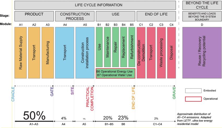
Purnell and Black30 have shown that for a given compressive strength, embodied carbon values of concrete can vary
by a factor of around three through varying the amount of PC. A similar trend is seen in Figure 2.4, where EPD data
from more than 1500 specific concrete mixes is plotted. For more insights on the variation of concrete and concrete
constituent ECF, refer to Anderson and Moncaster31. Note that it may be possible to achieve your desired
concrete strength with considerably less carbon than you imagined.
Figure 2.4: Example of possible variation in embodied carbon for concrete mixes. The concrete strength class
reported is highest end in given ranges for those mixes
0.5
0.4
Embodied carbon, A1–A3
0.3
kgCO2e/kg
0.2
0.1
0
0 10 20 30 40 50 60 70 80 90 100
Concrete strength class (MPa)
Cement type affects early age strength gain; generally, the higher the proportion of PC replacements the slower the
strength gain. It is worth noting that for this reason, currently precast concretes typically have lower limits on the
proportion of PC replacements (typically up to 25%), and so have higher embodied carbon, as concrete strength
gain affects the production rate of precast products. You should request low embodied carbon mixes for precast
products whenever you can32.
The amount of PC specified in a concrete mix is a function of application-specific requirements for strength,
durability, workability and curing speed. Your concrete mix design should be optimised to achieve the functional
requirements with minimum embodied carbon by carefully considering the mix of constituent materials. A concrete
mix is typically designed by a concrete producer from a concrete specification. It is recommended that you engage
the concrete producer when seeking low carbon concretes.
Refer to the MPA’s Specifying Sustainable Concrete 33 for guidance. Note that material quantity reduction should
always be your primary objective, followed by appropriate specification.
The ICE database provides the embodied carbon of a variety of concrete mixes of different strengths and degrees of
PC replacement, some of which are included in Table 2.3. If you cannot find a carbon factor for a concrete that
matches your concrete mix specification, you can calculate the embodied carbon of a specific mix using the freely
available Concrete Embodied Carbon Footprint Calculator 34. Alternatively, for a more accurate estimate, ask your
concrete supplier for a mix-specific embodied carbon calculation.16
| The Institution of Structural Engineers
How to calculate embodied carbon
2.2.2.1.4 Steel
The A1–A3 carbon factor of steel varies depending on its recycled content and its production method: basic oxygen
furnace (BOF) or electric arc furnace (EAF). BOF is a fossil fuel-fired (mostly coal) production process that produces
steel from high proportions of virgin iron ore compared to scrap metal (maximum 30% scrap35, and typically 13% in
the UK). EAF is a process powered by the electricity grid and can produce steel made with a very high recycled
content (up to 100%35, and typically 97% in the UK). Steel produced by EAF and with high recycled content
generally has a much lower A1–A3 carbon factor than BOF-produced steel, and this may reduce further in future as
electricity grids decarbonise.
Steel A1–A3 carbon factors also vary by steel product (e.g. hollow section, open section, plate) as the amount of
processing they go through correlates to the amount of energy used in the manufacturing process, and some products
are better suited to a specific production technique e.g. EAF or BOF. For example, hollow sections typically have a slightly
higher carbon factor than open sections (I-sections), and thin products such as steel plate are typically produced by BOF.
At early design stages, when the production method and source of steel is not known, a market average embodied
carbon factor for steel in the geographical region of the project (i.e. average carbon factor of steel consumed in that
region) is recommended. However, in the absence of regional market average data, it is recommended that a steel
A1–A3 ECF is selected so that the production location corresponds to the project location. Table 2.3 presents steel
A1–A3 ECFs based on production location, as regional market average steel carbon factors are not known to the
authors at the time of publication.
Table 2.3 quotes A1–A3 embodied carbon factors (ECFs) from the ICE database for worldwide averages, and from EPDs
for European and UK average ECFs. These A1–A3 ECFs are based on the 100:0 recycling method, which effectively only
takes the benefits from recycled scrap content in its production into account. Any benefits from recycling steel at end of
life should be accounted for in Module D (Section 2.2.6), if included in your assessment, not in Modules A1–A3. The ICE
database provides more information on different methods of accounting for recycled content and recycling rate.
2.2.2.1.5 Timber
Carbon dioxide is removed from the atmosphere as trees grow — via photosynthesis, known as ‘sequestration’. The
carbon element of this CO2 is temporarily stored within timber until it is released at end of life in the form of a greenhouse
gas (CO2 or CH4 ), for example by burning or decomposition of the timber. An example of this is illustrated in Figure 2.5.
Figure 2.5: Example of carbon stored in timber used for Harvested Wood Products (HWPs) over timea,b,c
Total sequestration
655tCO2/ha
800
Carbon stored in timber used for HWPs
700
YC12 Sitka Sprice unthinned
600
Stem
Forest Yield Tables
50% of stem carbon plus 100% Crown
ts
500
oo
of root and crown carbon released Root
tCO2/ha
+R
into atmosphere. HWP
400 w n
Total carbon released = 459tCO2 Net
ro
+C
300
em
St
200
HWP end of life,
50% of stem carbon remains stored remaining 196tCO2 released
100
in HWPs for their lifetime
(60 years in this case)
0
0 20 40 60 80 100 120
Years
Notes:
a Data obtained from Morison et al 36.
b Does not consider other greenhouse gases such as methane CH4 or nitrous oxide N2O.
Further information can be found in Morison et al 36.
c Does not include CO2 emissions due to manufacture or transport.The Institution of Structural Engineers
How to calculate embodied carbon | 17
Here we propose that carbon sequestration — part of Module A1 for timber products — should always be
considered in an embodied carbon calculation, provided that the timber originates from a sustainably managed
forest with FSC or PEFC (or equivalent) certification. However, in line with RICS guidance5, whether the
sequestration value is added to the total reported embodied carbon value depends on the scope of calculation:
• Modules A1–A5: do not include sequestration within the A1–A5 total value but report it separately alongside the
A1–A5 total (Figure 2.8)
• Modules A–C: include sequestration within the total A–C value reported (Fig. 2.8)
Emissions in Stage C account for the sequestered carbon released back into the atmosphere at the end of life of
the product. Unless reuse of the component can be guaranteed, these end of life (Modules C3 and C4) emissions
will either balance or exceed (depending on end of life scenario) the carbon sequestration in Module A1. It is
therefore extremely important to implement design measures to maximise the lifespan of timber elements to ensure
the sequestered carbon is locked up for as long as possible before being released.
The rationale behind not including carbon sequestration within the total A1–A5 value, but reporting it separately
alongside is:
• Including sequestration in the A1–A5 total would typically result in a negative value for A1–A5 embodied carbon
(i.e. showing a net extraction of carbon emissions from the atmosphere). This could allow engineers to show that
less efficient use of timber results in lower, i.e. a greater negative value of, embodied carbon. This must be
avoided to prevent unnecessary use of resources
• We should not ignore the fact that carbon sequestration happens, therefore we should show it
In the absence of product specific data, carbon sequestered† can be assumed as -1.64kgCOe per kg of timber††.
This value is derived from Equation (2.1), which is adapted from BS EN 1644937:
44 1
SCO2 = × cf × ω (2.1)
12 1+
100
Where
SCO2 = carbon sequestered, per kilogram of product, from the atmosphere (kgCO2/kg)
cf = carbon fraction of woody biomass (oven dry mass) (assume 0.50 in the absence of product specific information)
ω = moisture content (assume 12% in the absence of product specific information)
It should be noted that EPDs for timber products are now required to include the benefits of sequestration in the
A1–A3 carbon factor, under the 2019 update to BS EN 158044,†††. When reporting A1–A5 calculations, the
sequestered carbon calculated using Eqn. (2.1) should be extracted from the A1–A3 carbon factor in the EPD when
reporting A1–A5 calculations, yielding the carbon emissions due to production processes alone. In some cases,
EPDs do extract sequestration from the A1–A3 total, which would remove the need to use Eqn. (2.1). Note that the
energy used to dry timber products to a suitable moisture content can be significant.
The ICE database provides two sets of A1–A3 carbon factors for timber products, one including sequestration and
the other excluding sequestration (the latter is included in Table 2.3). End of life emissions associated with timber
products (e.g. CO2 release from incineration or CO2 and CH4 release during landfill) are reported in Stage C
(Section 2.2.5.2).
Morison et al.36 and Ramage et al.39 provide useful starting points for readers who wish to delve further into carbon
balances in forests and the use of timber in construction.
†
Carbon sequestered in a timber product is also known as ‘biogenic carbon’.
††
This assumes default values given in the RICS guidance5 of carbon factor woody biomass = 50% and moisture content = 12%.
†††
BS EN 15804:2019 follows the guidance of BS EN 16485:201438.You can also read