HUB RADIATOR PLUS HUB RADIATOR PLUS SOLAR
←
→
Page content transcription
If your browser does not render page correctly, please read the page content below
INSTALLATION MANUAL
Patented high efficiency heat pump system with direct
refrigerant / water exchange to produce domestic hot
 water and heating for medium users with or without
               solar thermal integration

      HUB RADIATOR PLUS
   HUB RADIATOR PLUS SOLAR

                                                        HUB RADIATOR PLUS / PLUS SOLAR

                           1
GENERAL INFORMATIONS
                                              HUB RADIATOR PLUS 250 - 400 SOLAR
GENERAL WARNINGS                                                                                                Incorrect installation or poor maintenance can cause damage
The instruction booklet is an integral and essential part of the                                                to people, animals or things, for which the manufacturer is not
product and must be kept by the user.                                                                           responsible.
Carefully read the warnings contained in the booklet as they                                                    In the event of a breakdown and / or malfunction of the appliance,
provide important information regarding the safety of installation,                                             contact only qualified personnel in accordance with the law.
use and maintenance.                                                                                            Any repairs to the products must be carried out only by personnel
Keep the booklet carefully for any further consultation. Installation                                           authorized by the manufacturer, using only original spare parts.
and maintenance must be carried out in compliance with current                                                  Failure to comply with the above may compromise the safety of
regulations according to the manufacturer’s instructions and by                                                 the appliance.
qualified and authorized personnel in accordance with the law.                                                  To ensure the efficiency of the appliance and for its correct
Professionally qualified personnel means those with specific                                                    operation, it is essential to have the maintenance carried out by
technical expertise in the sector of components of heating                                                      qualified personnel.
systems for civil use, production of hot water for sanitary use and                                             If the appliance is to be sold or transferred to another owner or if
maintenance.                                                                                                    you have to move and leave the appliance, always make sure that
The personnel must have the qualifications required by the law in                                               the booklet accompanies the appliance so that it can be consulted
force.                                                                                                          by the new owner and / or by the installer.

                                                                                                 INDEX
GENERAL INFORMATIONS HUB RADIATOR PLUS 250 - 400 SOLAR ................................................................................................... 		                                                       2
1. Main features .............................................................................................................................................................................................      4
1.1 Appliance classification ...........................................................................................................................................................................            4
1.2 Certifications - Marking CE ..................................................................................................................................................................... 		            4
1.3 Construction features ..............................................................................................................................................................................            4
1.4 Packaging content ...................................................................................................................................................................................           4
1.5 Standard equipment and accessories on request...................................................................................................................................                                4
1.6 Field of use ..............................................................................................................................................................................................		   4
1.7 Safety normes..........................................................................................................................................................................................         4

2. CONNEXIONS U.E. / U.I. ..........................................................................................................................................................................                5
2.1 General provisions ...................................................................................................................................................................................          5
2.2 Electric connections U.E...........................................................................................................................................................................             5
2.3 Installing the refrigerant piping R410A ....................................................................................................................................................                    5
2.4 Installation within 5 meters ......................................................................................................................................................................             6
2.5 Installation with minimum permissible length ..........................................................................................................................................                         6

3. OUTDOOR UNIT INSTALLATION ............................................................................................................................................................                           7
3.1 General indications...................................................................................................................................................................................          7
3.2 Distances to respect the outdoor unit ......................................................................................................................................................                    7
3.3 Roof installation........................................................................................................................................................................................       8
3.4 Elimination of air with the vacuum pump ................................................................................................................................................                        8
3.5 Evacuation ...............................................................................................................................................................................................      8
3.6 Pump Down .............................................................................................................................................................................................         8
3.7 Recovery procedure ................................................................................................................................................................................             8

4. SECTION A - OUTDOOR UNIT / INDOOR UNIT TECHNICAL AND CONSTRUCTION FEATURES
HUB RADIATOR PLUS 250 - 400 SOLAR ................................................................................................................................................... 9
4.1 Internal unit dimensions and technical characteristics HUB RADIATOR PLUS / PLUS SOLAR........................................................... 9
4.2 Dimensions and technical characteristics of outdoor units HUB RADIATOR PLUS / PLUS SOLAR.................................................... 		 9
4.3 Indoor unit HUB RADIATOR PLUS / PLUS SOLAR............................................................................................................................... 		10
4.4 Booster 3.0 outdoor unit performance characteristics............................................................................................................................. 11
4.5 Booster 7.8 outdoor unit performance characteristics............................................................................................................................. 12
4.6 Booster 9.0 Inverter outdoor unit performance characteristics................................................................................................................ 13
4.7 Technical data table Booster HUB RADIATOR PLUS / PLUS SOLAR................................................................................................... 14
4.8 DHW withdrawal table HUB RADIATOR PLUS / PLUS SOLAR 250...................................................................................................... 14
4.9 DHW withdrawal table HUB RADIATOR PLUS / PLUS SOLAR 400...................................................................................................... 15
4.10 Storage unit technical data table HUB RADIATOR PLUS / PLUS SOLAR 400....................................................................................		15
4.11 Accessories HUB RADIATOR PLUS / PLUS SOLAR 400..................................................................................................................... 15
                                                                                                          2
5. SECTION B - DIGITAL CONTROL UNIT HUB RADIATOR PLUS 250 - 400 SOLAR ............................................................................. 17
5.1 Display...................................................................................................................................................................................................... 17
5.2 Icon and display........................................................................................................................................................................................ 17
5.3 Key function.............................................................................................................................................................................................. 17
5.4 Access to parameters............................................................................................................................................................................... 18
5.5 View and change the set point................................................................................................................................................................. 18
5.6 Main alarms.............................................................................................................................................................................................. 19
5.7 Taste table causes remedies.................................................................................................................................................................... 19
6. PARAMETER TABLES............................................................................................................................................................................... 21
6.1 Sub-menu selection.................................................................................................................................................................................. 21
6.2 Configuration parameters......................................................................................................................................................................... 21
6.3 Digital control unit wiring diagram............................................................................................................................................................. 25
7/8. SECTION C - FLAT SOLAR COLLECTORS HUB RADIATOR PLUS 250 - 400 SOLAR..................................................................... 26
7.1 General information and symbols used in the manual............................................................................................................................. 26
7.2 Technical data table for flat solar collector SELECTIVE.......................................................................................................................... 28
7.3 Solar collector dimensions SELECTIVE.................................................................................................................................................. 28
7.4 Dimensions and distances for forced circulation - roof installation.......................................................................................................... 28
7.5 Hydraulic circuit........................................................................................................................................................................................ 29
8. INSTRUCTIONS FOR THE INSTALLER................................................................................................................................................... 30
8.1 Examples of connections for forced circulation........................................................................................................................................ 31
8.2 Probe installation (forced circulation)....................................................................................................................................................... 32
8.3 Sizing of expansion vessels..................................................................................................................................................................... 32
8.4 Commissioning of the forced circulation system...................................................................................................................................... 33
8.5 Connection diagram for pressure restoration........................................................................................................................................... 33
8.6 Forced circulation system inspection and maintenance.......................................................................................................................... 34
8.7 List of anomalies for forced circulation systems....................................................................................................................................... 34
9. SECTION D - SOLAR STATION UNIT 2 PLUS - HUB RADIATOR PLUS 250 - 400 SOLAR.................................................................. 35
9.1 Main parts of the combined ciculation group for solar systems UNIT 2 PLUS........................................................................................ 35
9.2 Instructions for using the flow regulator when loading the system.......................................................................................................... 35
9.3 Insulation box in EPP UNIT 2 PLUS........................................................................................................................................................ 36
9.4 Provisional version of deaerator............................................................................................................................................................... 36
9.5 Solar station dimensions UNIT 2 PLUS................................................................................................................................................... 36
9.5 Fixing holes on the rear bracket............................................................................................................................................................... 36
10 SECTION E - SOLAR CONTROL UNIT CONTROL MULTI 06 S - HUB RADIATOR PLUS 250 - 400 SOLAR..................................... 37
10.1 Generality................................................................................................................................................................................................ 37
10.2 Description of the commands................................................................................................................................................................. 37
10.3 Technical features................................................................................................................................................................................... 37
10.4 Electrical connections............................................................................................................................................................................. 37
10.5 Start......................................................................................................................................................................................................... 38
10.6 Display of temperatures, speed and energy produced.......................................................................................................................... 38
10.7 Sun / Antifreeze display.......................................................................................................................................................................... 38
10.8 Installer parameters................................................................................................................................................................................ 39
10.9 Management of anomalies probable causes......................................................................................................................................... 47
11 SECTION F - WIRING DIAGRAMS - HUB RADIATOR PLUS 250 - 400 SOLAR................................................................................... 48
11.1 Wiring diagrams HUB RADIATOR PLUS SOLAR 250.......................................................................................................................... 48
11.2 Wiring diagram HUB RADIATOR PLUS SOLAR 250 with double outdoor Booster model 7.8
(only one direct circulation group) ................................................................................................................................................................. 49
11.3 Wiring diagram HUB RADIATOR PLUS SOLAR 250 with double outdoor Booster model 7.8 + 3.0
(only one direct circulation group) ................................................................................................................................................................. 50
11.4 Wiring diagram HUB RADIATOR PLUS SOLAR 250 with double outdoor Booster model 7.8
(only one direct circulation group and one mixed) ........................................................................................................................................ 51
11.5 Wiring diagram HUB RADIATOR PLUS SOLAR 250 with double outdoor Booster model 7.8 + 3.0
(only one direct circulation group and one mixed) ........................................................................................................................................ 52
11.6 Wiring diagram HUB RADIATOR PLUS SOLAR 250 with outdoor Booster model 7.8
(only one circulation group) ........................................................................................................................................................................... 53
11.7 Wiring diagram HUB RADIATOR PLUS SOLAR 250 with outdoor Booster model 3.0
(only one circulation group) ........................................................................................................................................................................... 54
11.9 Wiring diagram HUB RADIATOR PLUS SOLAR 250 with outdoor Booster model 9.0 INVERTER
(only one circulation group) ........................................................................................................................................................................... 55
11.9 Wiring diagram HUB RADIATOR PLUS SOLAR 250 with outdoor Booster model 9.0 INVERTER
(only one direct circulation group and one mixed) ........................................................................................................................................ 56
12 SECTION G - HYDRAULIC DIAGRAMS - HUB RADIATOR PLUS 250 - 400 SOLAR........................................................................... 57
12.1 Application example HUB RADIATOR PLUS SOLAR 250 with double outdoor Booster model 7.8.................................................... 57
12.2 Application example HUB RADIATOR PLUS SOLAR 250 with single outdoor Booster 9.0 inverter.................................................... 58
31.MAIN FEATURES 1.4 CONTENT OF THE PACKAGING
1.1 CLASSIFICATION OF EQUIPMENT The device is shipped on wooden pallets, with extruded expanded
The fundamental elements that make up the HUB RADIATOR PLUS polystyrene protections and wrapped in a layer of plastic fabric with
/ PLUS SOLAR system are: air bubbles.
The identification data of the appliance are shown both on the label
1) Electronically controlled external moto-evaporator defined as: on the packaging and on the technical data plate applied inside the
“Split air-water monobloc heat pump”, powered by R410A refrigerant cover cabinet.
fluid with ON - OFF compressor or INVERTER. Do not remove the technical data plate for any reason, as the references
it contains are necessary for any maintenance interventions.
2) Indoor unit defined as a circuit accumulator radiator closed with Inside the packaging there is also an envelope containing this manual
high efficiency that keeps the technical water completely separate from and the warranty certificate, which must be delivered to the owner
the sanitary water and is made through 2 sequential accumulators of the device so that he can keep them carefully for any future use
with an octagonal section, inside which all the copper exchangers or for consultation.
are positioned.
Sizes from 250 liters - 400 liters 1.5 STANDARD EQUIPMENT AND ACCESSORIES SUPPLIED
ON REQUEST
1.2 CERTIFICATIONS - CE MARKING The wide range of standard equipment and accessories available on
The patented HUB RADIATOR PLUS / PLUS SOLAR system complies request allow optimal use of all the functions of the machines and the
with directives 97/23 / EC and 98/37 / EEC. system to which they are served.
They also comply with the provisions of the following directives:
73/23 / EEC, 89/336 / EEC, as amended by directive 93/68 / EEC. 1.6 FIELD OF USE
The indoor unit of the HUB RADIATOR PLUS / PLUS SOLAR system The appliances designed and manufactured for heating water in
has been designed to be installed only and exclusively inside buildings hydronic air conditioning systems and to produce DHW must be
or on a special external niche that is thermally insulated and protected used only for this purpose, in relation to their technical specifications
from atmospheric agents, if this indication is not respected, any type and performance.
of warranty is void. The quality and dimensions of the materials used guarantee a good life
time and are suitable for the operation of the devices both as a whole
1.3 CONSTRUCTION FEATURES and in their individual components, subject to an installation carried
All the machines are equipped with a microprocessor for controlling out in a workmanlike manner and under conditions of mechanical
and adjusting the operation and safety of the units. stress. chemical and thermal corresponding to a suitable use.
Thanks to the patented direct exchange condensers, the products of
the HUB RADIATOR PLUS / PLUS SOLAR series are able to reach WARNING! All uses not expressly indicated in this manual are
high standards of energy efficiency and SCOP. considered improper and are not permitted; in particular, the use
Other construction features: of the equipment in industrial processes and / or installation in
- the cabinet covering the outdoor unit is made for all models in sheet environments with a corrosive or explosive atmosphere is not
metal pre-painted with epoxy powder. The compressor compartment envisaged.
is completely isolated from the air / refrigerant exchanger The manufacturer declines any responsibility for damage to
compartment; this allows to better protect the electromechanical people, animals or property resulting from noncompliance with
components. the instructions in this manual, from modifications or tampering
- the compressor is of the high efficiency rotary type, operating with with the product, from installation, adjustment, maintenance
R 410A refrigerant, mounted on elastic anti-vibration supports, errors and from improper use. Failure to comply with what is
driven by a single-phase electric motor for all models; indicated in this manual also results in forfeiture of the warranty
- the air / refrigerant gas exchanger is made with copper pipes and conditions.
aluminum fins blocked by mechanical expansion of the pipes, with
a large heat exchange surface; 1.7 SAFETY RULES
- the fan unit consists of a helical fan driven directly by single-phase
asynchronous motor with internal thermal protection. The fans are WARNING! Installation and maintenance must be carried out
equipped with a safety protection grid; exclusively by specialized and specially authorized personnel.
- the DHW rapid exchanger, is made of copper directly immersed in The connection to the power supply must be carried out in
the technical water of the indoor unit with the FIRST IN - FIRST accordance with current national plant standards.
OUT method, so as to eliminate the problem of legionella; During installation and maintenance operations, it is always
- the refrigeration circuit and the connections between the individual necessary to operate in conditions of maximum safety, follow
components are made of copper tube specific for refrigeration. The the instructions given in this manual and any warning labels
lamination member, the cycle inversion valve and the liquid applied to the product.
separator are part of the refrigeration circuit; Respect the installation and operating limits indicated in
- the electrical command and control panel is directly positioned this manual, never modify the internal electrical wiring and
inside the cover cabinet, above the expansion tank. refrigeration pipes, do not modify or disable the safety and
- the microprocessor control system with keyboard is located on the regulation devices.
control plate accessible directly on the front of the cover cabinet, Before any inspection or maintenance operation, o anything else
and can be remotely operated using the appropriate remote control involves access to the internal of the appliance, disconnect the
and command panel, available as an accessory, to be installed on general power supply.
the wall or recessed ;
- the indoor unit is supplied complete with all the appropriate
internal copper exchangers, auxiliary auxiliary back up and
emergency resistor, freon connections, DHW connections, air vent
jolly valve, safety valve, filling cock, pressure gauge, diverter valve
to give priority to the domestic hot water, flow switch, electronic
circulator, expansion tank, temperature probes.
4Table 1 - Cable specifications HUB RADIATOR PLUS/PLUS SOLAR
Models Cable connection External unit power Cable Cable Switch
indoor unit QE connection cable C-1-2 Pb3 magnetermic
power supply
Section Section Section Section Section
3.0 2.5 mm2 x 3 2.5 mm2 x 3 1,50 mm2 x 3 0,75 mm2 x 4 16 A curv. D
7.8 4.0 mm2 x 3 4.0 mm2 x 3 4.0 mm2 x 3 0,75 mm2 x 4 20 A curv. D
9.0 INV. 4.0 mm2 x 3 4.0 mm2 x 3 4.0 mm2 x 3 0,75 mm2 x 4 20 A curv. D
2. CONNECTIONS U.E. / U.I. D) Placement of the nut
2.1 GENERAL PROVISIONS Firmly fix the copper pipe with a nut of the size indicated in table 3.
1) The HUB RADIATOR PLUS / PLUS SOLAR system is
E) Securing the connection (Fig. 4)
designed to work exclusively with the indoor unit positioned
Align the pipes. Sufficiently tighten the nut and tighten it with two
inside the building to be heated and the booster outside.
wrenches as shown in the figure.
2) During the installation phase you must carefully check that the
Precautions - Excessive torque can break the nut.
distance and the difference in height between the 2 units
comply with the data shown in this manual.
Table2 Diameter connections refrigerant R410A
3) Before installation, check that the wall is where you are ___________________________________________________
chosen to position the internal accumulation to be able to Model Ø LIQUID Ø GAS
___________________________________________________
withstand the weight of the accum. and the water contained in it.
3.0 1/4” 3/8”
___________________________________________________
4) In case of replacement of an existing generator carry out the
cleaning the system and adding a special anti-algae additive. 7.8 1/4” 5/8”
___________________________________________________
5) The moment you choose to install the HUB system 9.0 INV 3/8” 5/8”
RADIATOR PLUS / PLUS SOLAR, the electrical absorption of ___________________________________________________
the outdoor unit must be taken into account. Then prepare all
the necessary works to adapt the electrical system (meter, Pipe cutting Fig. 1
cable section, magnetothermic switches, etc.) to ensure
proper operation and a constant voltage between 220V and
240V in correspondence with the power cables of the outdoor
unit. With voltage below 220V it is mandatory to install a
voltage stabilizer capable of guaranteeing the admissible
voltages indicated above, otherwise any type of guarantee is
void. Burr removal Fig. 2
2.2 ELECTRICAL CONNECTIONS
Connect the cable to the electrical panel:
1) The connection cable of the indoor and outdoor unit must to
be kind H07RN-F.
2) Lift up the electrical box panel and remove the screws, then
remove the cover.
3) Connect the cables according to the markings. Connect the
cable to the outdoor unit:
4) Remove the cover of the outdoor unit.
5) Connect the terminal cables according to the numbers on the Folding Fig. 3
unit terminal block, respecting the sections shown in the table 1
6) Secure the cables so that they do not come into contact with
parts electric or metal.
2.3 INSTALLING THE PIPES FOR THE REFRIGERANT R410A
The main cause of refrigerant gas leaks is due to a defect in
the flare. Carry out the folders correctly, respecting the following
indications:
A) Cut the pipes and the cable (Fig. 1)
- Use pipes with adequate measures for the installed unit (table 2).
- Measure the distance between the indoor and outdoor unit. Fixing Fig. 4
- Cut the pipes to a length slightly greater than distance
measured.
- Cut the 1.5 m electric cable. longer than the length of the tube
B) Burr removal (Fig. 2)
- Completely remove all burrs from the section cross section of
the tube.
- The processing must be performed with the end of the tube
down so that burrs do not fall into the tube. Table3 - Tightening torque
C) Folding (Fig. 3) ___________________________________________________
Remove the nuts fixed on the indoor and outdoor unit, insert them Diameter Tightening torque (N / m)
___________________________________________________
on the pipe and perform the flaring and removal of the burrs, as Ø 3/8 42
___________________________________________________
previously indicated
Ø 5/8 65
___________________________________________________
Ø 1/4 18
___________________________________________________
5Table 4 - Admissible distances U.I. - U.E. (C) MAXIMUM PIPE LENGTH
Models HR 3.0 HR 7.8 HR 9.0 INV (D) MAXIMUM DIFFERENCE IN HEIGHT (between U.E and U.I.)
(E) ADDITIONAL REFRIGERANT AMOUNT (over 5 m)
Maximum length allowed configuration the effective length of the pipes is 6 m horizontally
A without adding refrigerant 5*m 5*m 5*m
and 4 m vertically, in total 10 m. We will then add 100 grams of
R410a refrigerant gas or 5 m x 20 g / m = 100 grams.
B Minimum allowed length 3*m 3*m 3*m
of refrigerant gas
Maximum length of refrigerant Example C - D - E
C gas piping 15*m 15*m 15*m
of table 4
D Maximum admissible height 5*m 5*m 5*m
difference between U.E and U.I. 6m
E U.I. Additional refrigerant 20*g/m 20*g/m 20*g/m
quantity over 5 meters
Failure to comply with this application will result in the
non-ignition by the authorized assistance
4m
(A) INSTALLATION WITHIN 5 METERS
Example of installation without additional gas refill R410a
refrigerant, distance 4 meters.
Example A
table 4 1,5 m
0,5 m
2m
WARNING!
In fig. 5 we report an example of an inadmissible application,
with a distance of 10 meters but with a difference in height of> 5
meters.
Fig. 5
4m
(B) INSTALLATION WITH MINIMUM PERMISSIBLE LENGTH
The distance between the Indoor Unit and Outdoor Unit is less
than 3 meters (as in this case where the length of the pipes does
not exceed 2 meters), the pipes must be cut to 3 meters and
rolled up the final part in correspondence with the outdoor unit.
6m
1,5 m
Example B
table 4
0,5 m
Spiral length 1 meter
63. OUTDOOR UNIT INSTALLATION - Position the air outlet so that the flow is not hindered in any
way. In the case of strong wind, make sure that the fan works
3.1 GENERAL INDICATIONS
When choosing the installation position, carefully observe the correctly, positioning the unit longitudinally, along a wall or
following indications: using a shield.
- Make sure that the difference in height between the U.I./U.E. - If the appliance is to be suspended from an external wall, the
OUTSIDE is not greater than 5.0 m. substrate must comply with the techn. specifications. The wall
- The appliance must be installed so that the influences where the unit must be installed, it must be brick or material of
of adjacent structures and / or the effects of particular climatic similar consistency,otherwise it must be reinforced.The
conditions (snow, wind, etc.), do not compromise the support brackets must be stable, resistant and with an
functioning of the product and / or the safety of people and adequate degree of protection against corrosion.
goods.
- Make sure that the space in the back of the unit is WARNING! Make sure of the load-bearing capacity of the
greater than 30 cm. The front must have more than 60 cm. part on which the shelves are placed and of the anchoring
of space. system to the wall itself, according to the weight of the
- Make sure there are no obstacles to free movement of the air appliance to be installed.
through the heat exchangers:
A) do not place plants or animals directly close to the air flow; - Do not install the appliance near heat sources and / or fire risk
B) avoid installation in corners where dust, leaves and anything areas.
else usually can reduce the efficiency of the - Installation in areas with a highly corrosive atmosphere not is
exchangers by obstructing the passage of air (Fig 6). allowed; in particular climatic conditions such as near the sea,
it is mandatory to provide a shorter life span of the product and
in any case a more frequent and accurate maintenance.
- In the outdoor unit, from which the water of condensation,
provide for a suitable drainage and / or channeling of the
same, in order to avoid dangerous situations due, for example,
to the formation of ice on passage areas.
- The outdoor unit is designed to be installed outdoors and
it does not require a special base, however it must be safely
positioned on a horizontal support surface with adequate
load-bearing capacity and equipped with special anti-vibration
rubber pads.
3.2 CLEARANCE DISTANCES OUTDOOR UNIT (Fig. 8)
Respect the minimum spaces, in order to allow correct operation
and all installation and maintenance operations.
Fig. 6
side view Fig. 8
- Avoid installation in bottlenecks and small shafts as acoustic
reverberations could be favored. Inquire about any limits in
noise emissions provided for the area of the municipal area D
where the appliance is installed. In case of doubt, it is advisable A E
to consult an acoustic technician in advance, qualified for an
impact assessment, in order to prevent complaints from third
parties.
- Prevent the air expelled from the fans from penetrating through
adjacent doors and / or windows, causing situations disturbing
people.
- Install the outdoor unit on a rigid base equipped with
appropriate anti-vibration bearings to avoid the increase of
vibrations and noise, so as not to disturb neighbors (Fig.7).
view from top
A
C B
LEGENDA:
(A = 15 cm) (B = 50 cm) (C = 15 cm)
(D = 60 cm) (E = 100 cm)
Fig. 7
73.3 ROOF INSTALLATION The outdoor unit is supplied with a charge of R410A refrigerant
- If the outdoor unit is installed on a roof, be sure to level the gas suitable for ensuring proper operation up to a maximum
unit. Make sure that the roof structure is appropriate for distance of 5 meters from the indoor unit.
mounting the unit. If you decide to install the 2 units at a distance greater than
- Consult your local codes regarding mounting on the roof. 5 meters, make sure to add 20 g of refrigerant gas for each
- If the outdoor unit is installed on the roof or external walls, this additional meter of piping (Tab. 4).
could cause excessive noise and vibration and be classified as For example, if there are 7 meters of piping between the outdoor
an unsuitable installation for service. and indoor units, add 40 g of R410A gas.
In any case, never exceed 15 meters.
3.4 ELIMINATION OF AIR WITH THE VACUUM PUMP (Fig 9)
The air and humidity in the refrigeration system can cause Add only after vacuuming the pipes connecting the 2 units,
unwanted effects as indicated below: as illustrated in chapter 3.4, after which you can proceed with
- Increased pressure in the system. opening the gas taps, mounted on the machine.
- Increase in absorbed current.
- Decrease in the efficiency of the refrigerant. 3.5 EVACUATION
- Freezing and obstruction of the capillary pipes. Connect the end of the charging hose to the vacuum pump to
- Corrosion of parts of the refrigeration system. evacuate the air from the pipes of the indoor unit.
In order to avoid the above, the indoor assembly and the pipes, Check that the “LO” knob of the pressure gauge valve is open.
placed between the indoor and outdoor assemblies, must be Then run the vacuum pump.
tested for leaks and purged to remove non-condensing elements The running time varies depending on the length of the pipes and
and moisture from the system. the capacity of the pump.
Check that each pipe (both the gas and liquid side pipes) between When the desired vacuum is reached, close the “LO” knob of the
the internal and external groups has been connected correctly pressure gauge valve and stop the vacuum pump.
and that all the wiring required for testing has been carried out. Finally, using a service valve wrench, turn the gas side valve
- Remove the valve cap on the outdoor assembly. stem counterclockwise to fully open.
- Make sure that at this point both gas valves and liquid remain Loosen the charging hose connected to the gas side service port
closed. to relieve the pressure, then remove the hose.
- Check the length of the tube and relative quantity of the Replace the gas valve and service plug cover nut and tighten
refrigerant, for a correct charge, check the superheat value. securely with an adjustable wrench.
This procedure is very important to avoid system leaks
The values in the table are indicative.
When changing the location of the unit, bleed with the vacuum Replace the service valve caps on both the gas and liquid side
pump. and tighten well.
Make sure that the refrigerant inside the air conditioner is This completes the air purge procedure with the vacuum pump,
always in a liquid state. make sure that all pipes are connected correctly and that the
service valves on the gas and liquid sides are completely open.
3.6 PUMP DOWN
This procedure is carried out when the unit needs to be moved or
assistance is carried out on the refrigerant circuit.
Emptying allows all the refrigerant to be collected in the outdoor
unit without leaks.
3.7 RECOVERY PROCEDURE
- Connect a low pressure gauge with a hose to the gas valve
service socket.
- Half open the gas valve and empty the air from the pipeline
pressure gauge using refrigerant gas.
- Close the liquid valve completely.
- Turn on the machine in cooling mode.
- When the pressure of the manometer goes between 0 and
0.5 kg / cm 2G (between 14.2 and 7.1 P.S.G.I)
close the gas valve completely and quickly switch off the air
conditioner.
Complete recovery of the refrigerant from the outdoor unit was
thus carried out.
WARNING! Be sure to perform the flushing procedure with
the group in COLD MODE.
Fig. 9
84. SECTION A - INDOOR UNIT / OUTDOOR UNIT
TECHNICAL AND CONSTRUCTION FEATURES
HUB RADIATOR PLUS 250 - 400 SOLAR
4.1 DIMENSIONS AND TECHNICAL CHARACTERISTICS OF THE INDOOR UNIT HUB RADIATOR PLUS / PLUS SOLAR
L P
10 9 8 7 6 5 4 3
1
11
12
2
H
1 High temperature system return (M 1”)
2 Low temperature system delivery (M 1”)
3 Domestic hot water delivery (M 1/2”)
4 Refrigerant circuit HR Booster gas line 2
(5/8” Booster 7.8 / 9.0 - 3/8” Booster 3.0)
5 Refrigerant circuit HR Booster liquid line 2
(1/4” Booster 3.0 / 7.8 - 3/8” Booster 9.0)
6 High temperature system delivery (M 1 “)
7 Low temperature system return (M 1”)
8 Water mains inlet (M 1/2”)
Models indoor units L H P 9 Booster HR gas line refrigeration circuit 1
(5/8” Booster 7.8 / 9.0 - 3/8” Booster 3.0)
mm mm mm 10 Liquid line Booster HR refrigerant circuit 1
HUB RADIATOR PLUS 250 762 1740 670 (1/4” Booster 3.0 / 7.8 - 3/8” Booster 9.0)
11 Forced circulation solar thermal collector delivery (M 3/4”)
HUB RADIATOR PLUS 400 762 2240 670
12 Forced circulation solar thermal collector return (M 3/4”)
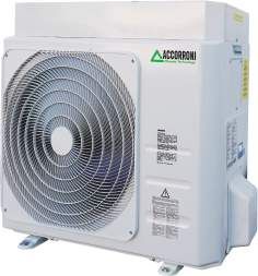
4.2 DIMENSIONS AND TECHNICAL CHARACTERISTICS OF OUTDOOR UNITS
Booster outdoor HR 3.0 - 7.8 Booster outdoor HR 9.0 INVERTER
L P L P
H
H
II I
II I
Models outdoor unit L H P I II Weight
mm mm mm mm mm kg Models outdoor unit L H P I II Weight
Booster HR 3.0 700 552 256 275 435 33 mm mm mm mm mm kg
Booster HR 7.8 902 650 307 350 620 55 Booster HR 9.0 inverter 925 785 380 358 540 62
94.3 INDOOR UNIT HUB RADIATOR PLUS / PLUS SOLAR 8 Water mains inlet (M 1/2 ”)
Main components 9 Booster gas line HR refrigeration circuit 1
1 High temperature system return (M 1”) (5/8” Booster 7.8 / 9.0 - 3/8” Booster 3.0)
2 Low temperature system delivery (M 1”) 10 Liquid line Booster HR refrigerant circuit 1
3 Domestic hot water delivery (M 1/2”) (1/4” Booster 3.0 / 7.8 - 3/8” Booster 9.0)
4 Refrigerant circuit HR Booster gas line 2 11 Solar thermal collector delivery with forced circulation (M 3/4”)
(5/8” Booster 7.8 / 9.0 - 3/8” Booster 3.0) 12 Solar thermal collector return with forced circulation (M 3/4”)
5 Refrigerant circuit HR Booster liquid line 2 13 System technical water pressure gauge
(1/4” Booster 3.0 / 7.8 - 3/8” Booster 9.0) 14 System filling cock
6 High temperature system delivery (M 1 “) 15 Automatic jolly valve for system air vent
7 Low temperature system return (M 1”) 16 Additional heat generator water delivery
17 Additional heat generator water return
18 8 liter system expansion vessel
14 7 2 1 19 8 liter solar expansion vessel (optional)
12 13 6
11 20 Integrative electric heater 2 kW
21 Zone 1 system circulator
22 Zone 2 system circulator (optional)
23 Mix valve for radiant system (optional)
28 29 24 System safety valve 3 bar
30 25 UNIT 2 PLUS solar station (optional)
26 CONTROL MULTI 06 S solar control unit (optional)
31
27 System drain cock
32 28 Digital Booster 1 control unit
33 29 Booster 2 digital control unit
30 Integrative electric heater ON-OFF switch
31 EMERGENCY / INTEGRATION diverter integrative electrical
18 resistance
26 32 System circulator/s ON-OFF switch
33 Solar control unit ON-OFF switch (optional)
21
22
23
28 29
25 24 30
31
32
33
26
19
18
20
27
9 8 4 3
10 5
11
12 7 2 16 1
17 6
15
104.4 PERFORMANCE CHARACTERISTICS OF THE OUTDOOR UNIT BOOSTER HR 3.0
BOOSTER HR 3.0 - THERMAL POWER DELIVERED
Thermal power delivered kW
Heating water delivery temperature °C
Ta (°C) 30 35 40 45 50 55
- 10 1,96 1,93 1,88 1,80 1,67 1,51
-9 2,.02 1,99 1,94 1,86 1,74 1,58
-8 2,08 2,05 2,01 1,93 1,81 1,66
-7 2,14 2,11 2,07 1,99 1,88 1,74
-6 2,20 2,18 2,13 2,06 1,96 1,81
-5 2,27 2,24 2,20 2,13 2,03 1,89
-4 2,33 2,31 2,26 2,19 2,10 1,96
-3 2,40 2,37 2,33 2,26 2,17 2,04
-2 2,47 2,44 2,39 2,33 2,24 2,11
-1 2,54 2,51 2,46 2,40 2,31 2,18
0 2,61 2,58 2,53 2,47 2,38 2,26
1 2,69 2,65 2,60 2,54 2,45 2,33
2 2,76 2,71 2,67 2,61 2,52 2,40
3 2,84 2,80 2,74 2,68 2,59 2,47
4 2,92 2,87 2,82 2,75 2,66 2,55
5 3,01 2,95 2,89 2,82 2,73 2,62
6 3,09 3,03 2,97 2,90 2,81 2,69
7 3,18 3,11 3,05 2,97 2,88 2,77
8 3,27 3,20 3,12 3,05 2,95 2,84
9 3,36 3,28 3,20 3,12 3,03 2,91
10 3,45 3,37 3,29 3,20 3,10 2,98
11 3,55 3,46 3,37 3,28 3,18 3,06
12 3,64 3,59 3,45 3,36 3,25 3,13
13 3,75 3,64 3,54 3,44 3,33 3,20
14 3,85 3,74 3,63 3,52 3,41 3,28
15 3,95 3,83 3,72 3,60 3,48 3,35
BOOSTER HR 3.0 BOOSTER HR 3.0
ABSORBED ELECTRICAL POWER kW C.O.P. THERMAL POWER / ABSORBED POWER
Heating water delivery temperature °C Heating water delivery temperature °C
Ta (°C) 30 35 40 45 50 55 Ta (°C) 30 35 40 45 50 55
- 10 0,66 0,75 0,84 0,94 1,05 1,19 - 10 2,96 2,59 2,25 1,91 1,59 1,27
-9 0,66 0,75 0,84 0,94 1,06 1,19 -9 3,04 2,67 2,32 1,98 1,65 1,33
-8 0,66 0,75 0,84 0,94 1,06 1,19 -8 3,14 2,75 2,39 2,05 1,71 1,39
-7 0,66 0,75 0,84 0,94 1,06 1,19 -7 3,23 2,81 2,47 2,11 1,78 1,46
-6 0,66 0,75 0,84 0,94 1,06 1,19 -6 3,32 2,92 2,54 2,19 1,84 1,52
-5 0,66 0,75 0,84 0,94 1,06 1,19 -5 3,42 3,01 2,62 2,26 1,91 1,58
-4 0,66 0,74 0,84 0,94 1,06 1,20 -4 3,52 3,10 2,70 2,33 1,97 1,64
-3 0,66 0,74 0,84 0,94 1,06 1,20 -3 3,63 3,19 2,78 2,40 2,04 1,70
-2 0,66 0,74 0,84 0,94 1,06 1,20 -2 3,74 3,28 2,86 2,47 2,10 1,76
-1 0,66 0,74 0,84 0,94 1,06 1,20 -1 3,85 3,37 2,94 2,54 2,17 1,82
0 0,66 0,74 0,84 0,94 1,06 1,20 0 3,96 3,48 3,02 2,67 2,23 1,88
1 0,66 0,74 0,84 0,94 1,06 1,20 1 4,08 3,57 3,11 2,69 2,30 1,94
2 0,66 0,74 0,84 0,94 1,06 1,20 2 4,20 3,67 3,20 2,76 2,37 2,00
3 0,66 0,74 0,84 0,94 1,06 1,20 3 4,33 3,78 3,29 2,84 2,43 2,06
4 0,66 0,74 0,83 0,94 1,06 1,20 4 4,46 3,88 3,38 2,92 2,50 2,12
5 0,65 0,74 0,83 0,94 1,06 1,20 5 4,59 4,00 3,47 3,00 2,57 2,18
6 0,65 0,74 0,83 0,94 1,06 1,20 6 4,73 4,11 3,57 3,08 2,64 2,24
7 0,65 0,74 0,83 0,94 1,06 1,20 7 4,87 4,20 3,66 3,16 2,71 2,30
8 0,65 0,74 0,83 0,94 1,06 1,20 8 5,01 4,35 3,76 3,24 2,78 2,36
9 0,65 0,73 0,83 0,94 1,06 1,20 9 5,16 4,47 3,86 3,33 2,85 2,42
10 0,65 0,73 0,83 0,94 1,06 1,20 10 5,32 4,60 3,97 3,42 2,92 2,48
11 0,65 0,73 0,83 0,94 1,06 1,20 11 5,48 4,73 4,08 3,51 3,00 2,54
12 0,65 0,73 0,82 0,93 1,06 1,20 12 5,64 4,86 4,19 3,60 3,07 2,61
13 0,64 0,73 0,82 0,93 1,06 1,20 13 5,81 5,00 4,30 3,69 3,15 2,67
14 0,64 0,73 0,82 0,93 1,06 1,20 14 5,99 5,15 4,42 3,78 3,23 2,74
15 0,64 0,72 0,82 0,93 1,05 1,20 15 6,17 5,29 4,54 3,88 3,31 2,80
114.5 PERFORMANCE CHARACTERISTICS OF THE OUTDOOR UNIT BOOSTER HR 7.8
BOOSTER HR 7.8 - THERMAL POWER DELIVERED
Thermal power delivered kW
Heating water delivery temperature °C
Ta (°C) 30 35 40 45 50 55
- 10 5,12 5,05 4,91 4,69 4,36 3,93
-9 5,27 5,20 5,07 4,86 4,55 4,13
-8 5,43 5,36 5,23 5,03 4,73 4,33
-7 5,58 5,52 5,40 5,20 4,92 4,53
-6 5,75 5,68 5,56 5,37 5,10 4,73
-5 5,91 5,85 5,73 5,55 5,28 4,92
-4 6,09 6,02 5,90 5,72 5,47 5,12
-3 6,26 6,19 6,07 5,90 5,65 5,31
-2 6,44 6,36 6,25 6,08 5,83 5,50
-1 6,63 6,54 6,43 6,26 6,02 5,70
0 6,82 6,73 6,61 6,44 6,20 5,89
1 7,01 6,91 6,79 6,62 6,39 6,08
2 7,21 7,10 6,97 6,80 6,57 6,27
3 7,42 7,30 7,16 6,99 6,76 6,46
4 7,63 7,50 7,35 7,17 6,94 6,65
5 7,84 7,70 7,55 7,36 7,13 6,84
6 8,06 7,91 7,75 7,56 7,32 7,03
7 8,29 8,12 7,95 7,75 7,51 7,22
8 8,52 8,34 8,15 7,95 7,70 7,41
9 8,76 8,56 8,36 8,15 7,90 7,60
10 9,00 8,79 8,57 8,35 8,09 7,79
11 9,25 9,02 8,79 8,55 8,29 7,98
12 9,51 8,86 9,01 8,76 8,49 8,17
13 9,77 9,50 9,24 8,97 8,69 8,36
14 10,04 9,75 9,47 9,19 8,89 8,56
15 10,32 10,00 9,70 9,40 9,09 8,75
BOOSTER HR 7.8 BOOSTER HR 7.8
ABSORBED ELECTRICAL POWER kW C.O.P. THERMAL POWER / ABSORBED POWER
Heating water delivery temperature °C Heating water delivery temperature °C
Ta (°C) 30 35 40 45 50 55 Ta (°C) 30 35 40 45 50 55
- 10 1,78 2,00 2,25 2,52 2,83 3,19 - 10 2,87 2,52 2,18 1,91 1,54 1,23
-9 1,78 2,00 2,25 2,53 2,84 3,19 -9 2,96 2,60 2,25 1,98 1,60 1,29
-8 1,78 2,00 2,25 2,53 2,84 3,20 -8 3,05 2,68 2,33 2,05 1,67 1,35
-7 1,78 2,00 2,25 2,53 2,84 3,20 -7 3,14 2,76 2,40 2,05 1,73 1,41
-6 1,78 2,00 2,25 2,53 2,85 3,21 -6 3,23 2,84 2,47 2,19 1,79 1,47
-5 1,78 2,00 2,25 2,53 2,85 3,21 -5 3,32 2,92 2,55 2,26 1,85 1,53
-4 1,78 2,00 2,25 2,53 2,85 3,22 -4 3,42 3,01 2,62 2,33 1,92 1,59
-3 1,78 2,00 2,25 2,53 2,86 3,22 -3 3,53 3,09 2,70 2,40 1,98 1,65
-2 1,77 2,00 2,25 2,54 2,86 3,23 -2 3,63 3,18 2,78 2,47 2,04 1,71
-1 1,77 2,00 2,25 2,54 2,86 3,23 -1 3,74 3,28 2,86 2,54 2,11 1,77
0 1,77 2,00 2,25 2,54 2,86 3,23 0 3,85 3,37 2,94 2,53 2,17 1,82
1 1,77 1,99 2,25 2,53 2,86 3,23 1 3,96 3,47 3,02 2,69 2,23 1,88
2 1,77 1,99 2,25 2,53 2,86 3,23 2 4,08 3,62 3,10 2,68 2,30 1,94
3 1,76 1,99 2,24 2,53 2,86 3,23 3 4,20 3,67 3,19 2,84 2,36 2,00
4 1,76 1,99 2,24 2,53 2,86 3,23 4 4,33 3,77 3,28 2,92 2,43 2,06
5 1,76 1,98 2,24 2,53 2,86 3,23 5 4,46 3,88 3,37 3,00 2,49 2,11
6 1,76 1,98 2,24 2,53 2,86 3,23 6 5,59 3,99 3,46 3,08 2,56 2,17
7 1,75 1,98 2,23 2,52 2,86 3,23 7 4,73 4,14 3,56 3,07 2,63 2,23
8 1,75 1,98 2,23 2,52 2,85 3,23 8 4,87 4,22 3,65 3,24 2,70 2,29
9 1,75 1,97 2,23 2,52 2,85 3,23 9 5,02 4,34 3,75 3,33 2,77 2,35
10 1,74 1,97 2,22 2,52 2,85 3,23 10 5,17 4,47 3,86 3,42 2,84 2,41
11 1,74 1,96 2,22 2,51 2,85 3,23 11 5,32 4,59 3,96 3,51 2,91 2,47
12 1,73 1,95 2,22 2,51 2,84 3,22 12 5,48 4,47 4,07 3,49 2,98 2,53
13 1,73 1,95 2,21 2,50 2,84 3,22 13 5,65 4,86 4,18 3,69 3,06 2,60
14 1,73 1,95 2,21 2,50 2,83 3,22 14 5,82 5,00 4,29 3,78 3,14 2,66
15 1,72 1,95 2,20 2,49 2,83 3,21 15 5,99 5,14 4,41 3,88 3,21 2,72
124.6 PERFORMANCE CHARACTERISTICS OF THE OUTDOOR UNIT BOOSTER HR 9.0 INVERTER
BOOSTER HR 9.0 INV. - THERMAL POWER DELIVERED
Thermal power delivered kW
Heating water delivery temperature °C
Ta (°C) 30 35 40 45 50 55
- 10 5,84 5,81 5,79 5,71 5,47 4,98
-7 6,23 6,19 6,17 6,08 5,82 5,31
-2 6,84 6,81 6,78 6,67 6,39 5,84
2 7,34 7,31 7,28 7,15 6,85 6,28
7 8,03 8,01 8,02 7,92 7,54 6,89
12 8,84 8,82 8,78 8,62 8,27 7,63
BOOSTER HR 9.0 INVERTER BOOSTER HR 9.0 INVERTER
ABSORBED ELECTRICAL POWER kW C.O.P. THERMAL POWER / ABSORBED POWER
Heating water delivery temperature °C Heating water delivery temperature °C
Ta (°C) 30 35 40 45 50 55 Ta (°C) 30 35 40 45 50 55
- 10 2,02 2,25 2,51 2,80 3,12 3,47 - 10 2,89 2,58 2,31 2,04 1,75 1,44
-7 1,98 2,21 2,47 2,27 3,09 3,43 -7 3,15 2,81 2,50 2,20 1,89 1,55
-2 1,88 2,12 2,39 2,68 3,00 3,34 -2 3,64 3,22 2,84 2,49 2,13 1,75
2 1,78 2,02 2,29 2,59 2,91 3,24 2 4,12 3,62 3,18 2,76 2,36 1,94
7 1,63 1,89 2,13 2,39 2,73 3,09 7 4,91 4,24 3,76 3,31 2,76 2,23
12 1,40 1,64 1,90 2,19 2,50 2,82 12 6,30 5,38 4,61 3,93 3,31 2,71
134.7 TECHNICAL DATA TABLE BOOSTER HUB RADIATOR PLUS / PLUS SOLAR
DESCRIPTION U.M. HR 3.0 HR 7.8 HR 9.0 INVERTER
Thermal power (1) kW 3,11 8,12 3,54 / 8,01 / 8,81*
Absorbed power (1) kW 0,74 1,96 1,89
C.O.P. (1) W/W 4,20 4,14 4,24
Thermal power (2) kW 2,97 7,75 2,85 / 7,92 / 8,71*
Absorbed power (2) kW 0,94 2,52 2,39
C.O.P. (2) W/W 3,16 3,07 3,31
Thermal power (3) kW 2,58 6,73 2,54 / 7,04 / 7,74*
Absorbed power (3) kW 0,74 2,00 2,00
C.O.P. (3) W/W 3,48 3,37 3,52
Thermal power (4) kW 2,47 6,44 2,46 / 6,82 / 7,50*
Absorbed power (4) kW 0,94 2,54 2,74
C.O.P. (4) W/W 2,67 2,53 2,68
Thermal power (5) kW 2,11 5,52 2,31 / 6,41 / 7,05*
Absorbed power (5) kW 0,75 2,00 2,54
C.O.P. (5) W/W 2,81 2,76 3,04
Thermal power (6) kW 1,99 5,20 2,25 / 6,25 / 6,88*
Absorbed power (6) kW 0,94 2,53 2,68
C.O.P. (6) W/W 2,11 2,05 2,39
SCOP (7) W/W 3,78 3,71 3,94
Seasonal heating efficiency (ηs) % 153,10 150,30 159,62
Energy efficiency class (8) A++ / A A++ / A+++
Type of compressor Rotation ON-OFF Twin Rotary DC INV.
Compressors n. 1
Refrigerant circuits n. 1
Defrost method Reverse cycle with immersion condenser
Type of refrigerant R410A
Temperature technical water min/max °C +30 / +58
Amount of refrigerant (pre-inserted) kg 1,1 2,0 2,2
Min distance between outdoor and indoor unit m 3
Max dist. betw. outdoor/indoor unit without recharging m 5
Max distance between outdoor/indoor unit with recharge m 15
Max diff. in height between outdoor/indoor unit m 5
Refrigerant gas line connection R410A 3/8” 5/8” 5/8”
Coolant line connection R410A 1/4” 1/4” 3/8”
Sound power (9) dB(A) 65,1 68,4 64,0
Sound pressure 1 m (10) dB(A) 51,2 54,7 32,8
External temperature operating limits °C -15 / +45 -20 / +46
Power supply 230V/1/50Hz
Max absorbed power kW 0,94 2,53 4,70
Max absorbed A 4,30 11,57 20,40
Weight Kg 33 55 62
(1) Heating: outside air temperature (6) Heating: outside air temperature
7 °C b.d. - 6 °C b.w.; inlet / outlet water temperature30/35 °C -7 °C b.d.; inlet / outlet water temperature 40/45 °C
(2) Heating: outside air temperature (7) Heating: condizioni climatiche medie; temperatura acqua ingresso/uscita 30/35 °C
7 °C b.d. - 6 °C b.w.; inlet / outlet water temperature 40/45 °C (8) Water 35 °C / 55°C
(3) Heating: outside air temperature (9) Measurements made according to UNI EN 14511
0 °C b.d.; water temperature inlet/outlet 30/35 °C in heating mode and boundary conditions (1)
(4) Heating: outside air temperature (10) Value calculated according to ISO 3744: 2010
0 °C b.d.; water temperature inlet/outlet 40/45 °C (*) By activating the maximum HZ function
(5) Heating: outside air temperature
-7 °C b.d.; water temperature inlet/outlet 30/35 °C
4.8 DHW WITHDRAWAL TABLE HUB RADIATOR PLUS / PLUS SOLAR 250
DESCRIPTION U.M. HR 3.0 HR 7.8 HR 9.0 inverter
DHW withdrawal at 40 °C - storage at 55 °C - inlet water at 10 °C l 202 212 212
DHW withdrawal at 40 °C - storage at 55 °C - inlet water at 15 °C l 218 242 242
HP recovery time from 38 °C to 55 °C - Outdoor temp. 7 °C * min 82 36 30
HP recovery time+resistance from 38 °C to 58 °C - External temp. 7 °C* min 54 24 20
Water withdrawal at 40 °C with storage at 62 °C with inlet water at 10 °C l 228 254 254
Water withdrawal at 40 °C with storage at 62 °C with inlet water at 15 °C l 262 290 290
HP recovery time+resistance from 38 ° C to 62 °C - External temp. 7 °C* min 98 44 36
Recovery time from 10 °C to 55 °C - Outdoor temp. 7 °C* min 226 88 84
*Data calculated with the heating system off
144.9 DHW WITHDRAWAL TABLE HUB RADIATOR PLUS / PLUS SOLAR 400
DESCRIPTION U.M. HR 3.0 HR 7.8 HR 9.0 inverter
DHW withdrawal at 40 °C - storage at 55 °C - inlet water at 10 °C l 332 348 348
DHW withdrawal at 40 °C - storage at 55 °C - inlet water at 15 °C l 358 396 398
HP recovery time from 38 °C to 55 °C - Outdoor temp. 7 °C * min 134 58 48
HP recovery time+resistance from 38 °C to 58 °C - External temp. 7 °C* min 88 38 32
Water withdrawal at 40 °C with storage at 62 °C with inlet water at 10 °C l 374 416 418
Water withdrawal at 40 °C with storage at 62 °C with inlet water at 15 °C l 430 474 476
HP recovery time+resistance from 38 ° C to 62 °C - External temp. 7 °C* min 156 70 58
Recovery time from 10 °C to 55 °C - Outdoor temp. 7 °C* min 362 140 134
*Data calculated with the heating system off
4.10 ACCUMULATION UNIT TECHNICAL DATA TABLE HUB RADIATOR PLUS / PLUS SOLAR
DESCRIPTION U.M. 250 250 SOLAR 400 400 SOLAR
Technical storage water content l 252 243 404 395
Max flow rate electronic inverter circulator m3/h 3,3
Max head electronic inverter circulator m 6,2
Electric absorption electronic circulator inverter W 3 - 45
System expansion vessel volume l 8 8
Number of system expansion vessels n. 2 3
Expansion vessel preload bar 1
Safety valve calibration bar 3
Electrical resistance of back up W 2000
Max number of HR 3.0 boosters that can be combined n. 2 4
Max number of HR 7.8 boosters that can be combined n. 2 3
Max numb. HR 8.0 inverter boosters to be combined n. 2 3
Water temperature min / max °C +20 / +55
Cold water inlet and DHW outlet hydraulic connections 1/2”
System delivery and return hydraulic connections 1”
DHW exchanger surface in copper m2 3,15 4,54
Solar flow and return hydraulic connections - 3/4” - 3/4”
Pressure drop in domestic hot water exchanger in copper Pa 1,8 2,6
Solar exchanger surface in copper m2 - 1,6 - 2,0
Pressure drop in copper solar exchanger Pa - 1,2 - 1,7
Type of insulation High density extruded expanded polystyrene
Insulation thickness cm 4,5
Power supply 230V/1/50Hz
Internal unit accumulation heat loss kWh/24h 1,58
Degree of protection IPX5D
Shipping weight kg 184 188 222 226
Operating weight kg 436 440 626 621
4.11 ACCESSORIES HUB RADIATOR PLUS / PLUS SOLAR
REMOTE CONTROL AND COMMAND PANEL ADDITIONAL LOW TEMPERATURE SYSTEM PUMP
KIT WITH CLIMATIC MIXING
LOAD CONTROL RELAY FOR MANAGING THE MIXING VALVE FOR RADIANT SYSTEMS FOR MOD.
ABSORBED POWER WITH FIXED AND MOTORIZED ADJUSTMENT
15You can also read