HYBRID + ACTIVE GANGING SIPM CIRCUIT - VD-PDS DUNE COLLABORATION MEETING - MAY 20TH, 2021 - MAY 20TH, 2021 GUSTAVO ...
←
→
Page content transcription
If your browser does not render page correctly, please read the page content below
Hybrid + Active ganging
     SiPM circuit
               VD-PDS
 DUNE Collaboration Meeting - May 20th, 2021

         Gustavo Cancelo (Fermilab)
           Dante Totani (UCSB)
                      1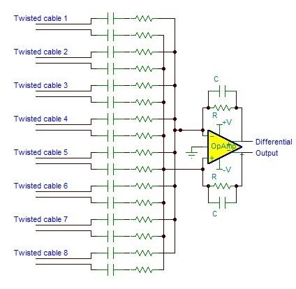
X-ARAPUCA tile
•Each X-ARAPUCA tile is populated
 with 160 SiPMs

•Organized in 8 groups of 20 SiPM.

•The 20 SiPM are passively summed in
 “hybrid" mode.

•The 8 groups then are summed in an
 active summing stage, using an
 OpAmp.

                                       2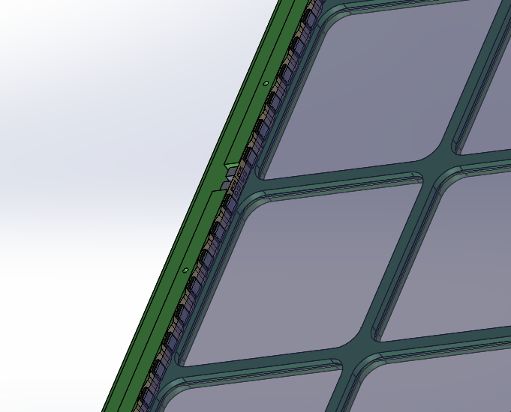
Hybrid circuit                                     2R
                                                            +V

                                                        C      R
The hybrid connection advantages:                   R                 Constant voltage
                                                                        (+V, ground)
•   Same potential on the surface of SiPM’s.            C      R
•   Small capacitance → short recovery time         R
•   Same bias voltage of a single SiPM                  C      R
                                                    R
    DC current SiPM+2R (R = 10 kΩ).                     C      2R
    AC current SiPM + C (C ∼ 15 nF)

                                                   GND      Fast pulse (signal)

                                               3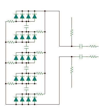
The 160 SiPM’s from each X-ARAPUCA tile are arranged in 8
        subgroups of 20 SiPM passively connected in “hybrid mode”.
                             +V
               2R

                                                                 RC stage before +V /
                    C   R
                             R                                   GND provide the AC
                                                           V2
               R
                                   C’          OutPut 2          output. Signal can be
                                         R’
                    C   R                                        read by both output.

               R                                           V1
                                   C’    R’
                                               OutPut 1          Since the two outputs
                    C   R    R                                   are specular, reading the
               R
                                                                 signal in “di erential”
                                        R′ = 50 Ω                mode allows to increase
                                                          ΔV12
                    C   2R              C′ ∼ 15 nF               the signal-noise ratio.
                             GND
                                        R = 10 kΩ
                                        C ∼ 15 nF
                                               4


          ff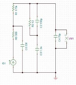
Active ganging
                                                                  Each couple of outputs goes in an OpAmp
                                                                  stage: “active ganging stage”.
                                                  ADC
                                                                  The OpAmp allows to sum multiple channels
                                                                  decoupling the capacitance of each channel.
                                                                  At the same time it can provide a signal
                                                                  amplification (G ~ 10).
                                                                  Increasing/tuning the signal in order to match:
                                                                  •   ADC dynamic range requirement
                                                                  •   SPE noise ratio
                                                                  •   Maximum number of photon collectable

A Full Di erential OpAmp, together to read a better signal (combing the two outputs) is the best to match with the ADC device.

                                                              5
   ff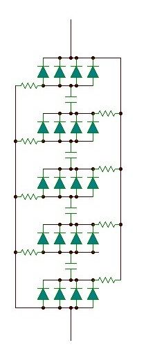
Multiple con iguration
Different configurations are under consideration for the signal transmission over fibers:

Digital transmission

-   1 ADC per X-ARAPUCA tile → 8 channels in a single Full Differential OpAmp.
-   2 ADC per X-ARAPUCA tile → 4 channels in a single Full Differential OpAmp.

Analog transmission

- 1 Analog transmitter → 8 channels in a single OpAmp (not differential mode).

However for all the cases the SiPM Hybrid configuration and the Summing Stage are expected to not
have any significative changes.

                                                    6
                                     f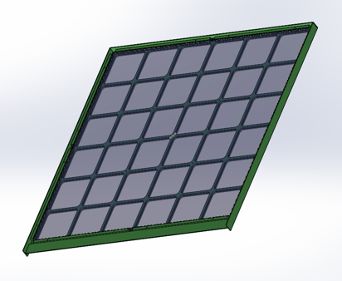
Readout matching
SiPM equivalent electric circuit has been developed by Gustavo Cancelo (FCC) to study the device response.
A solution for unwanted effects (undershot, changes in recovery time, signal distortions) seems to be available.
The RC components, at the readout stage, have to be careful evaluated to match the timing response of the
circuit (dependent by the hybrid configuration as well the SiPM equivalent impedance).
The model developed match with a SPICE simulation.
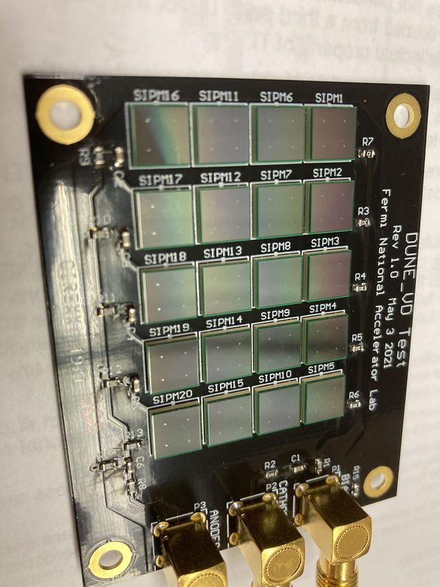
A “version-zero” of an hybrid circuit board (20 SiPM)
has been delivered yesterday.
Tests will be performed to characterize the
hybrid circuit and prove the model validity.
As first stage, we aim to define the
hybrid circuit response in term of: SPE gain,
signal amplitude, signal noise ratio, etc…
7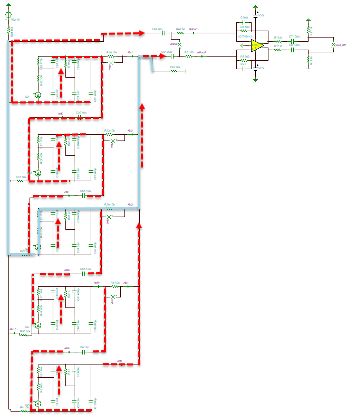
Hybrid model and simulations
          •The dynamics of a firing microcell in a multi microcell SiPM can be
          represented by a passive electric circuit and a current source
          (Seifert, 2009),(Corsi, 2007), (Wangerin,2008).
          •The model parameters can be extracted from the SiPM datasheet
          (e.g. Hamamatsu S13360-5060VE).
          •A typical 6x6mm 50 μm pitch SiPM has the following model.

          •The part inside the rectangular red line represents the firing microcell.
           The part outside are the N-1 passive microcells which act as a load.
          •We started with the study and simulation of a single SiPM and finalize
           with a full 4 x 5 hybrid model.
          •The hybrid model is biased and also loaded by an Op Amp stage with gain
           based on the THS4131 high bandwidth fully differential amplifier.
                        8
5 x 4 hybrid with bias
and preamp
•Each of the 5 stages is a parallel of 4 SiPMs
•The blue line represents a DC bias path.
–For the Vbias the SiPMs are in parallel, so Vbias hybrid is equal to the bias of a single SiPM.
• The red dotted trace represents the serial path of the signal.
–In this example the 2nd SiPM fires and the signal goes through 1st stage.
Hybrid 1st stage and OpAmp zoomed in
9The hybrid transfer function was modeled using the Laplace transform
•The transfer function of the dynamic model is obtained using the Laplace transform in the frequency
domain. Then the time response is obtained using the inverse transform.
•The dynamics is a function of the poles and zeros of the transfer function given by C and R’s in the circuit.
•Simulations agree with analytical derivations.
Signal rise time = 12n
No undershoot
840uV for a single PE and
for ampli er gain of 10
10
fi
.
sYou can also read