I2C_Read_Ext_Device_1 for KIT_AURIX_TC375_LK - Read external device MAC address via I2C - Infineon ...
←
→
Page content transcription
If your browser does not render page correctly, please read the page content below
I2C_Read_Ext_Device_1
for KIT_AURIX_TC375_LK
Read external device MAC address via I2C

AURIX™ TC3xx Microcontroller Training
V1.0.0
                Please read the Important Notice and Warnings at the end of this document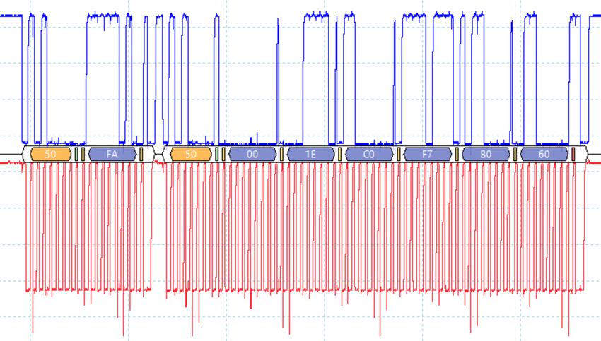
Scope of work

An I2C module configured as I2C master is used to read a register of an
external device.

An I2C module configured as I2C master is used to read the MAC address
stored in Microchip 24AA02E48, a 2 Kb I2C Serial EEPROM with Pre-
Programmed EUI-48™ MAC ID mounted on the board
KIT_A2G_TC375_LITE. The AURIX™ device reads the MAC address
through the I2C module and stores it into a global variable.

                        Copyright © Infineon Technologies AG 2021. All rights reserved.
Introduction
› The I2C protocol was developed to provide a simple and efficient data
transfer between multiple devices over a short distance
› It uses a bidirectional serial bus with two wires. A serial data line (SDA)
and a serial clock line (SCL) are carrying the information between multiple
devices
› Both lines are connected to a positive supply voltage via pull-up resistors
› An I2C device can work as a master or as a slave. The master, which is
normally a microcontroller, initiates and terminates the transfer and
generates the clock pulse
› A specific slave can be addressed by the master via a 7- or 10-bit
address. Afterwards the master starts the communication
– Data can flow in either direction and can be set via a data direction bit,
which is transmitted by the master
Copyright © Infineon Technologies AG 2021. All rights reserved.Hardware setup
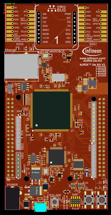
This code example has been developed for the
board KIT_A2G_TC375_LITE.
The Microchip 24AA02E48 (1) is mounted on
the board and connected via the I2C bus to the 1
microcontroller.
The used data lines are connected to the
positive power supply via two pull-up resistors.
The Microchip 24AA02E48 is a 2 Kb I2C Serial
EEPROM with Pre-Programmed EUI-48™
MAC ID.
Copyright © Infineon Technologies AG 2021. All rights reserved.Implementation
Configuring the I2C communication
The configuration of the I2C communication is done once in the setup phase
in two different steps:
› The initialization of the I2C module by initializing an instance of the
IfxI2c_I2c_Config structure
› The initialization of every device that is connected to the I2C module (in this
case, the Microchip 24AA02E48) by initializing an instance of the
IfxI2c_I2c_deviceConfig structure for each device
Copyright © Infineon Technologies AG 2021. All rights reserved.Implementation
Configuring the I2C module
The function IfxI2c_I2c_initConfig() initializes an instance of the structure
IfxI2c_I2c_Config with its default values.
The IfxI2c_I2c_Config structure allows setting the parameters to initialize the
module:
› baudrate – to set the clock speed in bit/s. Typical values are 100 kbit/s in
standard mode, 400 kbit/s in fast mode and 3.4 Mbit/s in high-speed mode
› pins – a structure to set the port pins used for the communication
A serial data line (SDA) and a serial clock line (SCL) carry the information
between the devices, therefore two port pins are required
The function IfxI2c_I2c_initModule() initializes and activates the I2C module
with the user configuration in master mode.
The functions above are provided by the iLLD header IfxI2c_I2c.h.
Copyright © Infineon Technologies AG 2021. All rights reserved.Implementation
Configuring the I2C device
The function IfxI2c_I2c_initDeviceConfig() initializes an instance of the
structure IfxI2c_I2c_deviceConfig with its default values.
Afterwards, the 7-bit slave address can be set through the parameter
deviceAddress.
The function IfxI2c_I2c_initDevice() finalizes the I2C initialization by connecting
the device configuration with the preconfigured I2C module.
The functions above are provided by the iLLD header IfxI2c_I2c.h.
Copyright © Infineon Technologies AG 2021. All rights reserved.Implementation
Establish I2C communication
Data transfer between the external device and the microcontroller is
divided into two steps:
› Firstly, the microcontroller is transmitting the address of the register, in which
the requested data is stored on the external device (the register containing
the MAC address of Microchip 24AA02E48 is 0xFA). This is done using the
IfxI2c_I2c_write() function
› Then, the reading of the MAC address is started with the function
IfxI2c_I2c_read()
Both the write and read functions are defined in the iLLD header IfxI2c_I2c.h.
Copyright © Infineon Technologies AG 2021. All rights reserved.Run and Test
After code compilation and flashing the device, perform the following steps:
› Start a debug session and watch the global array g_macAddr
› Resume the debug session and suspend it after a few seconds
› Watch the hexadecimal value of the global array g_macAddr
Note: The MAC address is unique for each board.
Copyright © Infineon Technologies AG 2021. All rights reserved.Run and Test
› A second test can be performed with
an oscilloscope. Two oscilloscope
probes can be connected to SDA and
SCL pins to observe the generated
and received signals
Copyright © Infineon Technologies AG 2021. All rights reserved.Run and Test
The following waveforms should be seen on the oscilloscope after pressing
the PORST push button:
› First data section: device address byte and register address
› Second data section: device address byte and six bytes of data
(Please refer to the next slide for more details about the data sections)
SDA
SCL
Copyright © Infineon Technologies AG 2021. All rights reserved.Run and Test
› First data section: To perform a read operation, the master addresses the
slave (transmitting the device address (0x50) with the Read/Write bit set
to „write“) and sends the requested register to read (transmitting 0xFA
afterwards)
› Second data section : The reading process is started by transmitting the
device address (0x50) and setting Read/Write bit to „read“; six bytes from
the Microchip 24AA02E48 device, containing the MAC address, are then
received
Copyright © Infineon Technologies AG 2021. All rights reserved.References
› AURIX™ Development Studio is available online:
› https://www.infineon.com/aurixdevelopmentstudio
› Use the „Import...“ function to get access to more code examples.
› More code examples can be found on the GIT repository:
› https://github.com/Infineon/AURIX_code_examples
› For additional trainings, visit our webpage:
› https://www.infineon.com/aurix-expert-training
› For questions and support, use the AURIX™ Forum:
› https://www.infineonforums.com/forums/13-Aurix-Forum
Copyright © Infineon Technologies AG 2021. All rights reserved.Trademarks
All referenced product or service names and trademarks are the property of their respective owners.
Edition 2021-03 IMPORTANT NOTICE For further information on the product,
Published by The information given in this document shall in no technology, delivery terms and conditions and
Infineon Technologies AG event be regarded as a guarantee of conditions or prices please contact your nearest Infineon
81726 Munich, Germany characteristics (“Beschaffenheitsgarantie”) . Technologies office (www.infineon.com).
With respect to any examples, hints or any typical
© 2021 Infineon Technologies AG. WARNINGS
values stated herein and/or any information
All Rights Reserved. Due to technical requirements products may
regarding the application of the product, Infineon
contain dangerous substances. For information
Technologies hereby disclaims any and all
Do you have a question about this on the types in question please contact your
warranties and liabilities of any kind, including
document? nearest Infineon Technologies office.
without limitation warranties of non-infringement
Email: erratum@infineon.com
of intellectual property rights of any third party. Except as otherwise explicitly approved by
Infineon Technologies in a written document
Document reference In addition, any information given in this
signed by authorized representatives of Infineon
I2C_Read_Ext_Device_1_KIT_TC375_LK document is subject to customer’s compliance
Technologies, Infineon Technologies’ products
with its obligations stated in this document and
may not be used in any applications where a
any applicable legal requirements, norms and
failure of the product or any consequences of the
standards concerning customer’s products and
use thereof can reasonably be expected to result
any use of the product of Infineon Technologies in
in personal injury.
customer’s applications.
The data contained in this document is exclusively
intended for technically trained staff. It is the
responsibility of customer’s technical
departments to evaluate the suitability of the
product for the intended application and the
completeness of the product information given in
this document with respect to such application.You can also read